EP0290243A2 - Système de transducteurs à alimentation optique - Google Patents
Système de transducteurs à alimentation optique Download PDFInfo
- Publication number
- EP0290243A2 EP0290243A2 EP88304039A EP88304039A EP0290243A2 EP 0290243 A2 EP0290243 A2 EP 0290243A2 EP 88304039 A EP88304039 A EP 88304039A EP 88304039 A EP88304039 A EP 88304039A EP 0290243 A2 EP0290243 A2 EP 0290243A2
- Authority
- EP
- European Patent Office
- Prior art keywords
- sensor
- optical
- pulses
- pulse
- time
- Prior art date
- Legal status (The legal status is an assumption and is not a legal conclusion. Google has not performed a legal analysis and makes no representation as to the accuracy of the status listed.)
- Withdrawn
Links
Images


Classifications
-
- H—ELECTRICITY
- H04—ELECTRIC COMMUNICATION TECHNIQUE
- H04B—TRANSMISSION
- H04B10/00—Transmission systems employing electromagnetic waves other than radio-waves, e.g. infrared, visible or ultraviolet light, or employing corpuscular radiation, e.g. quantum communication
- H04B10/80—Optical aspects relating to the use of optical transmission for specific applications, not provided for in groups H04B10/03 - H04B10/70, e.g. optical power feeding or optical transmission through water
- H04B10/806—Arrangements for feeding power
- H04B10/807—Optical power feeding, i.e. transmitting power using an optical signal
Definitions
- the present invention relates to devices and systems for sensing physical parameters, and, more particularly, to optically powered sensors and sensing systems in which optical energy from a source is provided to one or more sensors which, in turn, provide information-bearing optical energy representative of the sensed parameter.
- Various types of sensors and sensor systems are known for measuring physical parameters.
- electrical sensors which provide a variation in resistance, capacitance, or other electrical characteristics as a function of a sensed physical parameter have been used to provide an electrical current or voltage output.
- the resistance of a thermistor varies as a function of its temperature and can be used in a simple bridge circuit to provide a temperature responsive output current.
- capacitors and capacitor-like structures can be used to provide electrical signal outputs that are responsive to environmental parameters that affect the dielectric constant of the capacitor.
- groups of sensors are typically interconnected with a controller which provides source electrical power to the various sensors and measures or otherwise senses the parameter-affected electrical characteristic.
- electrical sensors and electrical interconnections represent highly developed and reliable technology, although unshielded systems can be subject to electromagnetic interference (EMI).
- EMI electromagnetic interference
- Optical fiber transmission is best suited to digitally encoded optical pulses in which the information to be conveyed is encoded by varying an attribute of the pulse, such as the pulse width, amplitude, or repetition rate.
- Efforts directed to the transmission of analog light through optical fibers is less than optimal because of the substantial variation in attenuation for the transmitted energy as a consequence of the fiber temperature, external pressure applied to the fiber, the presence of small-radius bends in the fiber, and the cumulative effects of defects in the fiber.
- optical energy is transmitted via optical fibers to a sensor which includes a photodetector and a storage capacitor for converting the input optical energy to electricity for storage in the capacitor.
- a transducer such as a temperature sensor, uses the stored electrical energy to provide an electrical output to a pulse width modulator, such as a light emitting diode or a laser diode, to transmit one or more return pulses indicative of the measured parameter. While this system operates to provide duration-modulated pulses, the overall accuracy of the measurement is a function of the stored energy and the accuracy can degrade with changing characteristics of the storage capacitor, as can occur, for example, with changes in temperature and component ageing.
- the use of pulse width modulation requires that the light emitted diode or laser diode be powered during the transmission of the entire pulse.
- the optical energy emitter can consume the major portion of the available stored energy and represent a constraint to efficient operation.
- an optically powered sensor system of the kind comprising a sensor having a store for receiving optical energy and providing a source of stored electrical energy from the optical energy, a transducer for sensing a variable parameter and providing an electrical characteristic that varies as a function of the sensed parameter and means for providing an optical signal that varies as a function of the sensed parameter characterised in that the optical signal providing means uses energy provided by the store, and provides an optical signal in the form of a pulse signal having at least one attribute that varies as a function of the sensed parameter and at least another attribute that is determined by a predetermined reference value.
- FIG. 1 An optically powered sensor system is shown in schematic form in FIG. 1 and is designated generally therein by the reference character 10.
- a plurality of sensors S0, S1, ... S n-1 , S n are connected by respective optical fibers f0, f1, ... f n-1 , f n to a distribution coupler 12, which, in turn, is connected to another coupler 14 through an optical fiber bus 16.
- the coupler 14 is designed to distribute optical energy from the bus 16 to the respective sensors S n and, conversely, direct optical energy from the sensors S n along the bus 16 to the coupler 14.
- the couplers 12 and 14 can take the form of star-type couplers or lateral couplings.
- a system controller 22 is connected to the optical source 18 and the optical receiver 20 and functions, as described below, to drive the optical source 18 to introduce optical energy into the system and to process the return signals from the optical receiver 20.
- the controller 22 includes a logic unit 24 that operates through a recurring cycle under the control of a clock 26 to provide current through a drive amplifier 28 to cause the optical source 18 to direct optical energy through the coupler 14 and the bus 16 to the coupler 12 and the various sensors S n . Additionally, an amplifier 30 accepts pulse signals from the optical receiver 20 for presentation to the logic unit 24.
- the controller 22 operates under the general control of a micro-processor 32 with communication provided through a bus 34 and respective I/O ports (unnumbered).
- An output device 36 such as a multi-digit display, is connected to the micro-processor 32 and provides output information as to the parameters sensed by the sensors S n .
- each sensor S n includes a transducer 40 that has a characteristic, such as resistance, which changes in a predictable manner with the sensed parameter.
- a pulse encoder 42 is connected to the transducer 40 and to a fixed-value reference 44 and provides a pulse output, as described more fully below, to an output driver 46 which, in turn, drives a laser diode 48 to provide optical pulses through the coupler 12 and the bus 16.
- the transducer 40 can take the from of a thermistor that changes resistance with temperature, and the reference 44 can take the form a precision, fixed-value resistor.
- Optical energy provided by the optical energy source 18 through the bus 16 and the coupler 12 is provided to a power converter 50 within each sensor S n which includes a series-connected array of photodiodes 52 in shunt circuit with a storage capacitor 54 and in series circuit with a diode 56.
- Optical energy provided through the bus 16 and the coupler 12 is converted to a DC potential by the photodiodes 52 and stored in the shunt-connected capacitor 54.
- the diode 56 has a low forward voltage drop and serves to isolate the photodiodes 52 and the capacitor 54 from the remainder of the circuitry.
- a power switch 58 is connected to the power converter 50 and selectively provides power to the pulse encoder 42 under the control of a timing circuit 60.
- the power switch 58 can take the form of a MOSFET or a gate-triggered thyristor.
- the pulse encoder 42 functions to provide a series of pulse signals, as explained below in relationship to FIG. 4, that provide information related to the measured parameter and the reference value provided by the reference 44.
- the pulse encoder 42 includes a one-shot pulse generator 62 that controls a flip-flop 66 which switches between set and reset states with successive pulses provided by the pulse generator.
- the one-shot pulse generator 62 is of the type that provides an output pulse of varying duration in response to an input value, such as an input resistance.
- a switch 64 is connected to the input of the one-shot pulse generator 62 and is controlled by the timing circuit 60 to connect either the reference 44 to the input of the one-shot pulse generator 62 or the series-connected value of the reference 44 and the transducer 40.
- the switch 64 can take the form, for example, of an FET that is selectively gated to shunt the transducer 40.
- the duration of the pulse output of the one-shot pulse generator 62 is controlled by the switch 64 to be of a first duration controlled by the reference 44 only or a second value controlled by the sum of the values provided by the reference 44 and the transducer 40, which latter value is a function of the measured parameter.
- the successive pulses of varying duration from the one-shot pulse generator 62 cause the flip-flop 66 to alternate between its binary HI or LO states with each transition.
- Another one-shot pulse generator 68 is connected to the flip-flop 66 and is triggered on each transition between the set and reset states to produce a fixed, short duration pulse with each state change.
- the optically powered sensor system operates in accordance with the flow diagram of FIG. 5 to sense the measured parameter and provide a pulse sequence, as shown in FIG. 4C, containing information representative of the measured parameter as well as the reference value.
- the system is initialized by transmitting optical energy from the optical energy source 18 through the bus 16 for distribution to all sensors S n in the system.
- the photodiodes 52 of each sensor S n convert the distributed optical energy to an electrical current and charge the capacitor 54 of each sensor S n to a full charge or near full charge condition.
- the optical energy provided from the optical source 18 is of a sufficient duration and intensity to assure a sufficient charge in the capacitor 54 of each sensor S n .
- the distributed optical energy is halted at time T0 by the controller 22 in response to commands provided from the micro-processor 32.
- the termination of the distributed optical energy is detected by each sensor S n and the power switches 58 of each of the sensors S n are switched to apply power to the remaining sensor circuitry.
- a current path is provided through the reference 44 of each sensor S n with the resulting current fixed by the value of the reference 44, and a current path is provided through the respective transducer 40 with the current flow through the transducer 40 responsive to the sensed parameter.
- the transducer 40 is a thermistor
- current flow provided through the power switch 58 will be determined by the thermistor temperature.
- the pulse encoder 42 of each sensor S n is provided with a sensor specific time delay between time T1 and time T2; in the preferred embodiment, the time delay is 450 microseconds.
- the time T1 to T2 is 450 microseconds for a first sensor, 900 microseconds for a second sensor, 1350 microseconds for a third sensor, etc.
- This sensor-specific time delay prior to the transmission of return pulses from the sensor to the system controller to allow a predetermined 'time window' for each of the sensors S n to effect transmission to the system controller 22.
- the various sensors S n of the system thus transmit return pulses in a predetermined time-multiplexed sequence.
- the pulse encoder 42 is controlled by the timing circuit 60 of the sensor S n to provide a series of short-duration pulses containing information regarding the value of the sensed parameter.
- the output of the pulse encoder 42 is normally binary HI at time T2 and switches to binary LO at time T3 and then returns to binary HI at time T4.
- the transitions at time T3 and time T4 cause successive state changes in the flip-flop 66 and trigger the one-shot pulse generator 68 to provide two successive short-duration pulses P1 and P2 (FIG. 4D) occurring at and spaced by the time difference between time T3 and T4.
- the pulse spacing between times T3 and T4 is determined by the value of the reference 44 and is relatively fixed for all the sensors S n .
- the pulse output remains at binary HI until time T5 when the output switches to binary LO and then returns to binary HI at time T6.
- the transitions at time T5 and time T6 cause successive state changes in the flip-flop 66 and trigger the one-shot pulse generator 68 to provide two successive short-duration pulses P3 and P4 (FIG. 4D) occurring at and spaced by the time difference between times T5 and T6.
- the time duration between times T4 and T5 is determined by a combination of the value of the reference 44 and the sensed value of the transducer 40.
- the pulse spacing between pulses P2 and P3 is a function of the sensed parameter.
- the output remains at binary LO from time T5 to time T6 at which latter time the output returns to binary HI.
- the time duration between times T5 and T6 is determined by the value of the reference 44.
- the output of the pulse encoder 42 is provided to the output driver 46, which, in turn, drives the laser diode 48 to provide optical return pulses P1, P2, P3, and P4 as shown in FIG. 4D.
- the optical pulses P1, P2, P3, and P4 have a relatively short duration, that is, on the order of two to eight microseconds, and thus constitute optical spikes rather than pulses having an appreciable duration.
- the duration of the electrical pulse output of the one-shot pulse generator 68 is appropriate to drive the laser diode 48 to provide the short-duration optical pulses P1, P2, P3, and P4.
- the timing and spacing of the pulses P1 and P2 are determined by times T3 and T4, and the timing and spacing of the pulses P3 and P3 are determined by the time T5 and T6, and the interpulse duration between pulses P2 and P3 is determined by the pulse P2 at time T4 and the pulse P3 at time T5.
- the time spacing between the pulses P1 and P2 is representative of the fixed value of the reference 44 while the interpulse duration between the pulses P2 and P3 is representative of the combination of the fixed value of the reference 44 and the parameter dependent value of the transducer 40.
- the system operates to first transmit optical energy from the controller 22 to all the optical sensors S n in the system until the respective storage capacitors 54 of each sensor S n are charged with sufficient energy to perform the sensing function. After cessation of the charging optical energy, each sensor S n waits a sensor-specific time interval and then returns a series of short-duration pulses with pulses P1 and P2 representative of a reference value, pulses P2 and P3 representative of both the reference value and the measured value, and pulses P3 and P4 representative of the reference value.
- the inclusion of the reference pulse information allows evaluation of the measured value in the context of a reference that is subjected to the same power converter variables, i.e., the storage capacitors 54, as the transducer 40 so that errors introduced at the sensor S n by sub-optimal performance of the energy storage function will affect both the reference value determining pulses P1 and P2 and the measured value pulses P2 and P3 and any errors will be effectively cancelled.
- optical pulses returned by the laser diode 48 of each sensor S n along the bus 16 to the controller 22 and the micro-processor 32 by multiplying the known value of the reference 44 by a time factor ratio which is related by the reference pulse time as presented in equation 1.
- MV RV * (Tmv-Tref)/Tref
- Tref reference value determined from pulse time difference between pulse P1 at time T3 and pulse P2 at time T4
- Tmv measured value pulse time difference between pulse P2 at time T4 and pulse P3 at time T5.
- the value of the measured parameter is thus obtained as a function of the reference value, and, accordingly, the measured value that is representative of the measured parameter is independent of the capacitance 54 used in each sensor S n and is also immune to capacitive drift.
- the pulse spacing of the first reference times T3 and T4 the pulse spacing of the second reference times T5 and T6, or the averaged value can be used.
- the measured value MV is determined, the actual value of the measured parameter can be obtained by multiplication by an appropriate scale factor.
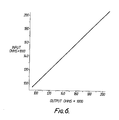
- FIGS. 1 and 2 has demonstrated substantial linearity in the case of resistance-based transducers. As shown in FIG. 6, sensed input, in Kohms, is relatively linear with the indicated output resistance, also in Kohms.
- this advantageously provides an optically powered sensor system in which the value of the measured parameter is obtained as a function of a reference value, and, accordingly, the measurement of the sensed parameter is independent of the energy storage device used in each sensor and is also relatively immune to component value drift.
- the use of short-duration optical pulses results in improved energy utilization in contrast to systems which use pulse width modulation.
Landscapes
- Physics & Mathematics (AREA)
- Electromagnetism (AREA)
- Engineering & Computer Science (AREA)
- Computer Networks & Wireless Communication (AREA)
- Signal Processing (AREA)
- Indication And Recording Devices For Special Purposes And Tariff Metering Devices (AREA)
- Testing Or Calibration Of Command Recording Devices (AREA)
- Measuring Temperature Or Quantity Of Heat (AREA)
- Medicines That Contain Protein Lipid Enzymes And Other Medicines (AREA)
- Arrangements For Transmission Of Measured Signals (AREA)
- Optical Transform (AREA)
- Photometry And Measurement Of Optical Pulse Characteristics (AREA)
- Optical Radar Systems And Details Thereof (AREA)
Applications Claiming Priority (2)
| Application Number | Priority Date | Filing Date | Title |
|---|---|---|---|
| US46075 | 1987-05-05 | ||
| US07/046,075 US4820916A (en) | 1987-05-05 | 1987-05-05 | Optically powered sensor system |
Publications (2)
| Publication Number | Publication Date |
|---|---|
| EP0290243A2 true EP0290243A2 (fr) | 1988-11-09 |
| EP0290243A3 EP0290243A3 (fr) | 1990-01-24 |
Family
ID=21941464
Family Applications (1)
| Application Number | Title | Priority Date | Filing Date |
|---|---|---|---|
| EP88304039A Withdrawn EP0290243A3 (fr) | 1987-05-05 | 1988-05-05 | Système de transducteurs à alimentation optique |
Country Status (6)
| Country | Link |
|---|---|
| US (1) | US4820916A (fr) |
| EP (1) | EP0290243A3 (fr) |
| JP (1) | JP2533912B2 (fr) |
| CA (1) | CA1293298C (fr) |
| DE (1) | DE290243T1 (fr) |
| IL (1) | IL86293A (fr) |
Cited By (10)
| Publication number | Priority date | Publication date | Assignee | Title |
|---|---|---|---|---|
| EP0386965B1 (fr) * | 1989-03-03 | 1994-02-02 | Simmonds Precision Products Inc. | Système de transducteurs à alimentation optique |
| GB2384928A (en) * | 2001-10-19 | 2003-08-06 | Visteon Global Tech Inc | Optical power distribution system |
| US6949758B2 (en) | 2001-10-19 | 2005-09-27 | Visteon Global Technologies, Inc. | LCC-based fluid-level detection sensor |
| WO2006125307A1 (fr) * | 2005-05-23 | 2006-11-30 | Lxsix Photonics Inc. | Procedes et appareils permettant d'obtenir des informations de capteurs dans des voies optiques |
| WO2007002064A1 (fr) * | 2005-06-20 | 2007-01-04 | Halliburton Energy Services, Inc. | Détecteur optique à fibre pouvant utiliser de l’énergie optique pour détecter un paramètre |
| EP2104250A1 (fr) * | 2008-03-18 | 2009-09-23 | Alcatel Lucent | Procédé de surveillance pour réseau optique passif |
| CN101044530B (zh) * | 2004-07-02 | 2010-05-05 | 古河电气工业株式会社 | 光供电型传感系统 |
| RU2633292C2 (ru) * | 2013-06-04 | 2017-10-11 | Сименс Акциенгезелльшафт | Измерение температуры на потенциале высокого напряжения |
| EP3253068A1 (fr) * | 2016-05-20 | 2017-12-06 | Rosemount Aerospace Inc. | Module de transducteur à alimentation optique |
| EP3422607A1 (fr) * | 2017-06-27 | 2019-01-02 | Rolls-Royce Corporation | Puissance et communications sur câblage de fibre optique |
Families Citing this family (30)
| Publication number | Priority date | Publication date | Assignee | Title |
|---|---|---|---|---|
| GB8800972D0 (en) * | 1988-01-16 | 1988-02-17 | Oxley Dev Co Ltd | Sub-sea cable location indicator |
| DE58909254D1 (de) * | 1989-03-17 | 1995-06-29 | Siemens Ag | Autarkes photonengetriebenes Bauelement. |
| US5049825A (en) * | 1989-12-21 | 1991-09-17 | Simmonds Precision Products, Inc. | System and method of error reduction for differential capacitive transducers |
| US5031453A (en) * | 1989-12-21 | 1991-07-16 | Simmonds Precision Products, Inc. | System and method of error reduction for differential capacitive transducers |
| US5258868A (en) * | 1990-02-02 | 1993-11-02 | Rosemount Inc. | Optical process variable transmitter |
| US5134282A (en) * | 1991-02-20 | 1992-07-28 | Cornell Research Foundation, Inc. | Optoelectric sensor and converter |
| DE4116570A1 (de) * | 1991-05-21 | 1992-11-26 | Herion Werke Kg | Verfahren und anordnung zum ansteuern von ventilen |
| IL100528A0 (en) * | 1991-12-26 | 1992-09-06 | Ephraim Secemski | Laser power meter |
| US5223707A (en) * | 1992-06-01 | 1993-06-29 | Honeywell Inc. | Optically powered remote sensor apparatus with synchronizing means |
| US5214274A (en) * | 1992-07-24 | 1993-05-25 | President And Fellows Of Harvard College | Image sensor array with threshold voltage detectors and charged storage capacitors |
| US5528409A (en) * | 1994-10-13 | 1996-06-18 | Nt International, Inc. | Fiber-optic interface system |
| US5771114A (en) * | 1995-09-29 | 1998-06-23 | Rosemount Inc. | Optical interface with safety shutdown |
| US5727110A (en) * | 1995-09-29 | 1998-03-10 | Rosemount Inc. | Electro-optic interface for field instrument |
| US6252689B1 (en) * | 1998-04-10 | 2001-06-26 | Aircuity, Inc. | Networked photonic signal distribution system |
| US6300785B1 (en) | 1998-10-20 | 2001-10-09 | International Business Machines Corporation | Contact-less probe of semiconductor wafers |
| DE10024079A1 (de) * | 2000-05-17 | 2001-11-22 | Asclepion Meditec Ag | Verfahren und Vorrichtung zur Kontrolle der Energie und/oder Position eines gepulsten und gescannten Laserstrahles |
| US6744036B2 (en) * | 2002-10-01 | 2004-06-01 | Simmonds Precision Products, Inc. | Optically coupled sensor for application to combustible liquids |
| US7220990B2 (en) * | 2003-08-25 | 2007-05-22 | Tau-Metrix, Inc. | Technique for evaluating a fabrication of a die and wafer |
| US7263245B2 (en) * | 2005-03-14 | 2007-08-28 | The Boeing Company | Method and apparatus for optically powering and multiplexing distributed fiber optic sensors |
| US8194238B1 (en) * | 2006-02-14 | 2012-06-05 | Killdeer Mountain Manufacturing, Inc. | Optical sensor component identification and interrogation system |
| DE602007004951D1 (de) * | 2007-04-26 | 2010-04-08 | Alcatel Lucent | Optisches Netzwerk, Überwachungseinheit und Überwachungsverfahren |
| US7965948B1 (en) * | 2008-01-04 | 2011-06-21 | Simmonds Precision Products, Inc. | Power and data transmitted over a single optical fiber |
| US8378702B2 (en) | 2009-05-08 | 2013-02-19 | Corning Incorporated | Non-contact testing of printed electronics |
| EP2707766A4 (fr) * | 2011-05-10 | 2015-07-08 | Invensys Sys Inc | Communication optique multipoint |
| US9671279B2 (en) | 2012-12-19 | 2017-06-06 | Zodiac Aerotechnics | Optically-powered sensor systems principally for deployment on-board aircraft and in which optical data is transmitted as available electrical energy permits |
| CN105987772A (zh) * | 2015-02-15 | 2016-10-05 | 无锡汇尔科技有限公司 | 带有光能供电系统的开关柜测温装置 |
| US10598537B2 (en) | 2015-12-17 | 2020-03-24 | Simmonds Precision Products, Inc. | Systems and methods for liquid level detection with optoelectronic interfaced dual thermistor bead sensor |
| US9793991B2 (en) | 2016-03-15 | 2017-10-17 | Simmonds Precision Products, Inc. | Optically interfaced remote data concentrator |
| US11374676B2 (en) * | 2018-06-04 | 2022-06-28 | Telefonaktiebolaget Lm Ericsson (Publ) | Optical device and hub node for an optical network |
| CN113189426B (zh) * | 2021-04-30 | 2024-02-27 | 国网四川省电力公司营销服务中心 | 复合环境下传感器微能量收集装置性能测试方法及系统 |
Family Cites Families (11)
| Publication number | Priority date | Publication date | Assignee | Title |
|---|---|---|---|---|
| USRE27738E (en) * | 1971-12-22 | 1973-08-21 | Takamichi honma | |
| US4281253A (en) * | 1978-08-29 | 1981-07-28 | Optelecom, Inc. | Applications of dual function electro-optic transducer in optical signal transmission |
| SE413808B (sv) * | 1978-09-22 | 1980-06-23 | Asea Ab | Metdon for overforing av metsignaler via en optisk lenk |
| US4346478A (en) * | 1980-12-01 | 1982-08-24 | Siemens Corporation | Fiber optical sensor system, preferably for measuring physical parameters |
| DE3138073A1 (de) * | 1981-09-24 | 1983-04-14 | Siemens AG, 1000 Berlin und 8000 München | Anordnung zur uebertragung von messwerten zu einer entfernten stelle |
| US4436365A (en) * | 1981-10-21 | 1984-03-13 | Bell Telephone Laboratories, Incorporated | Data link using integrated optics devices |
| US4511208A (en) * | 1981-11-26 | 1985-04-16 | Tokyo Shibaura Denki Kabushiki Kaisha | Optical communication system |
| US4490606A (en) * | 1982-04-26 | 1984-12-25 | Geosource Inc. | Transducer apparatus utilizing fiber optics for data transmission |
| GB2144547B (en) * | 1983-08-04 | 1986-10-01 | Gen Electric Plc | A strain sensor |
| US4526027A (en) * | 1983-11-23 | 1985-07-02 | Simmonds Precision Products, Inc. | Pre-calibrated fuel quantity capacitive probe |
| US4641025A (en) * | 1984-12-05 | 1987-02-03 | The Boeing Company | System for determining the position of the boundary between substances having different refractive indices |
-
1987
- 1987-05-05 US US07/046,075 patent/US4820916A/en not_active Expired - Lifetime
-
1988
- 1988-05-04 CA CA000565870A patent/CA1293298C/fr not_active Expired - Lifetime
- 1988-05-05 DE DE198888304039T patent/DE290243T1/de active Pending
- 1988-05-05 IL IL86293A patent/IL86293A/xx unknown
- 1988-05-05 EP EP88304039A patent/EP0290243A3/fr not_active Withdrawn
- 1988-05-06 JP JP63109265A patent/JP2533912B2/ja not_active Expired - Fee Related
Cited By (16)
| Publication number | Priority date | Publication date | Assignee | Title |
|---|---|---|---|---|
| EP0386965B1 (fr) * | 1989-03-03 | 1994-02-02 | Simmonds Precision Products Inc. | Système de transducteurs à alimentation optique |
| GB2384928A (en) * | 2001-10-19 | 2003-08-06 | Visteon Global Tech Inc | Optical power distribution system |
| US6949758B2 (en) | 2001-10-19 | 2005-09-27 | Visteon Global Technologies, Inc. | LCC-based fluid-level detection sensor |
| CN101044530B (zh) * | 2004-07-02 | 2010-05-05 | 古河电气工业株式会社 | 光供电型传感系统 |
| US7672545B2 (en) | 2005-05-23 | 2010-03-02 | Lxdata Inc. | Methods and apparatuses for obtaining information regarding sensors in optical paths |
| WO2006125307A1 (fr) * | 2005-05-23 | 2006-11-30 | Lxsix Photonics Inc. | Procedes et appareils permettant d'obtenir des informations de capteurs dans des voies optiques |
| WO2007002064A1 (fr) * | 2005-06-20 | 2007-01-04 | Halliburton Energy Services, Inc. | Détecteur optique à fibre pouvant utiliser de l’énergie optique pour détecter un paramètre |
| WO2009115421A1 (fr) * | 2008-03-18 | 2009-09-24 | Alcatel Lucent | Procédé de surveillance pour un réseau optique passif |
| EP2104250A1 (fr) * | 2008-03-18 | 2009-09-23 | Alcatel Lucent | Procédé de surveillance pour réseau optique passif |
| US8625987B2 (en) | 2008-03-18 | 2014-01-07 | Alcatel Lucent | Monitoring method for a passive optical network |
| RU2633292C2 (ru) * | 2013-06-04 | 2017-10-11 | Сименс Акциенгезелльшафт | Измерение температуры на потенциале высокого напряжения |
| US9945733B2 (en) | 2013-06-04 | 2018-04-17 | Siemens Aktiengesellschaft | Temperature measurement at high-voltage potential |
| EP3253068A1 (fr) * | 2016-05-20 | 2017-12-06 | Rosemount Aerospace Inc. | Module de transducteur à alimentation optique |
| US9906300B2 (en) | 2016-05-20 | 2018-02-27 | Rosemount Aerospace Inc. | Optically powered transducer module |
| EP3422607A1 (fr) * | 2017-06-27 | 2019-01-02 | Rolls-Royce Corporation | Puissance et communications sur câblage de fibre optique |
| US10313026B2 (en) | 2017-06-27 | 2019-06-04 | Rolls-Royce North American Technologies, Inc. | Power and communications over fiber optic cabling |
Also Published As
| Publication number | Publication date |
|---|---|
| JPS6453113A (en) | 1989-03-01 |
| JP2533912B2 (ja) | 1996-09-11 |
| US4820916A (en) | 1989-04-11 |
| DE290243T1 (de) | 1989-03-30 |
| IL86293A (en) | 1991-01-31 |
| IL86293A0 (en) | 1988-11-15 |
| CA1293298C (fr) | 1991-12-17 |
| EP0290243A3 (fr) | 1990-01-24 |
Similar Documents
| Publication | Publication Date | Title |
|---|---|---|
| EP0290243A2 (fr) | Système de transducteurs à alimentation optique | |
| US4963729A (en) | Optically powered sensor system with improved signal conditioning | |
| US4346478A (en) | Fiber optical sensor system, preferably for measuring physical parameters | |
| JPS6398099A (ja) | センサ装置からの信号の伝送方法 | |
| US5007042A (en) | Method and apparatus for transmitting analog data embedded in a digital pulse train | |
| US5644222A (en) | Process for testing an electronic electricity meter | |
| US4947033A (en) | Voltage/frequency converter and its use in an optical wave guide transmission arrangement | |
| US4866436A (en) | Device for transmitting measurement values of a sensor | |
| CA2310583A1 (fr) | Commande d'elements chauffants | |
| EP0165697B1 (fr) | Dispositif de capteur optique | |
| US4864648A (en) | Method of transmitting a group at least two measured values through an optical transmission path | |
| US4643568A (en) | Method and apparatus for measuring the illuminating power of incident light | |
| EP0053391A1 (fr) | Système de capteurs à fibre optique, de préférence pour application dans les équipements d'automobile | |
| EP0212898B1 (fr) | Convertisseur analogique-numérique | |
| RU95116011A (ru) | Оптическая система связи | |
| EP0657719A2 (fr) | Système de capteur optique multiple | |
| EP0368454B1 (fr) | Commande pour débitmètres à tourbillon à fibres optiques | |
| JPS5745741A (en) | Signal transmitter | |
| JPH01314399A (ja) | 光結合リモートセンサー装置 | |
| EP0293441B1 (fr) | Ameliorations apportees a des systemes de detection optique | |
| SU516088A1 (ru) | Передающее радиотелеметрическое устройство | |
| SU1003379A2 (ru) | Устройство дл передачи бипол рных телеграфных сигналов | |
| SU894863A1 (ru) | Преобразователь частоты в напр жение | |
| SU1381570A1 (ru) | Устройство дл телеизмерений | |
| SU995327A2 (ru) | Устройство дл формировани измерительных импульсов |
Legal Events
| Date | Code | Title | Description |
|---|---|---|---|
| PUAI | Public reference made under article 153(3) epc to a published international application that has entered the european phase |
Free format text: ORIGINAL CODE: 0009012 |
|
| AK | Designated contracting states |
Kind code of ref document: A2 Designated state(s): DE FR GB IT |
|
| ITCL | It: translation for ep claims filed |
Representative=s name: MODIANO & ASSOCIATI S.R.L. |
|
| EL | Fr: translation of claims filed | ||
| DET | De: translation of patent claims | ||
| PUAL | Search report despatched |
Free format text: ORIGINAL CODE: 0009013 |
|
| AK | Designated contracting states |
Kind code of ref document: A3 Designated state(s): DE FR GB IT |
|
| STAA | Information on the status of an ep patent application or granted ep patent |
Free format text: STATUS: THE APPLICATION IS DEEMED TO BE WITHDRAWN |
|
| 18D | Application deemed to be withdrawn |
Effective date: 19900725 |