EP0290355B1 - Falttürenantriebsvorrichtung für Fahrkörbe von Aufzügen - Google Patents
Falttürenantriebsvorrichtung für Fahrkörbe von Aufzügen Download PDFInfo
- Publication number
- EP0290355B1 EP0290355B1 EP88420117A EP88420117A EP0290355B1 EP 0290355 B1 EP0290355 B1 EP 0290355B1 EP 88420117 A EP88420117 A EP 88420117A EP 88420117 A EP88420117 A EP 88420117A EP 0290355 B1 EP0290355 B1 EP 0290355B1
- Authority
- EP
- European Patent Office
- Prior art keywords
- leaf
- door
- disc
- leaves
- vertical
- Prior art date
- Legal status (The legal status is an assumption and is not a legal conclusion. Google has not performed a legal analysis and makes no representation as to the accuracy of the status listed.)
- Expired - Lifetime
Links
Images
Classifications
-
- B—PERFORMING OPERATIONS; TRANSPORTING
- B66—HOISTING; LIFTING; HAULING
- B66B—ELEVATORS; ESCALATORS OR MOVING WALKWAYS
- B66B13/00—Doors, gates, or other apparatus controlling access to, or exit from, cages or lift well landings
- B66B13/02—Door or gate operation
- B66B13/06—Door or gate operation of sliding doors
- B66B13/08—Door or gate operation of sliding doors guided for horizontal movement
Definitions
- the present invention relates to an accordion-type door drive mechanism for elevator cars.
- Accordion-type elevator doors consist of two half-doors, each of which has two leaves hinged to each other by their adjacent vertical edges, one of these two leaves being hinged by its other vertical edge, on a fixed vertical axis located in the vicinity of one of the sides of the cabin opening, while the free edge of the other leaf is guided in translation by a roller of vertical axis engaged in a horizontal slide parallel to the plan of the cabin opening.
- the first type of these mechanisms acts on each inner leaf, that is to say not articulated on a fixed axis, parallel to the plane of the opening, in one direction or the other according to that he controls the opening or closing of the door.
- This type of linear mechanism which implements a simple kinematics, compact and easy to accommodate, without overflow, on the roof of a cabin, has the disadvantage that in the closed position of the door, the leaves necessarily occupy , but in pure loss, part of the interior volume of the cabin.
- the second type of these mechanisms acts by rotating the axes of which the outer or leading leaves are integral.
- this mechanism comprises, articulated on two crank pins carried by a circular drive plate of vertical axis situated in the median transverse plane of the opening, two rods, each of which is articulated, by its other end, on a crank wedged on the hinge axis of one of the outer leaves; the drive plate is pivoted by about half a turn in one direction or the other, depending on whether it controls the opening or closing of the door, which gives the links a pseudo-translation movement of sinusoidal type which slows the movement of their ends articulated to the crankpins, at the end of opening or closing of the door.
- this second type of mechanism allows the door to be fully opened and closed, but it has the major drawback in the open position of the door, several parts of the mechanism protrude laterally from the cabin and constitute a nuisance during certain maintenance or repair operations.
- European patent application 0 195 101 describes an alternative embodiment of this second type of mechanism which, like the previous one, comprises, in association with each pair of ventaux, a circular drive plate whose vertical axis is located substantially on the bisector of the angle of approximately 90 ° swept by the external fan or leading from the half-door considered, and which is located above this fan.
- each plate carries a pivoting slide engaged on a lever arm articulated on a vertical fixed axis situated behind the pivot axis of the plate in question, and the other end of which itself carries a slide engaged on a horizontal slide, secured to the outer fan of the pair in question.
- the present invention aims to remedy all these drawbacks by providing a mechanism or operator which allows total opening and closing of the door, while being completely roomy, without overflowing, on the roof of the cabin.
- each circular plate carries, on the side of its lower face, a vertical drive finger engaged in a light of longitudinal axis parallel to the plane of this leaf, near the upper edge. of the latter and which is formed in a part which is integral therewith, the diameter of the circle described by the drive finger being determined so that, when it performs, with its support plate, a rotation of an angle between 180 and 270 °, the leading leaf is itself rotated from one to the other of its extreme positions corresponding to the opening and closing positions of the door.
- Each drive plate can therefore be placed entirely and without overflowing on the roof of the cabin.
- each drive finger is advantageously between 190 and 250 °.
- the two extreme positions of the drive finger are symmetrical with respect to the bisector of the angle of approximately 90 ° swept by the leading leaf.
- one of the drive plates is coupled to a gear motor placed on the roof of the cabin and the second plate is linked to it in reverse rotation by a crossed endless cable. and with which mooring means are associated with each of the plates.
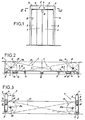
- the mechanism of the invention is intended to control the opening and closing of the door of an elevator car 2, this door being of the accordion type, that is to say made up of two half doors 3 and 4 each of which comprises two leaves 5 and 6 articulated to one another by one of their adjacent vertical edges, that is to say along a vertical axis 7; the outer leaf 5 or leading from each of these half-doors 3 and 5, that is to say the one located closest to one of the sides of the access opening 8 of the cabin 2, is hinged on a fixed vertical axis 9 located in the vicinity of the corresponding side of this opening 8, while each inner leaf 6 or led is guided by the engagement of the upper end 10, possibly constituted by a roller, with its free edge in a horizontal slide parallel to the plane of the opening 8 and not shown in the drawing.
- the four leaves 5 and 6 in the closed position, the four leaves 5 and 6 must be located in the same plane parallel to that of the opening 8, while in the open position of the door, the four leaves 5 and 6 must be folded in pairs against each other, so as to completely release the opening 8.
- the present invention aims to achieve this result without the mechanism, placed on the roof of the cabin 2, that is to say above the opening 8, having the slightest overflow relative to the roof of the cabin .
- this mechanism comprises, in association with each half-door 3 and 4, a circular drive plate, respectively 11 and 12, whose vertical axis, respectively 11 a and 12a, is located on the bisector, respectively 13 and 14, of the angle swept by the outer leaf 5 considered when it passes from one to the other of its extreme positions corresponding to the closed and open positions of the door 3,4 from cabin 2.
- the angle swept by the outer leaves 5 is 90 ° .
- Each tray 11, 12 is located on the roof of the cabin 2, above the corresponding half-door, respectively, 3 and 4 and it drives, directly or not, a drive finger 15, located on the side of its underside and engaged in a slot 16 whose longitudinal axis is parallel to the plane of the leaf 5 considered and which is formed in a part or part integral with this leaf 5.
- each plate 11 and 12 is capable of being rotated around its axis, respectively 11 a, 12a, over a stroke of 190 ° during which each finger d drive 15 is moved from one extreme position to another and these two extreme positions are symmetrical with respect to the bisector 13 or 14 by the angle swept by the corresponding external leaf 5.
- This arrangement is made compulsory by the symmetry of the arrangement of each plate 11 and 12 with respect to the angle swept by the leaf 5 with which it is associated.
- each slot 16 is obviously established to allow the necessary movement of the corresponding drive finger 15 during the opening or closing operation of the leaf 5 in the slot 16 of which it is engaged.
- FIG 2 shows the doors 3, 4 in the closed position and, to bring this door in the open position as illustrated in Figure 3, it is necessary that the plates 11 and 12 are rotated over a stroke slightly greater than 180 ° in the direction of the arrows, respectively 18 and 19, that is to say in the opposite direction with respect to each other.
- the outer leaves 5 are pivoted by a quarter of a turn in the same direction as their respective plate, around their axes of articulation 9. During from this pivoting, they drive the leaf 6 which is associated with them so as to bring it into the open position of the door 3,4, position in which each internal leaf 6 is folded against the external leaf or associated leading 5.
- the drive fingers 15 integral with the drive plates 11 and 12 are located on a radius of the plate considered such that at the end of each of the rotational strokes of the associated plate 11 or 12, it is brought closer to the end of the light 16 closest to the corresponding articulation axis 9 of the leaf 5 considered. Thanks to this arrangement, when the door 3, 4 is in the closed position as illustrated in FIG. 3, each drive finger 15 acts, via the light 16 in which it is engaged, on the leaf 5 which associated with it, in the direction of arrow 21 which is oriented tangentially to the plate 11 or 12 considered, at the point of implantation of this drive finger 15.
- the mechanism of the invention therefore makes it possible to achieve the desired result of allowing total clearance of the opening 8 of the cabin 2 in the door opening position 3,4, as well as placing in the same plane , parallel to that of the opening 8, of all the leaves 5 and 6 in the closed position of the door 3,4, without, however, one of the constituent parts of this mechanism projecting beyond the roof of the cabin 2 on which it is placed.
- the cable 23 is positively linked to each plate 11 and 12 by any suitable known means such as nuts or the like .
- this mechanism is reversible, so that it is possible to maneuver the door 3,4 in the opening direction and, consequently, to eliminate any risk of asphyxiation in cabin 2 in the event engine failure or power outage.
Landscapes
- Power-Operated Mechanisms For Wings (AREA)
- Elevator Door Apparatuses (AREA)
- Folding Of Thin Sheet-Like Materials, Special Discharging Devices, And Others (AREA)
- Extensible Doors And Revolving Doors (AREA)
- Organic Insulating Materials (AREA)
- Organic Low-Molecular-Weight Compounds And Preparation Thereof (AREA)
- Liquid Carbonaceous Fuels (AREA)
Claims (5)
Priority Applications (1)
| Application Number | Priority Date | Filing Date | Title |
|---|---|---|---|
| AT88420117T ATE59180T1 (de) | 1987-05-05 | 1988-04-12 | Falttuerenantriebsvorrichtung fuer fahrkoerbe von aufzuegen. |
Applications Claiming Priority (2)
| Application Number | Priority Date | Filing Date | Title |
|---|---|---|---|
| FR8706681 | 1987-05-05 | ||
| FR8706681A FR2614885B1 (fr) | 1987-05-05 | 1987-05-05 | Mecanisme d'entrainement de portes de type accordeon pour cabines d'ascenseurs |
Publications (2)
| Publication Number | Publication Date |
|---|---|
| EP0290355A1 EP0290355A1 (de) | 1988-11-09 |
| EP0290355B1 true EP0290355B1 (de) | 1990-12-19 |
Family
ID=9351031
Family Applications (1)
| Application Number | Title | Priority Date | Filing Date |
|---|---|---|---|
| EP88420117A Expired - Lifetime EP0290355B1 (de) | 1987-05-05 | 1988-04-12 | Falttürenantriebsvorrichtung für Fahrkörbe von Aufzügen |
Country Status (6)
| Country | Link |
|---|---|
| EP (1) | EP0290355B1 (de) |
| AT (1) | ATE59180T1 (de) |
| DE (1) | DE3861299D1 (de) |
| ES (1) | ES2019472B3 (de) |
| FR (1) | FR2614885B1 (de) |
| PT (1) | PT87397B (de) |
Cited By (5)
| Publication number | Priority date | Publication date | Assignee | Title |
|---|---|---|---|---|
| US10470428B2 (en) | 2018-03-07 | 2019-11-12 | Basf Agricultural Solutions Seed, Us Llc | Cotton variety ST 5471GLTP |
| US11076548B2 (en) | 2018-03-07 | 2021-08-03 | Basf Agricultural Solutions Seed, Us Llc | Cotton variety ST 5122GLT |
| US11213003B2 (en) | 2019-02-12 | 2022-01-04 | BASF Agricultural Solutions Seed US LLC | Cotton variety ST 4550GLTP |
| US11234407B2 (en) | 2019-02-12 | 2022-02-01 | BASF Agricultural Solutions Seed US LLC | Cotton variety FM 1621GL |
| US11284595B2 (en) | 2019-02-12 | 2022-03-29 | BASF Agricultural Solutions Seed US LLC | Cotton variety FM 2398GLTP |
Families Citing this family (4)
| Publication number | Priority date | Publication date | Assignee | Title |
|---|---|---|---|---|
| FR2639338B1 (fr) * | 1988-11-22 | 1991-02-15 | France Logique Ascenseurs | Operateur pour porte a battant a fermeture et ouverture automatiques et porte le comportant |
| JP2006298621A (ja) * | 2005-04-22 | 2006-11-02 | Mitsubishi Electric Corp | エレベータの制御盤 |
| SE532706C2 (sv) | 2007-06-18 | 2010-03-23 | Motala Hissar Ab | Motoriserad hissdörr |
| US12121002B2 (en) | 2021-02-24 | 2024-10-22 | BASF Agricultural Solutions Seed US LLC | Cotton variety FM 1730GLTP |
Family Cites Families (4)
| Publication number | Priority date | Publication date | Assignee | Title |
|---|---|---|---|---|
| DE2507967A1 (de) * | 1968-12-12 | 1976-09-02 | Kauffmann Maschbau Herbert | Drehfalttor |
| GB2039595B (en) * | 1979-01-10 | 1982-10-20 | Bostwick Doors Uk Ltd | Closure structures |
| EP0195101B1 (de) * | 1985-03-20 | 1989-05-24 | Carl Sigerist AG | Falttüre mit elastischer Füllung |
| FR2595677B1 (fr) * | 1986-03-17 | 1988-07-01 | Kone Ste Fse Ascenseurs | Porte pour cabine de monte-charges |
-
1987
- 1987-05-05 FR FR8706681A patent/FR2614885B1/fr not_active Expired
-
1988
- 1988-04-12 AT AT88420117T patent/ATE59180T1/de not_active IP Right Cessation
- 1988-04-12 DE DE8888420117T patent/DE3861299D1/de not_active Expired - Fee Related
- 1988-04-12 EP EP88420117A patent/EP0290355B1/de not_active Expired - Lifetime
- 1988-04-12 ES ES88420117T patent/ES2019472B3/es not_active Expired - Lifetime
- 1988-05-03 PT PT87397A patent/PT87397B/pt not_active IP Right Cessation
Cited By (5)
| Publication number | Priority date | Publication date | Assignee | Title |
|---|---|---|---|---|
| US10470428B2 (en) | 2018-03-07 | 2019-11-12 | Basf Agricultural Solutions Seed, Us Llc | Cotton variety ST 5471GLTP |
| US11076548B2 (en) | 2018-03-07 | 2021-08-03 | Basf Agricultural Solutions Seed, Us Llc | Cotton variety ST 5122GLT |
| US11213003B2 (en) | 2019-02-12 | 2022-01-04 | BASF Agricultural Solutions Seed US LLC | Cotton variety ST 4550GLTP |
| US11234407B2 (en) | 2019-02-12 | 2022-02-01 | BASF Agricultural Solutions Seed US LLC | Cotton variety FM 1621GL |
| US11284595B2 (en) | 2019-02-12 | 2022-03-29 | BASF Agricultural Solutions Seed US LLC | Cotton variety FM 2398GLTP |
Also Published As
| Publication number | Publication date |
|---|---|
| DE3861299D1 (de) | 1991-01-31 |
| PT87397B (pt) | 1993-09-30 |
| ES2019472B3 (es) | 1991-06-16 |
| EP0290355A1 (de) | 1988-11-09 |
| FR2614885A1 (fr) | 1988-11-10 |
| FR2614885B1 (fr) | 1989-06-30 |
| PT87397A (pt) | 1989-05-31 |
| ATE59180T1 (de) | 1991-01-15 |
Similar Documents
| Publication | Publication Date | Title |
|---|---|---|
| EP1240042B1 (de) | In einem kraftfahrzeugkofferraum versenkbares dach | |
| EP1349743B1 (de) | Klappverdeck für fahrzeug mit gleitelementen | |
| EP0290355A1 (de) | Falttürenantriebsvorrichtung für Fahrkörbe von Aufzügen | |
| EP1369276A1 (de) | Hintere Haube für Kraftfahrzeug | |
| FR2866314A1 (fr) | Trappe de train d'atterrissage a cinematique controlee | |
| EP0198760A1 (de) | Vorrichtung zum Öffnen und Schliessen mit Verriegelung von Doppelflügeltüren für Drahtseilbahnkabinen | |
| FR2752011A1 (fr) | Dispositif d'ouverture et de fermeture d'une fenetre de vehicule | |
| EP0465281B1 (de) | Schiebetür und ihr Antriebsmechanismus | |
| EP1470012B1 (de) | Kofferraumdeckel für ein cabriofahrzeug mit faltverdeck | |
| EP2694306B2 (de) | Glasdach mit verschiebbarer und schwenkbarer mobiler platte | |
| FR2827628A1 (fr) | Dispositif de protection du mecanisme de soulevement et d'abaissement de la porte de passagers d'un avion | |
| FR3017827A1 (fr) | Pavillon vitre a panneau mobile entrebaillant et coulissant en position deflectrice | |
| FR2596726A1 (fr) | Porte d'un appareil volant | |
| EP1277607B1 (de) | Fahrerkabine einer Baumaschine mit einer Vorrichtung zum Öffnen und Schliessen einer Tür, und Baumaschine mit einer solchen Fahrerkabine | |
| EP0876946B1 (de) | Türschliesser, damit ausgerüstete Tür und Schienenfahrzeug mit mindestens einer derartigen Vorrichtung und/oder Tür | |
| FR2625991A1 (fr) | Dispositif d'entrainement d'une porte de cabine d'ascenseur | |
| FR3014932A1 (fr) | Porte pliante | |
| EP2457756B1 (de) | Verglaster Pavillon mit beweglichen Schiebe- und Öffnungspaneelen | |
| FR2929317A1 (fr) | Porte de garage et ensemble comportant une telle porte | |
| EP0329535B1 (de) | Schwenkbare Schleusenschranke zur Sicherung der Plattform | |
| EP0370879B1 (de) | Türschliesser für eine Schwingtür mit automatischer Öffnung und Schliessung und eine Tür, die damit ausgerüstet ist | |
| FR2740505A1 (fr) | Charniere pour porte d'automobile | |
| FR2970439A1 (fr) | Toit ouvrant en porte-a-faux au-dessus d'un pavillon de vehicule automobile | |
| BE1004004A6 (fr) | Porte de garage. | |
| EP1077147A1 (de) | Schiebetüranordnung an einem Fahrzeug |
Legal Events
| Date | Code | Title | Description |
|---|---|---|---|
| PUAI | Public reference made under article 153(3) epc to a published international application that has entered the european phase |
Free format text: ORIGINAL CODE: 0009012 |
|
| AK | Designated contracting states |
Kind code of ref document: A1 Designated state(s): AT BE CH DE ES GB GR IT LI LU NL SE |
|
| 17P | Request for examination filed |
Effective date: 19881014 |
|
| 17Q | First examination report despatched |
Effective date: 19900302 |
|
| GRAA | (expected) grant |
Free format text: ORIGINAL CODE: 0009210 |
|
| RAP3 | Party data changed (applicant data changed or rights of an application transferred) |
Owner name: SOCIETE LYONNAISE DE CONSTRUCTION DE MATERIEL D'AS |
|
| AK | Designated contracting states |
Kind code of ref document: B1 Designated state(s): AT BE CH DE ES GB GR IT LI LU NL SE |
|
| PG25 | Lapsed in a contracting state [announced via postgrant information from national office to epo] |
Ref country code: SE Free format text: THE PATENT HAS BEEN ANNULLED BY A DECISION OF A NATIONAL AUTHORITY Effective date: 19901219 Ref country code: NL Effective date: 19901219 Ref country code: GR Free format text: LAPSE BECAUSE OF FAILURE TO SUBMIT A TRANSLATION OF THE DESCRIPTION OR TO PAY THE FEE WITHIN THE PRESCRIBED TIME-LIMIT Effective date: 19901219 |
|
| REF | Corresponds to: |
Ref document number: 59180 Country of ref document: AT Date of ref document: 19910115 Kind code of ref document: T |
|
| ITF | It: translation for a ep patent filed | ||
| GBT | Gb: translation of ep patent filed (gb section 77(6)(a)/1977) | ||
| REF | Corresponds to: |
Ref document number: 3861299 Country of ref document: DE Date of ref document: 19910131 |
|
| PG25 | Lapsed in a contracting state [announced via postgrant information from national office to epo] |
Ref country code: LU Free format text: LAPSE BECAUSE OF NON-PAYMENT OF DUE FEES Effective date: 19910430 Ref country code: LI Effective date: 19910430 Ref country code: CH Effective date: 19910430 Ref country code: BE Effective date: 19910430 |
|
| NLV1 | Nl: lapsed or annulled due to failure to fulfill the requirements of art. 29p and 29m of the patents act | ||
| PLBE | No opposition filed within time limit |
Free format text: ORIGINAL CODE: 0009261 |
|
| STAA | Information on the status of an ep patent application or granted ep patent |
Free format text: STATUS: NO OPPOSITION FILED WITHIN TIME LIMIT |
|
| BERE | Be: lapsed |
Owner name: SOC. LYONNAISE DE CONSTRUCTION DE MATERIEL D'ASCEN Effective date: 19910430 |
|
| 26N | No opposition filed | ||
| REG | Reference to a national code |
Ref country code: CH Ref legal event code: PL |
|
| ITTA | It: last paid annual fee | ||
| PGFP | Annual fee paid to national office [announced via postgrant information from national office to epo] |
Ref country code: GB Payment date: 19940324 Year of fee payment: 7 |
|
| PGFP | Annual fee paid to national office [announced via postgrant information from national office to epo] |
Ref country code: DE Payment date: 19940329 Year of fee payment: 7 |
|
| PGFP | Annual fee paid to national office [announced via postgrant information from national office to epo] |
Ref country code: ES Payment date: 19940414 Year of fee payment: 7 |
|
| PGFP | Annual fee paid to national office [announced via postgrant information from national office to epo] |
Ref country code: AT Payment date: 19940429 Year of fee payment: 7 |
|
| PG25 | Lapsed in a contracting state [announced via postgrant information from national office to epo] |
Ref country code: GB Effective date: 19950412 Ref country code: AT Effective date: 19950412 |
|
| PG25 | Lapsed in a contracting state [announced via postgrant information from national office to epo] |
Ref country code: ES Free format text: LAPSE BECAUSE OF NON-PAYMENT OF DUE FEES Effective date: 19950415 |
|
| GBPC | Gb: european patent ceased through non-payment of renewal fee |
Effective date: 19950412 |
|
| PG25 | Lapsed in a contracting state [announced via postgrant information from national office to epo] |
Ref country code: DE Effective date: 19960103 |
|
| REG | Reference to a national code |
Ref country code: ES Ref legal event code: FD2A Effective date: 19990201 |
|
| PG25 | Lapsed in a contracting state [announced via postgrant information from national office to epo] |
Ref country code: IT Free format text: LAPSE BECAUSE OF NON-PAYMENT OF DUE FEES;WARNING: LAPSES OF ITALIAN PATENTS WITH EFFECTIVE DATE BEFORE 2007 MAY HAVE OCCURRED AT ANY TIME BEFORE 2007. THE CORRECT EFFECTIVE DATE MAY BE DIFFERENT FROM THE ONE RECORDED. Effective date: 20050412 |