EP0290403A1 - Heavy vehicle, particularly a bus - Google Patents
Heavy vehicle, particularly a bus Download PDFInfo
- Publication number
- EP0290403A1 EP0290403A1 EP88830183A EP88830183A EP0290403A1 EP 0290403 A1 EP0290403 A1 EP 0290403A1 EP 88830183 A EP88830183 A EP 88830183A EP 88830183 A EP88830183 A EP 88830183A EP 0290403 A1 EP0290403 A1 EP 0290403A1
- Authority
- EP
- European Patent Office
- Prior art keywords
- motor vehicle
- auxiliary frame
- chassis
- drive
- differential unit
- Prior art date
- Legal status (The legal status is an assumption and is not a legal conclusion. Google has not performed a legal analysis and makes no representation as to the accuracy of the status listed.)
- Withdrawn
Links
- 239000000725 suspension Substances 0.000 claims abstract description 17
- 230000005540 biological transmission Effects 0.000 claims description 16
- 239000006096 absorbing agent Substances 0.000 description 2
- 208000032369 Primary transmission Diseases 0.000 description 1
Images

Classifications
-
- B—PERFORMING OPERATIONS; TRANSPORTING
- B60—VEHICLES IN GENERAL
- B60G—VEHICLE SUSPENSION ARRANGEMENTS
- B60G9/00—Resilient suspensions of a rigid axle or axle housing for two or more wheels
- B60G9/02—Resilient suspensions of a rigid axle or axle housing for two or more wheels the axle or housing being pivotally mounted on the vehicle, e.g. the pivotal axis being parallel to the longitudinal axis of the vehicle
- B60G9/027—Resilient suspensions of a rigid axle or axle housing for two or more wheels the axle or housing being pivotally mounted on the vehicle, e.g. the pivotal axis being parallel to the longitudinal axis of the vehicle the axle having either a triangular, a "T" or "U" shape and being directly articulated with the chassis only by its middle apex, e.g. De Dion suspension
-
- B—PERFORMING OPERATIONS; TRANSPORTING
- B60—VEHICLES IN GENERAL
- B60K—ARRANGEMENT OR MOUNTING OF PROPULSION UNITS OR OF TRANSMISSIONS IN VEHICLES; ARRANGEMENT OR MOUNTING OF PLURAL DIVERSE PRIME-MOVERS IN VEHICLES; AUXILIARY DRIVES FOR VEHICLES; INSTRUMENTATION OR DASHBOARDS FOR VEHICLES; ARRANGEMENTS IN CONNECTION WITH COOLING, AIR INTAKE, GAS EXHAUST OR FUEL SUPPLY OF PROPULSION UNITS IN VEHICLES
- B60K17/00—Arrangement or mounting of transmissions in vehicles
- B60K17/34—Arrangement or mounting of transmissions in vehicles for driving both front and rear wheels, e.g. four wheel drive vehicles
Definitions
- the present invention relates to a heavy motor vehicle, particularly a bus, including: - a chassis - at least one front live axle, - at least one rear live axle, - a front transmission shaft, - a rear transmission shaft, - a transmission box from which the front and rear transmission shafts extend and which receives the drive from an engine-gearbox unit, and - a differential unit associated with each live axle, which receives the drive through one of the transmission shafts and from which extend two drive-shafts for transmitting the drive to the respective wheels of the motor vehicle.
- a frame for the suspension of the driving wheels of heavy vehicles is also known, which has a triangular shape in plan and is pivotably connected to the chassis of the vehicle in correspondence with one vertex.
- the transmission layout provides a differential unit for each live axle, connected rigidly to the suspension frame.
- a suspension frame of this type is not suitable for use in a bus since, in order to avoid interference between the differential unit and the body of the vehicle when the vehicle is jolted, the floor level of the bus would have to be positioned very high off the ground and this would involve considerable inconvenience for the passengers boarding and alighting from the bus.
- the object of the present invention is to apply to a heavy vehicle, particularly to a bus, a suspension layout which enables a substantial lowering of the floor level of the vehicle.
- each differential unit is rigidly connected to the chassis of the vehicle, and in which each pair of driving wheels of the vehicle is supported by an auxiliary suspension frame having a triangular shape in plan with two inclined sides arranged symmetrically with respect to the median plane of the motor vehicle and a third side arranged transverse that plane, the auxiliary frame being pivotably connected to the chassis of the motor vehicle in correspondence with its vertex which is situated in the median plane of the motor vehicle, and also having a central aperture in correspondence with which the respective differential unit is situated so as to avoid any interference between the auxiliary frame and the differential unit when the suspension is jolted.
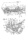
- a bus is generally indicated 1 and is provided with a chassis 2 having a lattice structure.
- the transmission system of the bus 1 includes an engine-gearbox unit 3 and a primary transmission shaft 4 which takes the drive from the output shaft of the gearbox 5 and supplies it to a transmission box 6.
- the box 6 includes a bevel gear 7 and a differential 8 for dividing the drive between a front live axle 9 and a rear live axle 10.
- a front transmission shaft 11 and a rear transmission shaft 12 extend from the differential 8 and transmit the drive to a front differential unit 13 and a rear differential unit 14, respectively.
- An important characteristic of the present invention consists of the fact that the two differential units 13 and 14 are rigidly connected to the chassis 2 of the vehicle. Pairs of drive-shafts, indicated 15 and 16 respectively, which transmit the drive to the wheels 17 and 18, extend from each of the two differential units 13 and 14.
- the front wheels 17 are supported by an auxiliary suspension frame 19 having a triangular shape in plan.
- the auxiliary frame 19 comprises two inclined sides 20 arranged symmetrically with respect to the median plane of the motor vehicle, and a side 21 arranged transverse that plane, the sides 20 and 21 defining a central aperture 22 in correspondence with which the differential unit 13 is situated.
- the aperture 22 is shaped so as to avoid any interference between the auxiliary frame 19 and the differential unit 13 when the suspension is jolted.
- the vertex defined by the two sides 20 carries a bush 23 for articulation to the chassis 2.
- the connection of the bush 23 to the chassis 2 is effected by means of a rubber support whose deformation allows differentiated jolting of the wheels 17 in a transverse plane.
- the auxiliary frame 19 Adjacent each of the two vertices formed by the two inclined sides 20 and the transverse side 21, the auxiliary frame 19 has a support pillar 24 with a forked appendage 25 for the attachment of the wheels 17.
- the top portion 26 of the pillar 24 has a hole 27 for the attachment of an air spring the other end of which is connected to the chassis 2.
- the two pillars 24 are also provided with through-holes 29 through which the drive-shafts 15 pass.
- the frame 19 carries four brackets 30 each for the attachment of one end of a shock-absorber 31 whose other end is connected to the chassis 2.
- the side 21 of the auxiliary frame 19 is provided with an end 32 to which is articulated the end of a transverse bar 33 having its other end articulated to the chassis 2 and intended to withstand the transverse thrusts which act on the suspension.
- the side 21 is also provided with two brackets 34 to which are articulated the ends of a U-shaped bar 35 the central part of which constitutes a torsion bar supported by the chassis 2 in a freely rotatable manner by means of two rods 36.
- the rear suspension of the bus 1 is illustrated in Figure 4.
- This comprises an auxiliary frame 37 substantially similar to the auxiliary frame 19 described above, having an attachment bush 38 arranged forward of the axis of the wheels 18.
- Two parts 39 for the attachment of air springs are connected to the auxiliary frame 37.
- Four shock-absorbers 40, a transverse bar 41 and an anti-roll bar 42 are also provided for the rear suspension.
- differential units 13 and 14 are positioned within the apertures provided in the auxiliary frames 19 and 37, it is possible to produce a vehicle which has a particularly low floor level.
Landscapes
- Engineering & Computer Science (AREA)
- Mechanical Engineering (AREA)
- Chemical & Material Sciences (AREA)
- Combustion & Propulsion (AREA)
- Transportation (AREA)
- Body Structure For Vehicles (AREA)
- Vehicle Body Suspensions (AREA)
Applications Claiming Priority (2)
| Application Number | Priority Date | Filing Date | Title |
|---|---|---|---|
| IT6737687 | 1987-04-30 | ||
| IT67376/87A IT1218655B (it) | 1987-04-30 | 1987-04-30 | Schema di trasmissione integrale per veicoli industriali ed autobus |
Publications (1)
| Publication Number | Publication Date |
|---|---|
| EP0290403A1 true EP0290403A1 (en) | 1988-11-09 |
Family
ID=11301881
Family Applications (1)
| Application Number | Title | Priority Date | Filing Date |
|---|---|---|---|
| EP88830183A Withdrawn EP0290403A1 (en) | 1987-04-30 | 1988-04-29 | Heavy vehicle, particularly a bus |
Country Status (2)
| Country | Link |
|---|---|
| EP (1) | EP0290403A1 (it) |
| IT (1) | IT1218655B (it) |
Cited By (1)
| Publication number | Priority date | Publication date | Assignee | Title |
|---|---|---|---|---|
| CN112208281A (zh) * | 2020-10-30 | 2021-01-12 | 奇瑞万达贵州客车股份有限公司 | 一种基于全承载式城市客车后空气悬架的结构 |
Citations (8)
| Publication number | Priority date | Publication date | Assignee | Title |
|---|---|---|---|---|
| FR767749A (fr) * | 1933-02-03 | 1934-07-23 | Daimler Benz Ag | Dispositif de montage des essieux, en particulier pour voitures automobiles |
| FR1284180A (fr) * | 1961-02-28 | 1962-02-09 | Davey Compressor Co | Mécanisme de transmission pour véhicules automobiles |
| GB1082992A (en) * | 1965-06-29 | 1967-09-13 | County Commercial Cars Ltd | Improvements in or relating to wheel mountings for motor vehicles |
| DE1580327A1 (de) * | 1965-06-02 | 1970-01-29 | Maschf Augsburg Nuernberg Ag | Starrachsanordnung,insbesondere fuer schwere gelaendegaengige Kraftfahrzeuge |
| GB1347109A (en) * | 1970-04-02 | 1974-02-27 | Chrysler France | Rearwheel suspension of the rigid-axle type for vehicles |
| FR2319507A1 (fr) * | 1975-07-28 | 1977-02-25 | Peugeot | Train arriere a essieu rigide, pour vehicule |
| US4362221A (en) * | 1978-01-19 | 1982-12-07 | Manning Donald L | Vehicle drive wheel suspension |
| GB2139971A (en) * | 1983-05-16 | 1984-11-21 | Maschf Augsburg Nuernberg Ag | Axle suspension for a vehicle |
-
1987
- 1987-04-30 IT IT67376/87A patent/IT1218655B/it active
-
1988
- 1988-04-29 EP EP88830183A patent/EP0290403A1/en not_active Withdrawn
Patent Citations (8)
| Publication number | Priority date | Publication date | Assignee | Title |
|---|---|---|---|---|
| FR767749A (fr) * | 1933-02-03 | 1934-07-23 | Daimler Benz Ag | Dispositif de montage des essieux, en particulier pour voitures automobiles |
| FR1284180A (fr) * | 1961-02-28 | 1962-02-09 | Davey Compressor Co | Mécanisme de transmission pour véhicules automobiles |
| DE1580327A1 (de) * | 1965-06-02 | 1970-01-29 | Maschf Augsburg Nuernberg Ag | Starrachsanordnung,insbesondere fuer schwere gelaendegaengige Kraftfahrzeuge |
| GB1082992A (en) * | 1965-06-29 | 1967-09-13 | County Commercial Cars Ltd | Improvements in or relating to wheel mountings for motor vehicles |
| GB1347109A (en) * | 1970-04-02 | 1974-02-27 | Chrysler France | Rearwheel suspension of the rigid-axle type for vehicles |
| FR2319507A1 (fr) * | 1975-07-28 | 1977-02-25 | Peugeot | Train arriere a essieu rigide, pour vehicule |
| US4362221A (en) * | 1978-01-19 | 1982-12-07 | Manning Donald L | Vehicle drive wheel suspension |
| GB2139971A (en) * | 1983-05-16 | 1984-11-21 | Maschf Augsburg Nuernberg Ag | Axle suspension for a vehicle |
Cited By (1)
| Publication number | Priority date | Publication date | Assignee | Title |
|---|---|---|---|---|
| CN112208281A (zh) * | 2020-10-30 | 2021-01-12 | 奇瑞万达贵州客车股份有限公司 | 一种基于全承载式城市客车后空气悬架的结构 |
Also Published As
| Publication number | Publication date |
|---|---|
| IT1218655B (it) | 1990-04-19 |
| IT8767376A0 (it) | 1987-04-30 |
Similar Documents
| Publication | Publication Date | Title |
|---|---|---|
| EP0287278B1 (en) | A vehicle chassis transverse structural member | |
| US4474389A (en) | Axle suspension for a passenger motor vehicle | |
| US2751992A (en) | Unit power plant and axle unit suspension in motor vehicles | |
| US4343375A (en) | Vehicle drive wheel suspension | |
| DE68905581T2 (de) | Unabhaengige hinterradaufhaengung. | |
| US2689015A (en) | Axle suspension for motor vehicles | |
| US3327803A (en) | Independent rear wheel suspension | |
| US4362221A (en) | Vehicle drive wheel suspension | |
| US2080969A (en) | Automobile vehicle having independently-sprung road wheels | |
| US3177965A (en) | Link type independent wheel suspension for vehicles | |
| US2145670A (en) | Swinging half-axle suspension | |
| EP0301782A2 (en) | Vehicle wheel suspension unit | |
| US2062233A (en) | Vehicle wheel suspension | |
| US4451054A (en) | Vehicle suspension system | |
| EP0290403A1 (en) | Heavy vehicle, particularly a bus | |
| US2200798A (en) | Motor vehicle | |
| US2137848A (en) | Automobile chassis | |
| US4046212A (en) | Steerable front wheel drive transmitting mechanism | |
| EP0087270B1 (en) | Improvements to the mounting of power unit and suspension assemblies in front wheel drive vehicles | |
| US3948336A (en) | Vehicle suspension system | |
| CN217260289U (zh) | 一种无人驾驶线控底盘的后悬架结构 | |
| HU212319B (en) | Axle with longitudinal arms for motor vehicles and trailers | |
| US4875705A (en) | Automobile rear suspension structure | |
| US4355696A (en) | Axle suspension for the driven axle of a road vehicle | |
| US3149689A (en) | Motor vehicle drive assemblies |
Legal Events
| Date | Code | Title | Description |
|---|---|---|---|
| PUAI | Public reference made under article 153(3) epc to a published international application that has entered the european phase |
Free format text: ORIGINAL CODE: 0009012 |
|
| AK | Designated contracting states |
Kind code of ref document: A1 Designated state(s): AT BE CH DE ES FR GB GR IT LI LU NL SE |
|
| 17P | Request for examination filed |
Effective date: 19890502 |
|
| 17Q | First examination report despatched |
Effective date: 19901004 |
|
| RAP1 | Party data changed (applicant data changed or rights of an application transferred) |
Owner name: PERFORMANCE TECHNOLOGY OF ITALY - ALBA TECH S.R.L |
|
| STAA | Information on the status of an ep patent application or granted ep patent |
Free format text: STATUS: THE APPLICATION IS DEEMED TO BE WITHDRAWN |
|
| 18D | Application deemed to be withdrawn |
Effective date: 19910626 |