EP0291202A1 - Dispositif de nettoyage - Google Patents
Dispositif de nettoyage Download PDFInfo
- Publication number
- EP0291202A1 EP0291202A1 EP88303891A EP88303891A EP0291202A1 EP 0291202 A1 EP0291202 A1 EP 0291202A1 EP 88303891 A EP88303891 A EP 88303891A EP 88303891 A EP88303891 A EP 88303891A EP 0291202 A1 EP0291202 A1 EP 0291202A1
- Authority
- EP
- European Patent Office
- Prior art keywords
- tank
- liquid
- article
- kegs
- articles
- Prior art date
- Legal status (The legal status is an assumption and is not a legal conclusion. Google has not performed a legal analysis and makes no representation as to the accuracy of the status listed.)
- Withdrawn
Links
- 238000004140 cleaning Methods 0.000 title claims abstract description 30
- 239000007788 liquid Substances 0.000 claims abstract description 34
- 239000002783 friction material Substances 0.000 claims abstract description 6
- 238000005096 rolling process Methods 0.000 claims description 7
- 238000001914 filtration Methods 0.000 claims description 4
- XLYOFNOQVPJJNP-UHFFFAOYSA-N water Substances O XLYOFNOQVPJJNP-UHFFFAOYSA-N 0.000 abstract description 23
- 235000013405 beer Nutrition 0.000 abstract description 4
- 239000000463 material Substances 0.000 description 2
- 239000002184 metal Substances 0.000 description 2
- 239000011324 bead Substances 0.000 description 1
- 239000000969 carrier Substances 0.000 description 1
- 238000010276 construction Methods 0.000 description 1
- 239000003599 detergent Substances 0.000 description 1
- 239000012530 fluid Substances 0.000 description 1
- 239000011888 foil Substances 0.000 description 1
- 239000013505 freshwater Substances 0.000 description 1
- 238000012423 maintenance Methods 0.000 description 1
- 230000004048 modification Effects 0.000 description 1
- 238000012986 modification Methods 0.000 description 1
- 230000002093 peripheral effect Effects 0.000 description 1
- 239000004033 plastic Substances 0.000 description 1
- 229920003023 plastic Polymers 0.000 description 1
- 230000001681 protective effect Effects 0.000 description 1
- 239000010802 sludge Substances 0.000 description 1
- 239000007787 solid Substances 0.000 description 1
- 239000007921 spray Substances 0.000 description 1
- 230000003019 stabilising effect Effects 0.000 description 1
- 239000003381 stabilizer Substances 0.000 description 1
- 238000011144 upstream manufacturing Methods 0.000 description 1
- 238000005406 washing Methods 0.000 description 1
- 239000002699 waste material Substances 0.000 description 1
Images


Classifications
-
- B—PERFORMING OPERATIONS; TRANSPORTING
- B08—CLEANING
- B08B—CLEANING IN GENERAL; PREVENTION OF FOULING IN GENERAL
- B08B9/00—Cleaning hollow articles by methods or apparatus specially adapted thereto
- B08B9/08—Cleaning containers, e.g. tanks
- B08B9/0804—Cleaning containers having tubular shape, e.g. casks, barrels, drums
Definitions
- This invention relates to cleaning apparatus and has a particularly useful but not exclusive application in cleaning the external surfaces of metal barrels such as beer kegs.
- cleaning apparatus comprising a tank for a cleaning liquid, means for emitting sound waves of ultrasonic frequency into the liquid in the tank, and means in the tank for supporting and rotating an article such that the whole or substantially the whole of the external surface of the article is, or passes, below the level of the liquid and is subjected to a cleaning action.
- cleaning apparatus comprising a tank containing a cleaning liquid, means for emitting sound waves of ultrasonic frequency below the level of the liquid in the tank and means for rotating an article partly immersed in the liquid, so that the whole external surface of the article passes below the level of the liquid.
- the invention also provides cleaning apparatus comprising a tank containing a cleaning liquid, means in the liquid for emitting ultrasonic waves, and means for rotating an article partly immersed in the liquid and for simultaneously moving the article along the tank.
- said means for emitting sound waves is so disposed that the whole of the external surface of the article is, or comes into, direct "view" of the emitting means.
- said means for rotating the article and for simultaneously moving the article operates continuously to convey a succession of the articles along the tank.
- the means for simultaneously rotating and moving the articles along the tank comprises a plurality of pusher elements moving in an endless path which includes a run generally parallel to the surface of the cleaning liquid and a fixed surface extending lengthwise of the tank with which surface the articles move in direct rolling contact.
- said fixed surface is conveniently disposed above the surface of the liquid so that the buoyancy of the articles causes them to be pressed against said fixed surface.
- the pusher elements may conveniently be rollers arranged for rolling engagement with a circumferential surface of the articles.
- a filter tank containing a filtering apparatus and having in a side wall thereof a weir through which liquid from the first said (main) tank enters the filter tank, and means for adjusting the height of the weir so as to maintain the vertical distance between the weir and the level of the liquid in the filter tank constant.
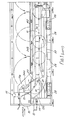
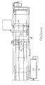
- the apparatus shown is designed to clean the external surfaces of empty beer kegs.
- the kegs 10 are passed in succession along an elongate tank 11 containing a cleaning fluid, usually hot water, up to a level 12.
- the kegs are passed from an apparatus which is described in British Patent Application No. 8613963 and which serves to tip the kegs into a rolling attitude.
- the kegs roll along a guideway 13 which extends over one end wall 14 of the tank and is then inclined downward to lower the kegs into the water.
- the kegs are prevented from rolling freely into the water by pairs of drive rollers 15 which move between the kegs and by hinged weighted stabiliser bars 20, 21 which engage the kegs from above and below respectively to steady the kegs and prevent them from tilting or turning during their downward movement.
- the drive rollers 15 are mounted on shafts 16 opposite ends of which are attached to parallel endless chains 17 extending about sprockets 18 and driven by a variable speed motor 19.
- the pairs of rollers 15 move between the kegs at the upper end of the downwardly inclined section 13a of the guideway to separate the kegs, and then push the kegs along the tank.
- a pair of upper bars is mounted on the tank structure and includes a downwardly-inclined inlet section 24a, a horizontal section 24b disposed above the water and an upwardly inclined outlet section 24c.
- the inlet section 24a extends in a curve leading smoothly into the horizontal section 24b, the underside of which has a friction material secured to it.
- the horizontal section 24b is spaced above the water surface 12 by a distance such that the axis of the keg is substantially coincident with the water surface.
- the buoyancy of the keg presses it against the friction material on the horizontal section, which causes the keg to spin, and the length of the tank and the friction material is made sufficient to ensure that the whole of the external surface of each keg passes through the water as the keg moves along the tank.
- the rollers 15 are in low-friction contact with the kegs.
- a series of ultrasonic transducers 28 which operate to produce high cavitation in the water directly between the transducer and the part of the surface of the keg facing the transducer as the keg passes over each transducer, producing a highly effective cleaning action on that part of the surface.
- the activated length of the tank, the rotation of the keg as it moves along the tank and the close proximity of the keg to transducers thus ensure that the whole circumference of the keg is cleaned.
- similar transducers may be mounted on the side walls of the tank.
- a manifold pipe 30 extends along each side wall of the tank and has a series of jets along its length through which hot water from the tank is sprayed on to the end walls of the kegs.
- Rails 32 forming a continuation of rails 13a extend horizontally between the kegs and the ultrasonic transducers in order to protect the latter and at the outlet end of the tank the rails 32 and the outlet section 24c of the bars are inclined upward and the kegs are thus released from the holding down action of the bars, but are restrained from rapid movement resulting from the buoyancy forces by the rollers 15 and by hinged weighted stabilising bars 33 which rest against the upper surface of each keg as it rises out of the water.
- the rails 32 continue generally horizontally and then down a shallow incline, along which the kegs are driven by the rollers 15.
- inwardly inclined track elements 34 act against peripheral beads on the keg to centralise it.
- the rollers 15 drive the kegs to a rinsing station 36 at which hot clarified water is sprayed onto the kegs from manifolds 37 to remove the detergent film and any loose foreign matter still on the kegs.
- hot clean water from high pressure pumps is sprayed at high velocity from manifolds 39 on to the neck or end other areas of the kegs from which labels are to be removed.
- a weighted lever 38 hinged at its upstream end to the frame of the apparatus and having a low-friction material 38a on its lower surface is arranged to press down on each passing keg to press the keg into engagement with a high-friction surface of twin belts 40 the upper runs of which are moving in the opposite direction to the keg, so as to cause the keg to spin.
- the length of the rinsing station is less than the circumferential length of the kegs and this arrangement ensures that each keg rotates through substantially one full revolution while passing the manifolds 39 without the need to lengthen the rinsing station and to increase the number of rinsing jets. All debris at this station is removed by a driven transverse horizontal filter belt 41 which is continuously washed clean by cold water spray jets.
- the kegs are finally returned to an upright attitude by a turning device as described in Patent Application No. 8613963.
- the tank is provided with removable hinged covers 11a, and a protective canopy 42 extends over the full length of the cleaning apparatus.
- Drain valves 44 are provided for draining the various tanks and sludge doors 45 enable accumulated debris to be removed from the tanks when they have been drained.
- Side guide bars for the kegs may be provided to extend along the tank if desired.
- the illustrated apparatus has been found to provide a very effective cleaning action on the external surfaces of beer kegs which have been returned for re-filling. It has been found that it is important that metal surfaces which are to be cleaned by ultrasonic action should have a direct 'view' of the ultrasonic transducers.
- the apparatus also deals effectively with the problem of buoyancy forces, which may amount to 300lb. on a fully immersed keg.
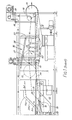
- the illustrated apparatus includes an automatic filtering device mounted in a side tank 43 into which water from the main tank 11 flows for cleaning and subsequent return to the main tank.
- the tank 43 has one of its side walls formed with a horizontally elongate slot 46 through which the water to be filered enters from the main tank 11.
- the bottom edge of the slot constitutes a weir.
- An endless filter belt 47 extending across the full width of tank 43 and driven by a motor 48 extends generally in the form of an inverted V, one arm 49 of which is disposed in the tank 43, the other arm 50 overhanging a receptacle 51 for debris washed off the belt.
- the arm 49 has its upper run 52 disposed generally below the weir.
- the belt 47 and the two side walls of the tank define a filter chest 53 from which water which has flowed through the runs of the arm 49 is drawn out of the chest by a circulating pump and returned to the manifolds 30 in the main washing tank 11 through a pipe 54.
- the debris deposited on the belt is carried over to the other arm 50 where fresh water from a nozzle 56 disposed above the lower run washes the debris off the belt into the receptacle 51 where a sieve 57 traps larger elements of debris, the remainder being passed to waste through an outlet 58.
- the weir is in the form of a curved plate 60 hinged along one horizontal edge to the side wall of the tank; plate 60 is connected to a float 61 which is disposed under the plate so as to prevent debris from falling directly on to the float.
- a float 61 which is disposed under the plate so as to prevent debris from falling directly on to the float.
- the water flowing towards the weir entrains debris with it and the maintenance of a flow over the weir into the tank assists in maintaining uniform entrainment of debris and in maintaining a constant velocity of flow of the water on to the filter belt and efficient removal of the debris from the cleaning tank 11.
- Seals are preferably provided between the side edges of the plate and the side walls of the tank, so as to prevent leakage past the weir. Such seals may be in the form of concertina-like strips of rubber, plastics material, foil or other suitable material. A further seal may be provided which enables the weir plate 60 to close off and seal the slot 46 if desired.
Landscapes
- Engineering & Computer Science (AREA)
- Mechanical Engineering (AREA)
- Cleaning By Liquid Or Steam (AREA)
Applications Claiming Priority (4)
| Application Number | Priority Date | Filing Date | Title |
|---|---|---|---|
| GB8710355 | 1987-05-01 | ||
| GB878710355A GB8710355D0 (en) | 1987-05-01 | 1987-05-01 | Weirs |
| GB878710354A GB8710354D0 (en) | 1987-05-01 | 1987-05-01 | Cleaning apparatus |
| GB8710354 | 1987-05-01 |
Publications (1)
| Publication Number | Publication Date |
|---|---|
| EP0291202A1 true EP0291202A1 (fr) | 1988-11-17 |
Family
ID=26292195
Family Applications (1)
| Application Number | Title | Priority Date | Filing Date |
|---|---|---|---|
| EP88303891A Withdrawn EP0291202A1 (fr) | 1987-05-01 | 1988-04-29 | Dispositif de nettoyage |
Country Status (1)
| Country | Link |
|---|---|
| EP (1) | EP0291202A1 (fr) |
Cited By (2)
| Publication number | Priority date | Publication date | Assignee | Title |
|---|---|---|---|---|
| EP2285504A4 (fr) * | 2008-05-08 | 2013-07-31 | Cavitus Pty Ltd | Procédés et appareil de nettoyage par ultrasons |
| CN115382846A (zh) * | 2022-10-31 | 2022-11-25 | 山东省蓬莱制药机械厂有限公司 | 一种西林瓶内外壁高洁度清洗机 |
Citations (5)
| Publication number | Priority date | Publication date | Assignee | Title |
|---|---|---|---|---|
| US3352723A (en) * | 1962-07-17 | 1967-11-14 | Universal Container Corp | Method of cleaning used steel drums of organic residues |
| GB2124598A (en) * | 1982-08-05 | 1984-02-22 | Lea Joanne Mary | Cleaning machines |
| EP0125054A2 (fr) * | 1983-04-22 | 1984-11-14 | Mcg Techno Pack Limited | Méthode et appareil pour nettoyer des conteneurs réutilisables |
| DE3340509A1 (de) * | 1983-09-07 | 1985-03-21 | Heinz 65719 Hofheim Till | Verfahren und vorrichtung zum reinigen eines fasses |
| GB2154973A (en) * | 1984-02-24 | 1985-09-18 | Techno Pack Ltd | Conveying through ultrasonic washing apparatus |
-
1988
- 1988-04-29 EP EP88303891A patent/EP0291202A1/fr not_active Withdrawn
Patent Citations (5)
| Publication number | Priority date | Publication date | Assignee | Title |
|---|---|---|---|---|
| US3352723A (en) * | 1962-07-17 | 1967-11-14 | Universal Container Corp | Method of cleaning used steel drums of organic residues |
| GB2124598A (en) * | 1982-08-05 | 1984-02-22 | Lea Joanne Mary | Cleaning machines |
| EP0125054A2 (fr) * | 1983-04-22 | 1984-11-14 | Mcg Techno Pack Limited | Méthode et appareil pour nettoyer des conteneurs réutilisables |
| DE3340509A1 (de) * | 1983-09-07 | 1985-03-21 | Heinz 65719 Hofheim Till | Verfahren und vorrichtung zum reinigen eines fasses |
| GB2154973A (en) * | 1984-02-24 | 1985-09-18 | Techno Pack Ltd | Conveying through ultrasonic washing apparatus |
Cited By (2)
| Publication number | Priority date | Publication date | Assignee | Title |
|---|---|---|---|---|
| EP2285504A4 (fr) * | 2008-05-08 | 2013-07-31 | Cavitus Pty Ltd | Procédés et appareil de nettoyage par ultrasons |
| CN115382846A (zh) * | 2022-10-31 | 2022-11-25 | 山东省蓬莱制药机械厂有限公司 | 一种西林瓶内外壁高洁度清洗机 |
Similar Documents
| Publication | Publication Date | Title |
|---|---|---|
| CA1082076A (fr) | Appareil et methode de nettoyage de cotenants | |
| US7727336B2 (en) | Glass washing machine with broken glass removal system | |
| US3886959A (en) | Glass washing machine | |
| US4061152A (en) | Container washing apparatus | |
| EP0095119A2 (fr) | Machine à grand rendement pour le nettoyage de paillassons | |
| US4918778A (en) | Endless rotary band cleaning device, particularly for cleaning a conveyor belt or supporting surfaces of objects | |
| EP0125054B1 (fr) | Méthode et appareil pour nettoyer des conteneurs réutilisables | |
| US4042507A (en) | Waste liquid renovator | |
| US3347378A (en) | Filter apparatus | |
| EP0291202A1 (fr) | Dispositif de nettoyage | |
| US3372811A (en) | Rotating drum filter apparatus | |
| AU663544B2 (en) | Improvements in or relating to belt filters | |
| US3506022A (en) | Conveyor filter apparatus for article washing apparatus | |
| US2846704A (en) | Washer for pickles or the like | |
| US3044474A (en) | Egg washer | |
| US6189703B1 (en) | Endless media filtration system | |
| US2217689A (en) | Filtering system, device used therein, and method of filtration | |
| CN215649164U (zh) | 一种绿叶类新鲜蔬菜预处理用清洁装置 | |
| CN216944739U (zh) | 纤维输送的防污装置 | |
| SU1134247A1 (ru) | Установка дл струйной очистки поверхности изделий | |
| US2189586A (en) | Bottle washer and sterilizer | |
| JPH07303881A (ja) | 浮上油除去方法及び装置 | |
| SU1161651A1 (ru) | Устройство дл удалени плавающих веществ с поверхности жидкости | |
| SU1657243A1 (ru) | Конвейерна установка дл очистки изделий | |
| CN117085999A (zh) | 一种中药饮片加工用中药泡洗装置 |
Legal Events
| Date | Code | Title | Description |
|---|---|---|---|
| PUAI | Public reference made under article 153(3) epc to a published international application that has entered the european phase |
Free format text: ORIGINAL CODE: 0009012 |
|
| AK | Designated contracting states |
Kind code of ref document: A1 Designated state(s): AT BE CH DE ES FR GB GR IT LI LU NL SE |
|
| 17P | Request for examination filed |
Effective date: 19890505 |
|
| 17Q | First examination report despatched |
Effective date: 19890705 |
|
| STAA | Information on the status of an ep patent application or granted ep patent |
Free format text: STATUS: THE APPLICATION HAS BEEN WITHDRAWN |
|
| 18W | Application withdrawn |
Withdrawal date: 19900130 |
|
| R18W | Application withdrawn (corrected) |
Effective date: 19900130 |