EP0292016A2 - Composant de réglage, en particulier pour un potentiomètre linéaire - Google Patents
Composant de réglage, en particulier pour un potentiomètre linéaire Download PDFInfo
- Publication number
- EP0292016A2 EP0292016A2 EP88108165A EP88108165A EP0292016A2 EP 0292016 A2 EP0292016 A2 EP 0292016A2 EP 88108165 A EP88108165 A EP 88108165A EP 88108165 A EP88108165 A EP 88108165A EP 0292016 A2 EP0292016 A2 EP 0292016A2
- Authority
- EP
- European Patent Office
- Prior art keywords
- guide element
- sliding
- sliding body
- elongated hole
- actuator
- Prior art date
- Legal status (The legal status is an assumption and is not a legal conclusion. Google has not performed a legal analysis and makes no representation as to the accuracy of the status listed.)
- Granted
Links
Images


Classifications
-
- H—ELECTRICITY
- H01—ELECTRIC ELEMENTS
- H01C—RESISTORS
- H01C10/00—Adjustable resistors
- H01C10/30—Adjustable resistors the contact sliding along resistive element
- H01C10/38—Adjustable resistors the contact sliding along resistive element the contact moving along a straight path
Definitions
- the invention relates to an actuator, in particular for linear potentiometers according to the preamble of claim 1.
- Such an actuator is known from DE-OS 26 27 346.
- the guide element and the sliding body are made of different plastics, which differ in particular in terms of their softening temperature.
- the guide element is produced, which is then inserted into an injection mold and thus itself forms part of the injection mold, the sliding body then being injection molded onto the guide element in a further injection molding process.
- the guide element has in all cases one or more grooves in which which the sliding body is held in a form-fitting manner with a thickening or widening (see FIGS. 8 and 10 of DE-OS 26 27 346).
- actuators used in linear potentiometers which are commercially available, are constructed so that the actuators have a guide element with an elongated hole, in which a sliding body is slidably guided.
- the sliding body which carries the sliding contact springs on a potentiometer as a so-called spring support, is secured as security against falling out of the elongated hole by inserted pins which are inserted into a bore in the sliding body and protrude laterally beyond the elongated hole.
- the guide element with an elongated hole on the one hand and the sliding body on the other hand were each manufactured separately and then assembled together. In these known actuators, it is disadvantageous that the tolerances to be observed increase the manufacturing effort.
- the sliding body If the sliding body is "too tight” to the guide element and the elongated hole, it slides, if at all, only with difficulty and not smoothly. If, on the other hand, the adjustment is "too loose", the sliding body can on the one hand tilt and thus jam during its movement and on the other hand it is no longer guided with sufficient precision so that, for example, in the case of a linear potentiometer between the mechanical position of the sliding body relative to the guide element and the electrical setting Resistance value there is no clearly reproducible relationship. When manufacturing these actuators must therefore be very tight Manufacturing tolerances are met, which in turn is complex. Even then, the tolerances set in each production can still add up in an unfavorable direction, so that the risk of reject production is still relatively great.
- the object of the invention is therefore to improve the actuator of the type mentioned in such a way that the sliding properties of the actuator are further improved.
- This object is achieved in the generic actuator by the features of claim 1.
- Advantageous refinements and developments of the invention can be found in the subclaims.
- those parts of the sliding body that serve as guide elements are injection-molded in such a way that no unfavorable distortions or bending occur when the plastic is shrunk. You also get multi-point bearings of the sliding body on the guide element, with which tilting or jamming of the sliding body is prevented even more effectively, while simultaneously reducing the frictional forces, taking into account the peculiarities of injection molding technology, in particular with regard to cooling behavior, shrinkage and formation of voids.
- Actuators of the type dealt with here are used in the most varied fields of technology, for example as a displaceable spring support in Linear potentiometers, as contact carriers in slide switches, as actuators for mechanical cam controls, as actuators for sensors, etc.
- harsh environmental conditions such as dust, oil or other dirt, as well as strong temperature fluctuations and icing.
- Such environmental conditions occur, for example, when used in motor vehicles when linear potentiometers are used as measuring sensors for sensing the throttle valve position or as other measuring sensors, for example for level control, headlight range adjustment, etc. Due to the special design of the actuator according to the invention, it still works perfectly even with dirt, icing, etc. (of course only to a certain degree).
- the sliding body is in one piece, so that assembly steps are eliminated and the problem of dimensional tolerances is solved satisfactorily. Even if the thickness of the guide element or the width of the elongated hole fluctuate within large tolerances, the "molded" sliding body is individually adapted to the associated guide element, since the latter is part of the injection mold. Dimensional inaccuracies of the guide element have no negative influence. Dimensional tolerances cannot add up unfavorably.
- shrinkage or shrinkage of 0.5 to 1% occurs. This is very desirable in the invention, since this shrinking provides the necessary bearing play which allows the sliding body to be displaced relative to the guide element. This play of 0.5 to 1%, which occurs with most sprayable plastics during shrinking, has turned out to be the optimal play, which allows extremely precise guidance, prevents tilting and also moves the sliding body in the event of dirt or icing allowed.
- FIGS. 1 to 9 show different variants of a linear actuator, each of which has a plate-shaped guide element 1 with a rectilinear elongated hole 2, which here is rectangular in plan view.
- the guide element 1 can be a metal sheet from which the elongated hole is punched out. It can also be made of a high-melting (i.e. melting at high temperature) plastic.
- the mutually facing sides of the elongated hole extending in the longitudinal direction of the elongated hole 2 form guide surfaces 3 and 4 for a sliding body 7 which projects from the top 5 of the guide element 1 through the elongated hole 2 to the underside 6 of the guide element.
- the sliding body 7 has a section 8 which is immersed in the elongated hole 2 and whose side walls 9 and 10 are guided on the guide surfaces 3 and 4, respectively.
- a "bearing play" which arises in the manufacturing process according to the invention in that during the injection molding process the plastic is injected into parts of the elongated hole in accordance with the other shape of the sliding body, the guide surfaces 3 and 4 of the elongated hole serve as a shape, the plastic then shrinking during the subsequent hardening, specifically by about 0.5 to 1%.
- the total play i.e. the sum of the distances between the surfaces 4 and 9 and 3 and 10, is always 0.5 to 1% of the width of the elongated hole.
- section 8 running in the interior of the elongated hole 2 is in principle cuboid in the illustrated exemplary embodiments.
- section 8 is of course adapted to this contour.
- the section can be approximately cylindrical, so that it can run in the elongated hole thus curved without tilting. In this case, the injection mold must ensure that it is approximately cylindrical.
- the sliding body 7 also has a base 11 lying outside the elongated hole, on which in some cases the sliding segments are attached in one piece and to which an actuating lever 12 of any shape is also attached.
- This operating lever can also be made in the injection mold or screwed on, glued, etc. later.
- FIGS. 1 to 9 match.
- the deviations will now be described below.
- a total of six sliding segments 13, 14, 15, 16, 17 and 18 are provided.
- sliding elements 13, 14, 15 and 16 are provided, which at both ends (in relation to the longitudinal direction of the elongated hole) project laterally beyond the elongated hole, so that - one presses the base 11 into the plane of the drawing in FIG. 2 into it - the guide element rests on four surfaces on the top 5 of the guide element 1.
- On the underside 6 of the sliding body on the other hand, only two sliding segments 17 and 18 are provided, which are seen in the longitudinal direction of the sliding body and are arranged approximately in the middle thereof.
- the sliding body is therefore prevented from tipping or rotating about the three possible tilting or rotating axes with respect to the guide element 1 by the six surfaces of the sliding segments 13 to 18 and by the side surfaces 9 and 10 of section 8 (FIG. 8) secured.
- the guidance through the sliding segments is still relatively rigid, so that unevenness in the guide element or foreign bodies, dirt or ice, even of a small thickness, can impair the displaceability of the sliding body.
- the second exemplary embodiment of the invention according to FIGS. 3 and 4 only provides four-point support. Seen in the direction of sliding of the sliding body, there are two laterally projecting sliding segments 13 and 14 at one end on the upper side 5, while sliding segments 17 and 18 are located on the lower side 6 at the other end. In the top view of Figure 4 it can be clearly seen that the sliding segments do not overlap on the top and bottom. Rather, the sliding segments 13 and 17 on the one hand and the sliding segments 14 and 18 on the other hand are at a distance from one another in the top view in FIG. However, the sliding body against tilting or twisting about an axis which lies in the plane of the guide element 1 and perpendicular to the longitudinal extent of the slot 2 is still possible.
- the sliding body can be rotated about an axis perpendicular to the plane of the drawing in FIG. 3, namely from the limit position in FIG. 3, in which the four sliding segments rest on the guide element, a clockwise rotation is possible.
- a tension spring 19 is provided on the bottom 6 is stretched between two pins 20 and 21, one pin 20 being fastened to the sliding body, specifically in the plan view of FIG. 4 lying approximately between the sliding segments 13 and 14, while the other pin 21 is fastened to the guide element 1.
- This tension spring is - even if the sliding body is at one end of the elongated hole 2 at the stop, under a prestress, so that a torque acts on the sliding body, which requires tilting in the counterclockwise direction.
- the spring 19 also acts here as a return spring, which pulls the sliding body into a limit position, which is required for applications with sensors.
- shrinking of the plastic during curing in a direction perpendicular to the plane of the guide element does not result in any contact forces that could brace the sliding segments against the guide element.
- Figures 5 to 9 builds on the embodiment of Figures 3 and 4. It differs from the latter, however, in that a web 22, 23, 24 and 25 is formed on the sliding segments 13, 14, 17 and 18, which runs parallel to the elongation of the elongated hole 2, but offset laterally with respect to the elongated hole is so that it is in sliding contact with the top or bottom 5 or 6 of the guide element.
- these webs run in a ramp shape, that is to say they have an incline 26 rising from their free end in the direction of the associated sliding segment to, so that they overlap in pairs (22, 24 and 23, 25) seen in the side view (Fig.5). Tipping is no longer possible, as in the example of FIGS. 3 and 4.
- This embodiment is also shown with a spring 19 and pin 20, 21.
- this spring 19 acts primarily as a return spring and only secondarily also applies a torque, as is required in the exemplary embodiment in FIGS. 3 and 4. If no return spring is required in the exemplary embodiment in FIGS. 5 to 9, the spring 19 can be omitted without further notice, without the risk of tilting or tilting of the sliding body.
- the entire sliding body, including the sliding segments and the webs 22 to 25 is produced in one operation as an injection molded part.
- a further variant, not shown, relates to a modification of the exemplary embodiment in FIGS. 1 and 2.
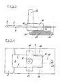
- FIGS. 5 to 9 show a linear potentiometer with return spring, in which the actuator according to the invention is used, namely essentially the actuator according to the embodiment of FIGS. 5 to 9.
- This linear potentiometer has a resistance plate 27 which is fastened in a housing 29 and has resistance tracks on one side. Parallel to this resistance plate, the guide element 1 is also fastened in the housing 29, the slide body 7 serving here as a spring support for wiper springs 28 which are in sliding contact with the resistance tracks of the resistance plate 27. 10 shows the two limit positions of the sliding body. The rest position is shown with solid lines, while another limit position assumed against the force of the springs 19 is shown in dashed lines.
- the actuating lever 12 is designed here as an inclined pushbutton, with which adjustment movements of a unit to be scanned are transmitted to the sliding body 7, which executes a linear adjustment stroke in accordance with the scanned position.
- the usual connection or soldering lugs are attached to one end of the resistance plate 27, by means of which the potentiometer can be tapped electrically.
Landscapes
- Engineering & Computer Science (AREA)
- Microelectronics & Electronic Packaging (AREA)
- Injection Moulding Of Plastics Or The Like (AREA)
- Moulds For Moulding Plastics Or The Like (AREA)
- Measurement Of Length, Angles, Or The Like Using Electric Or Magnetic Means (AREA)
- Adjustable Resistors (AREA)
Applications Claiming Priority (2)
| Application Number | Priority Date | Filing Date | Title |
|---|---|---|---|
| DE19873717117 DE3717117A1 (de) | 1987-05-21 | 1987-05-21 | Verfahren zur herstellung eines stellgliedes, insbesondere fuer linearpotentiometer sowie nach dem verfahren hergestelltes stellglied |
| DE3717117 | 1987-05-21 |
Publications (3)
| Publication Number | Publication Date |
|---|---|
| EP0292016A2 true EP0292016A2 (fr) | 1988-11-23 |
| EP0292016A3 EP0292016A3 (en) | 1990-06-20 |
| EP0292016B1 EP0292016B1 (fr) | 1993-10-20 |
Family
ID=6328078
Family Applications (1)
| Application Number | Title | Priority Date | Filing Date |
|---|---|---|---|
| EP88108165A Expired - Lifetime EP0292016B1 (fr) | 1987-05-21 | 1988-05-20 | Composant de réglage, en particulier pour un potentiomètre linéaire |
Country Status (2)
| Country | Link |
|---|---|
| EP (1) | EP0292016B1 (fr) |
| DE (2) | DE3717117A1 (fr) |
Families Citing this family (3)
| Publication number | Priority date | Publication date | Assignee | Title |
|---|---|---|---|---|
| DE3731328C1 (de) * | 1987-09-17 | 1989-01-12 | Ruf Kg Wilhelm | Potentiometer und Verfahren zu dessen Herstellung |
| DE4428273C2 (de) * | 1994-08-10 | 1997-06-12 | Siedle Horst Kg | Linearer Wegaufnehmer |
| DE102005028849B4 (de) | 2005-06-22 | 2021-11-18 | Kostal Automobil Elektrik Gmbh & Co. Kg | Anordnung mit wenigstens zwei in ihrer Form aneinander angepaßten und linear gegeneinander beweglichen Teilen |
Family Cites Families (3)
| Publication number | Priority date | Publication date | Assignee | Title |
|---|---|---|---|---|
| US3156804A (en) * | 1962-05-31 | 1964-11-10 | Gen Electric | Slidable switch mechanism for an electric toothbrush |
| US3732521A (en) * | 1971-05-03 | 1973-05-08 | Mallory & Co Inc P R | Mounting means and slideable electrical contact for linear potentiometer |
| JPS51151753A (en) * | 1975-06-20 | 1976-12-27 | Matsushita Electric Industrial Co Ltd | Method of producing resin product with slide |
-
1987
- 1987-05-21 DE DE19873717117 patent/DE3717117A1/de active Granted
-
1988
- 1988-05-20 DE DE88108165T patent/DE3884996D1/de not_active Expired - Fee Related
- 1988-05-20 EP EP88108165A patent/EP0292016B1/fr not_active Expired - Lifetime
Also Published As
| Publication number | Publication date |
|---|---|
| DE3717117C2 (fr) | 1991-12-05 |
| EP0292016A3 (en) | 1990-06-20 |
| DE3884996D1 (de) | 1993-11-25 |
| EP0292016B1 (fr) | 1993-10-20 |
| DE3717117A1 (de) | 1988-12-01 |
Similar Documents
| Publication | Publication Date | Title |
|---|---|---|
| DE3627169C2 (de) | Lineare Wälzkörperführung | |
| EP0169363B1 (fr) | Dispositif, en particulier installation d'essuyage à levage pour véhicules automobiles | |
| DE102007007668B4 (de) | Elektrische Schalteinrichtung für ein Kraftfahrzeug | |
| DE3829109A1 (de) | Elektrischer schalter, insbesondere lenstockschalter fuer kratfahrzeuge | |
| DE3412318C2 (fr) | ||
| DE2516129A1 (de) | Hoehenverstellbares stuetzelement | |
| EP0292016B1 (fr) | Composant de réglage, en particulier pour un potentiomètre linéaire | |
| DE4228931A1 (de) | Waelzkontakt-linearfuehrungseinheit mit einer stabfoermigen fuehrungsschiene | |
| CH691628A5 (de) | Führungseinrichtung zum spielfreien Ausrichten zweier relativ zueinander verschiebbarer Teile eines optischen Gerätes. | |
| DE19747146A1 (de) | Linearbewegungsvorrichtung | |
| WO1996014518A1 (fr) | Palier lineaire a jeu reglable | |
| DE3115793C2 (de) | Elektrischer Schalter | |
| EP1281586B1 (fr) | Volant avec module de sac gonflable déplaçable | |
| DE60030934T2 (de) | Anordnung zur verstärkung des hubs eines betätigungsorgans eines schalters | |
| DE202018002837U1 (de) | Linearführungslaufwagen | |
| DE10037142B4 (de) | Elektrisches Schaltelement | |
| DE102006024680B4 (de) | Positionsmeßvorrichtung | |
| DE102007017129B4 (de) | Schraubentrieb | |
| DE202004013699U1 (de) | Schaltgabel mit Kunststoff-Umspritzung | |
| DE3246716C2 (fr) | ||
| DE19650622C2 (de) | Thermische Schalteinrichtung | |
| DE10061565C2 (de) | Vereinzelungsvorrichtung für Bauelemente | |
| DE9212458U1 (de) | Elektrischer Schalter, insbesondere Lenkstockschalter für Kraftfahrzeuge | |
| DE3802462A1 (de) | Elektrischer schalter, insbesondere lenkstockschalter fuer kraftfahrzeuge und verfahren zu seiner herstellung | |
| EP0617446B1 (fr) | Appareil de commande, particulierement appareil de commande de puissance pour appareil de chauffage électrique |
Legal Events
| Date | Code | Title | Description |
|---|---|---|---|
| PUAI | Public reference made under article 153(3) epc to a published international application that has entered the european phase |
Free format text: ORIGINAL CODE: 0009012 |
|
| AK | Designated contracting states |
Kind code of ref document: A2 Designated state(s): DE FR GB IT |
|
| PUAL | Search report despatched |
Free format text: ORIGINAL CODE: 0009013 |
|
| AK | Designated contracting states |
Kind code of ref document: A3 Designated state(s): DE FR GB IT |
|
| 17P | Request for examination filed |
Effective date: 19901212 |
|
| 17Q | First examination report despatched |
Effective date: 19920505 |
|
| ITF | It: translation for a ep patent filed | ||
| GRAA | (expected) grant |
Free format text: ORIGINAL CODE: 0009210 |
|
| AK | Designated contracting states |
Kind code of ref document: B1 Designated state(s): DE FR GB IT |
|
| REF | Corresponds to: |
Ref document number: 3884996 Country of ref document: DE Date of ref document: 19931125 |
|
| GBT | Gb: translation of ep patent filed (gb section 77(6)(a)/1977) |
Effective date: 19931029 |
|
| ET | Fr: translation filed | ||
| PLBE | No opposition filed within time limit |
Free format text: ORIGINAL CODE: 0009261 |
|
| STAA | Information on the status of an ep patent application or granted ep patent |
Free format text: STATUS: NO OPPOSITION FILED WITHIN TIME LIMIT |
|
| 26N | No opposition filed | ||
| PGFP | Annual fee paid to national office [announced via postgrant information from national office to epo] |
Ref country code: GB Payment date: 19990429 Year of fee payment: 12 |
|
| PGFP | Annual fee paid to national office [announced via postgrant information from national office to epo] |
Ref country code: FR Payment date: 19990517 Year of fee payment: 12 |
|
| PG25 | Lapsed in a contracting state [announced via postgrant information from national office to epo] |
Ref country code: GB Free format text: LAPSE BECAUSE OF NON-PAYMENT OF DUE FEES Effective date: 20000520 |
|
| GBPC | Gb: european patent ceased through non-payment of renewal fee |
Effective date: 20000520 |
|
| PG25 | Lapsed in a contracting state [announced via postgrant information from national office to epo] |
Ref country code: FR Free format text: LAPSE BECAUSE OF NON-PAYMENT OF DUE FEES Effective date: 20010131 |
|
| REG | Reference to a national code |
Ref country code: FR Ref legal event code: ST |
|
| PG25 | Lapsed in a contracting state [announced via postgrant information from national office to epo] |
Ref country code: IT Free format text: LAPSE BECAUSE OF NON-PAYMENT OF DUE FEES;WARNING: LAPSES OF ITALIAN PATENTS WITH EFFECTIVE DATE BEFORE 2007 MAY HAVE OCCURRED AT ANY TIME BEFORE 2007. THE CORRECT EFFECTIVE DATE MAY BE DIFFERENT FROM THE ONE RECORDED. Effective date: 20050520 |
|
| PGFP | Annual fee paid to national office [announced via postgrant information from national office to epo] |
Ref country code: DE Payment date: 20060531 Year of fee payment: 19 |
|
| PG25 | Lapsed in a contracting state [announced via postgrant information from national office to epo] |
Ref country code: DE Free format text: LAPSE BECAUSE OF NON-PAYMENT OF DUE FEES Effective date: 20071201 |