EP0293522A2 - Mit Flüssigkeit angetriebenes Waschgerät - Google Patents
Mit Flüssigkeit angetriebenes Waschgerät Download PDFInfo
- Publication number
- EP0293522A2 EP0293522A2 EP87303973A EP87303973A EP0293522A2 EP 0293522 A2 EP0293522 A2 EP 0293522A2 EP 87303973 A EP87303973 A EP 87303973A EP 87303973 A EP87303973 A EP 87303973A EP 0293522 A2 EP0293522 A2 EP 0293522A2
- Authority
- EP
- European Patent Office
- Prior art keywords
- fluid
- communication
- reciprocating
- ports
- piston
- Prior art date
- Legal status (The legal status is an assumption and is not a legal conclusion. Google has not performed a legal analysis and makes no representation as to the accuracy of the status listed.)
- Withdrawn
Links
Images

Classifications
-
- A—HUMAN NECESSITIES
- A46—BRUSHWARE
- A46B—BRUSHES
- A46B13/00—Brushes with driven brush bodies or carriers
- A46B13/02—Brushes with driven brush bodies or carriers power-driven carriers
- A46B13/04—Brushes with driven brush bodies or carriers power-driven carriers with reservoir or other means for supplying substances
- A46B13/06—Brushes with driven brush bodies or carriers power-driven carriers with reservoir or other means for supplying substances with brush driven by the supplied medium
-
- A—HUMAN NECESSITIES
- A47—FURNITURE; DOMESTIC ARTICLES OR APPLIANCES; COFFEE MILLS; SPICE MILLS; SUCTION CLEANERS IN GENERAL
- A47K—SANITARY EQUIPMENT; ACCESSORIES THEREFOR, e.g. TOILET ACCESSORIES
- A47K7/00—Body washing or cleaning implements
- A47K7/04—Mechanical washing or cleaning devices, hand or mechanically, i.e. power operated
- A47K7/046—Mechanical washing or cleaning devices, hand or mechanically, i.e. power operated water-flow operated
-
- Y—GENERAL TAGGING OF NEW TECHNOLOGICAL DEVELOPMENTS; GENERAL TAGGING OF CROSS-SECTIONAL TECHNOLOGIES SPANNING OVER SEVERAL SECTIONS OF THE IPC; TECHNICAL SUBJECTS COVERED BY FORMER USPC CROSS-REFERENCE ART COLLECTIONS [XRACs] AND DIGESTS
- Y10—TECHNICAL SUBJECTS COVERED BY FORMER USPC
- Y10T—TECHNICAL SUBJECTS COVERED BY FORMER US CLASSIFICATION
- Y10T74/00—Machine element or mechanism
- Y10T74/18—Mechanical movements
- Y10T74/18568—Reciprocating or oscillating to or from alternating rotary
- Y10T74/1876—Reciprocating or oscillating to or from alternating rotary including inertia device
- Y10T74/18768—Reciprocating or oscillating to or from alternating rotary including inertia device with rack and pinion
- Y10T74/18776—Rectilinear rack
Definitions
- This invention relates to fluid motor driven washing devices and, more particularly, to devices having rotating reciprocating washing members.
- the above-identified prior art patents teaching fluid driven washing brushes have, however, several disadvantages.
- the rotary brushes while having good scrubbing action, can become entangled with body hair, while in use. Also, the rotary brushes consume an excessive amount of fluid per stroke in their operating mode relative to the present invention.
- the vibratory brushes while less likely to entangle with body hair, do not have as effective scrubbing action. Although the reciprocating brushes are less likely to entangle with body hair and have good scrubbing action, they produce an irritating linear scrubbing motion.
- the present invention involves a fluid driven washing device having rotational reciprocating motion.
- the fluid driven washing device having a fluid supply source is comprised of a hollow body member having a handle extending therefrom, means for providing the washing device with reciprocating motion, means for controlling the reciprocating motion means, scrubbing means rotatably mounted on the body member, and means for imparting reciprocating motion to the scrubbing means to drive the scrubbing member in a rotational reciprocating motion.
- the reciprocating motion means is comprised of a cylinder, a plurality of ports in the cylinder in communication with a fluid supply from the controlling means to enable the supply fluid to enter and exit the piston cylinder, and a reciprocating piston member positioned in the cylinder. Fluid enters and exits the cylinder through the ports to drive the piston in a reciprocating motion in the cylinder.
- a linkage rod between the piston member and the scrubbing member is also included to drive the scrubbing member in a rotational reciprocating motion.
- the control means in the preferred embodiment is comprised of a pair of chambers each having a plurality of ports therein. At least one of the ports in each chamber communicates with the fluid supply source.
- the ports provide each chamber with a gate means for enabling the fluid to enter and exit the ports. At least one of the ports in each chamber communicates with the reciprocating means.
- a means for opening and closing the ports in each chamber is preferably rotatably mounted in each chamber for opening one chamber while closing the other chamber. Both the chambers and the gate means are connected with a suitable mechanism in a systematic manner to assure mutal alignment of flow through the chambers. Alternate embodiments are also disclosed.
- the present invention overcomes the disadvantages of the prior art described above while also having several other advantages.
- the present invention is lightweight and can be made entirely of plastic materials, except for one spring.
- the scrubbing member is readily removable so that each user can be provided with his own sponge to comply with personal preference as to the type or texture of sponge to be used and also reduce the risk of communication between users.
- the reciprocating rotation of the scrubbing member does not present the problem of entanglement of body hair that is present with rotary brushes.
- the present invention utilizes less fluid, approximately .6-.8 gal/min., than prior art devices during operation to achieve the same number of strokes per second, thus, substantially conserving the fluid, since the force per water volume is greater and the water energy is more efficiently used than the prior art devices set forth above. All of these advantages are provided in a unit having its manually-operated controls easily accessible to the same hand of the user that is holding the device, although some user's may prefer a two-handed procedure.
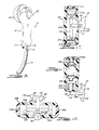
- a fluid driven washing device 10 of the present invention is shown.
- the device 10 has a handle portion 12, a body portion 14, a fluid control lever 16, a soap injection mechanism 17, a dilution control lever 18, a scrubbing member 20, and a spraying member 22.
- a supply conduit 24 is connected between the device 10 and a fluid source 26 for supplying fluid to the device 10, such as a shower pipe 25 ( Figure 1) or faucet pipe 27 ( Figure 2).
- a return conduit 28 is connected to the device 10 for returning the working fluid to a bath tub 29, and into the drain of that bath tub 29.
- a collar member 8 employed with the device 10 as used in Figure 1 is shown enlarged in Figure 13, having an exit port 9 with the supply conduit 24 attached thereto.
- the collar 8 has conventional interior threads to secure the collar 8 onto a conventional shower pipe 25.
- the collar 8 also has an extended threaded portion 11 for threadably securing a conventional shower head 15 to the collar 8.
- a control valve 13 is disposed on the collar 8 for determining the flow of the fluid into the supply conduit 24 or to the conventional shower head 15 ( Figure 1).
- a hook 19 may be positioned on the collar 8 for hanging the washing device 10 via a cooperative element (not shown) on the device 10 or via the base 21 containing the supply conduit 24 and the return conduit 28.
- the device 10 may be attached to the wall via a spring clip 23 ( Figure 1) or similar device.
- the return conduit 28 should also be stabilized by a plurality of clips 25 mounted on the wall.
- the device 10 has a body portion 14 and handle portion 12. Both portions 12 and 14 are enclosed by a housing 30 forming a body cavity 31.
- the housing 30 provides the washing device 10 with a compact, handy, sleek appearance.
- the sprayer member 22 is positioned on the housing 30 opposite the scrubber member 20.
- the sprayer member 22 is comprised of a plate 32 and a sprayer body 34, having an inlet port 36.
- the inlet port 36 is connected to a supply conduit 38 to provide pressurized fluid to the sprayer member 22.
- the sprayer body 34 has an annular groove 40 positioned about its exterior surface between an annular lip 41 and an annular flange 42 for snap fitting the sprayer body 34 into the housing 30.
- the sprayer plate 32 has a plurality of apertures 44 in its circular planar surface for feeding pressurized fluid out of the device 10 and onto the user.
- the sprayer plate 32 has a circumferential flange 46, which, in turn, has an interior groove 48 on the interior surface of the flange 46, for securing the sprayer plate 32 onto the sprayer body 34.
- the sprayer plate 32 is snap fit onto the sprayer body 34 by interlocking the sprayer body flange 42 into the sprayer plate groove 48.
- the hollow interior chamber 43 of the handle portion 12 acts as a passageway for several conduits, including the supply and return conduits 24 and 28 ( Figure 14).
- the handle 12 is canted with respect to the body 14 at an angle of about 15° to 30° to provide the device 10 with appealing kinesthetic effects.
- a manifold and control valve 49 ( Figures 4 and 14) is disposed in the handle for separating the supply conduit 24 into a plurality of supply conduits (38, and 112 or 62) for operating the device.
- the manifold and valve 49 is controlled by the user via control lever 16.
- a dilution mechanism 50 is also positioned on the handle 12.
- the dilution mechanism 50 comprises the lever 18, a chamber 52 having an inlet port 56 and an exit port 58, and an arm 54 having a flexible end element 55 ( Figures 4 and 5).
- the lever 18 is pivotally mounted on the handle 12 by a pivot pin 60 which also pivots the arm 54.
- Supply conduit 62 supplies fluid to the chamber 52 through inlet port 56.
- the fluid pressure of the fluid entering the chamber 52 holds the arm 54 against the exit port 58 ( Figure 5).
- exit port 58 opens enabling the fluid in the chamber 52 to exit into a conduit 64 to a mechanism for placing dilution water onto the scrubber member 20 as will be described below.
- the soap injection mechanism 17 comprises a storage cylinder 66 and a plunger 68.
- the storage cylinder 66 is secured to the housing 30 by a conventional framing mechanism 70 and is filled with liquid soap or a liquid soap mixture.
- the plunger 68 is pushed, the soap or soap mixture exits into a conduit 72 communicating with the scrubbing member 20.
- the amount of soap or soap mixture supplied is determined by the dispostion of the plunger as set by a series of interference stops within the cylinder which positively click as the plunger passes each stop and hold the plunger in a selected position.
- the soap conduit 72 and the dilution conduit 64 intersect and also communicate with the scrubbing member 20 at a dilution manifold 74 ( Figures 4 and 8).
- the dilution manifold 74 comprises a chamber 76, a pair of entrance ports 78 and 79, and an exit port 80.
- the conduits 64 and 72 are secured to the entrance ports 78 by conventional fittings.
- the conduits 64 and 72 provide soap and fluid to the scrubber member 20 via the exit port 80, in communication with the chamber 76, communicating with a passageway 82 which, in turn, feeds into the interior of the scrubbing member 20.
- the dilution manifold 74 supplies the scrubbing member 20 with a soap and dilution fluid in successive steps as discussed in more detail below.
- the scrubbing member 20 comprises a cleaning element 90 and a holding element 92.
- the holding element 92 may be a single part or an assembly integrated by conventional means.
- the cleaning element 90 a sponge in the preferred embodiment, is detachably mounted to the holding element 92 by means of a series of inwardly directed pointed ribs 91 disposed circumferentially around the element 92 ( Figure 8) which engage by press fit an annula lip 93 on the sponge 90.
- the holding element 92 has a pivot shaft 94 extending therefrom.
- the pivot shaft 94 has passageway 82 passing through it and is rotatably secured in the housing 30 at a bearing 95.
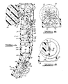
- a pinion gear 96 is disposed on the pivot shaft 94 in the interior body cavity 31 and engages a rack gear 98 positioned on an extended rod 100.
- the rod 100 in communication with a fluid actuator, such as a hydraulic piston assembly 105, drives the rack 98, which, in turn, rotates the pinion gear 96, thus generating reciprocating rotational movement in the scrubbing member 20.
- the rod 100 communicates with a piston member 102 as part of a fluid actuator.
- the piston member 102 is positioned in a cylinder 104 in the body portion 14 of the device 10.
- the hydraulic piston assembly 105 is driven in a receiprocating linear motion.
- the hydraulic piston assembly 105 is controlled by a hydraulic drive assembly 110 ( Figure 6 or 7).
- a supply conduit 112 from the manifold and valve 49 is divided into two conduits 114 and 116 by a T-shaped manifold 115 to supply fluid to the drive assembly 110.
- the drive assembly 110 has a pair of return conduits 118 and 120, commonly joined by a second T-shaped manifold 119. These conduits 118 and 120 feed into the drain conduit 28 to return the working fluid to the drain of the bath tub 29.
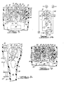
- the drive assembly 110 in accordance with the present invention, as shown in Figures 6 and 7, comprises supply conduits 114 and 116 communicating with chambers 124 and 126, respectively, through ports 128 and 130, gate members 132 and 133 positioned in each chamber 124 and 126, as will be described below, and return conduits 118 and 120 in communication with the chambers 124 and 126, respectively, through ports 134 and 136.
- the assembly 110 also includes port 138 in chamber 124 which communicates with conduit 142, which, in turn, communicates with the piston cylinder 104, and port 148 in communication with chamber 126, which communicates with conduit 152, which also communicates with the piston cylinder 104.
- Conduit 142 is fitted to port 154 at the bottom portion of the piston cylinder 104 and conduit 152 is fitted to port 156 in the upper portion of the piston cylinder 104 ( Figure 4).
- the device 10 operates as follows: With the piston 102 in its "down" position, fluid in conduit 114 passes through chamber 124, through conduit 142, through port 154, into the bottom of the piston cylinder 104, forcing the piston 102 and rod 100 upward ( Figures 4 and 6). While this is occurring, the fluid in the top portion of the piston cylinder 104 is forced by the piston 102 through port 156, into conduit 152, through chamber 126, through conduit 120, and through drain conduit 28 into the bath tub.
- the gate members 132 and 133 are rotatably secured by pins 160 in the chambers 124 and 126, respectively.
- the pins 160 are securely mounted to bar linkages 162 and 163 such that bar linkage 162 and gate member 132 move together and bar linkage 163 and gate member 133 move together.
- the bar linkages 162 and 163 are rotatably mounted to a main bar linkage 164.
- the movement of the main bar linkage 164 provides the gate members 132 and 133 in chambers 124 and 126, respectively, with opening and closing action of the fluid inlet ports 128 and 130, and, respectively, for outlet ports 118 and 120.
- Each of the gate members 132 and 133 each comprise an angulated member having a sealing surface 137 along one side thereof and a securing portion 139 for securing the member 135 to the pins 160 while still allowing rotation.
- the member 132 or 133 is bent at a selected angle for opening and closing the desired ports upon the movement of the bar linkages. In the present embodiment, this angle is approximately 120 degrees.
- the main linkage bar 164 moves within a yoke assembly 170.
- the yoke assembly 170 includes a yoke disc 172, a pivoted rod member 174, and a resilient biasing member 176.
- the yoke disc 172 is rotatably mounted on a flange 178 disposed in the body cavity 31 by a conventional bolt fastener 180.
- the yoke disc 172 has a pair of pins 182 and 184 ( Figures 6 and 7) extending from its rear surface for enchancing movement of the yoke disc 172.
- the yoke disc 172 also has a circumferential slot 173 in which is disposed a pin 196 attached to the main linkage bar 164.
- the rod member 174 is pivotally mounted on a flange 188 ( Figure 4) in the body cavity 31 by a conventional fastener 190 and is also pivotally secured to the yoke disc 172 by a pin 192.
- the rod member 174 has a second linear yoke 194.
- a pin 192 fixedly secured to the yoke disc 172, is positioned within the yoke 194. The positioning of the pin 192 enables the yoke disc 172 to communicate with the rod member 174.
- the resilient biasing member 176 peferably a helical spring, positioned coaxially with and around the rod member 174, is held in place on the rod member 174 at one end by the pin 190 of the rod member 174 and at other end by the pin 192 of the yoke disc 172.
- the rotation of the yoke disc 172 moves the pin 192 along an arcuate path against the spring 176 within the yoke 194 of the rod member 174.
- the pin 196 remains within the slot 173 and the slot 173 moves with the yoke disc 172 without moving the linkage bar pin 196 or the main linkage bar 164 until the rod member 174 passes its vertical position beyond which position the energy stored in the spring 176 is rapidly released.
- the yoke disc 172 is rapidly rotated and the slot 173 forces the pin 196 and the main linkage bar 164 to a new position. In this manner, the ports in the chambers 124 and 126, respectively, are opened and closed, since the bar 164 only travels to one of two positions.
- the yoke disc 172 actuates the switch members 132 and 133 between two to four times per second, producing two to four reciprocating rotational strokes of the scrubbing member per second.
- the switch 132 is in an "open” position uncovering entrance port 128 (as shown in Figure 6).
- the bar 186 will push on pin 182, forcing the yoke disc 172 to rotate in a counterclockwise direction and store energy in the spring 176.
- the spring 176 releases its stored energy. This action rapidly moves the pin 196 and thereby the main linkage bar 164 to its alternate position to reverse the switch member 132 from an "open" to "closed” position on the port 128 and the port 130 in chamber 126 is opened.
- FIGs 10 through 12 illustrate alternate embodiments of the piston assembly 105.
- a diaphragm assembly 210 comprising ports 212 and 214, diagphragms 216 and 218, a piston member 220, and a linkage rod 222 having a bar 223 mounted as shown.
- the fluid successively enters and exits ports 212 and 214, forcing the piston member 220 to reciprocally move in the cylinder 224.
- This reciprocal movement actuates the rod 222 driving rack 98 (via an additional mechanism not shown), which, in turn, produces reciprocating rotatable movement in the scrubbing member 20 while also moving the bar 223 between pins 182 and 184 to move the yoke assembly 170 and control the piston assembly 105.
- a bellows-spring assembly 230 is illustrated in Figure 11.
- the bellows-spring assembly 230 comprises a port 232, a bellows member 234, a piston 236, a rod 238, a bar 240, and a return spring 242.
- the fluid enters port 232 forcing fluid into bellows 234, expanding the bellows 234 to actuate the piston 236.
- the piston 236 moves the rod 238 which, in turn, drives the rack 98 via extended rod 100, producing reciprocating rotatable movement in the scrubbing member 20.
- a gate member such as that indicated by the numeral 132 or 133 (in Figures 6 and 7) reverses to cut off the flow into the piston cylinder. This action opens the return conduit.
- the spring 242 expands, compressing the bellows member 234, forcing the fluid out port 232, returning the rod 238, the rod 100, and bar 240 to their former positions. With this embodiment, only one control chamber with three conduits and one gate member would be needed.
- a horizontally disposed piston assembly 248 is illustrated in Figure 13.
- the assembly 248 comprises a rack 250, a pair of pistons 252 and 253, moving within a cylinder 254, and ports 256 and 258, one at each end of the cylinder 254.
- the rack 250 drives the pinion 96 to drive the scrubbing member 20.
- the fluid successively enters and exits ports 256 and 258, respectively, forcing the rack 250 to drive the scrubbing member 20 in a rotating reciprocal motion.
- the linkage bar 260 rotates the yoke disc 172 as described above to control the piston assembly 105.
Landscapes
- Engineering & Computer Science (AREA)
- Health & Medical Sciences (AREA)
- Public Health (AREA)
- Water Supply & Treatment (AREA)
- Mechanical Engineering (AREA)
- Epidemiology (AREA)
- General Health & Medical Sciences (AREA)
- Cleaning By Liquid Or Steam (AREA)
- Reciprocating Pumps (AREA)
- Nozzles (AREA)
Applications Claiming Priority (2)
| Application Number | Priority Date | Filing Date | Title |
|---|---|---|---|
| US77215185A | 1985-09-03 | 1985-09-03 | |
| US07/004,234 US4703536A (en) | 1985-09-03 | 1987-01-07 | Fluid motor driven washing accessory |
Publications (2)
| Publication Number | Publication Date |
|---|---|
| EP0293522A2 true EP0293522A2 (de) | 1988-12-07 |
| EP0293522A3 EP0293522A3 (de) | 1989-04-05 |
Family
ID=26672777
Family Applications (1)
| Application Number | Title | Priority Date | Filing Date |
|---|---|---|---|
| EP87303973A Withdrawn EP0293522A3 (de) | 1985-09-03 | 1987-05-01 | Mit Flüssigkeit angetriebenes Waschgerät |
Country Status (2)
| Country | Link |
|---|---|
| US (1) | US4703536A (de) |
| EP (1) | EP0293522A3 (de) |
Cited By (2)
| Publication number | Priority date | Publication date | Assignee | Title |
|---|---|---|---|---|
| DE9312806U1 (de) * | 1993-08-26 | 1993-11-11 | Stolz, Robert, 54673 Neuerburg | Körperbürste |
| DE9410730U1 (de) * | 1994-07-05 | 1994-09-01 | Bollen, Fritz Laurenz, 47623 Kevelaer | Rückenwaschbürste |
Families Citing this family (14)
| Publication number | Priority date | Publication date | Assignee | Title |
|---|---|---|---|---|
| GB2219738B (en) * | 1988-06-15 | 1992-02-19 | Peter Henry Underwood | Shower installations |
| JPH0663284U (ja) * | 1993-02-05 | 1994-09-06 | リョービ株式会社 | 動力工具の駆動部構造 |
| USD380069S (en) * | 1995-10-23 | 1997-06-17 | Waxing Corporation Of America, Inc. | Detailing polisher |
| US7377282B2 (en) * | 2002-09-13 | 2008-05-27 | Bear-Ink Corporation | Nail polish removal tool |
| US20040172779A1 (en) * | 2003-03-06 | 2004-09-09 | Sam Zhadanov | Rotatable washing device and attachments provided therefor |
| US20090192422A1 (en) * | 2008-01-29 | 2009-07-30 | Dimension One Spas, Inc. | Handheld Massagers and Methods of Operation |
| US10750849B2 (en) | 2015-04-03 | 2020-08-25 | Water Pik, Inc. | Skin cleansing and massaging system |
| US9643195B2 (en) * | 2015-08-27 | 2017-05-09 | James Streetmaker | Handheld soap dispensing scrubbing shower sprayer |
| USD828694S1 (en) | 2016-04-04 | 2018-09-18 | Water Pik, Inc. | Handheld skin exfoliator |
| US20170290404A1 (en) * | 2016-04-12 | 2017-10-12 | Thao Le | Fingernail Polishing Assembly |
| USD861830S1 (en) | 2017-11-13 | 2019-10-01 | Water Pik, Inc. | Handheld cleansing device |
| USD904039S1 (en) | 2017-11-13 | 2020-12-08 | Water Pik, Inc. | Shower accessory hanger |
| USD854654S1 (en) | 2017-11-13 | 2019-07-23 | Water Pik, Inc. | Bracket for a handheld cleansing device |
| USD898374S1 (en) | 2018-07-02 | 2020-10-13 | Water Pik, Inc. | Skin cleansing brush |
Family Cites Families (9)
| Publication number | Priority date | Publication date | Assignee | Title |
|---|---|---|---|---|
| US2905171A (en) * | 1958-05-13 | 1959-09-22 | Crescenzo Anthony De | Portable vibrating and water therapy device |
| US3283352A (en) * | 1965-06-28 | 1966-11-08 | Jacob Frank | Water powered cleaning device |
| US3443271A (en) * | 1966-05-09 | 1969-05-13 | Henry W Lyons | Reciprocating fluid motor |
| US3932909A (en) * | 1974-10-25 | 1976-01-20 | George Beldon Johnson | Personal self-powered scrub brush |
| DE2702278A1 (de) * | 1977-01-20 | 1978-07-27 | Herbert Geiger | Reinigungs- und massagegeraet |
| US4282623A (en) * | 1979-04-03 | 1981-08-11 | Gacuzana Delancey J | Scrubber apparatus |
| NZ201879A (en) * | 1981-09-14 | 1985-08-16 | Sabco Ltd | Brush;water driven,unbalanced impeller;bristles vibrate |
| US4417826A (en) * | 1981-12-24 | 1983-11-29 | Constantinos Floros | Liquid driven rotary brush with liquid soap feeder |
| US4458676A (en) * | 1982-12-06 | 1984-07-10 | Pileggi Vincent D | Portable spa massager |
-
1987
- 1987-01-07 US US07/004,234 patent/US4703536A/en not_active Expired - Fee Related
- 1987-05-01 EP EP87303973A patent/EP0293522A3/de not_active Withdrawn
Cited By (2)
| Publication number | Priority date | Publication date | Assignee | Title |
|---|---|---|---|---|
| DE9312806U1 (de) * | 1993-08-26 | 1993-11-11 | Stolz, Robert, 54673 Neuerburg | Körperbürste |
| DE9410730U1 (de) * | 1994-07-05 | 1994-09-01 | Bollen, Fritz Laurenz, 47623 Kevelaer | Rückenwaschbürste |
Also Published As
| Publication number | Publication date |
|---|---|
| US4703536A (en) | 1987-11-03 |
| EP0293522A3 (de) | 1989-04-05 |
Similar Documents
| Publication | Publication Date | Title |
|---|---|---|
| US4703536A (en) | Fluid motor driven washing accessory | |
| US4412823A (en) | Oral cavity cleaner | |
| US9346180B2 (en) | Appliance for personal care with automatic fluid dispenser | |
| US5716007A (en) | Battery operated fluid dispenser | |
| US5927290A (en) | Liquid dispensing hair brush | |
| US6210057B1 (en) | Multipurpose applicator | |
| US4175299A (en) | Power toothbrush or the like with orbital brush action | |
| US4498463A (en) | Massage apparatus | |
| JPH0755225B2 (ja) | 洗浄装置 | |
| GB2584359A (en) | Hand-held integral airbrush | |
| CN112483682B (zh) | 流量调节装置 | |
| JP4228244B2 (ja) | シャワー装置及びシャワーブース | |
| JP3165079B2 (ja) | シャワー装置 | |
| US4353141A (en) | Power toothbrush | |
| CN112281992B (zh) | 一种带有加液功能的双管淋浴系统 | |
| CN212382243U (zh) | 自动按摩洗头机 | |
| US3966359A (en) | Apparatus for body hygiene | |
| WO2024082972A1 (en) | Pet paw washing arrangement and hand-wearable paw washing device and washing method thereof | |
| CN110538730A (zh) | 一种新型出水切换结构及花洒 | |
| CN108561597B (zh) | 一种应用于分水器的人性化切换装置 | |
| JPH04346862A (ja) | 手持ち液体ディスペンサ | |
| JP2003268845A (ja) | 衛生洗浄装置 | |
| CN206761649U (zh) | 双储液腔喷液拖把 | |
| CN217285672U (zh) | 一种清洁工具 | |
| WO2005094626A1 (en) | Hair washing device with a scratching unit |
Legal Events
| Date | Code | Title | Description |
|---|---|---|---|
| PUAI | Public reference made under article 153(3) epc to a published international application that has entered the european phase |
Free format text: ORIGINAL CODE: 0009012 |
|
| AK | Designated contracting states |
Kind code of ref document: A2 Designated state(s): AT BE CH DE ES FR GB GR IT LI LU NL SE |
|
| PUAL | Search report despatched |
Free format text: ORIGINAL CODE: 0009013 |
|
| AK | Designated contracting states |
Kind code of ref document: A3 Designated state(s): AT BE CH DE ES FR GB GR IT LI LU NL SE |
|
| STAA | Information on the status of an ep patent application or granted ep patent |
Free format text: STATUS: THE APPLICATION IS DEEMED TO BE WITHDRAWN |
|
| 18D | Application deemed to be withdrawn |
Effective date: 19891006 |