EP0293577A2 - Système d'échappement à silencieux pour moteurs à combustion interne - Google Patents
Système d'échappement à silencieux pour moteurs à combustion interne Download PDFInfo
- Publication number
- EP0293577A2 EP0293577A2 EP88105788A EP88105788A EP0293577A2 EP 0293577 A2 EP0293577 A2 EP 0293577A2 EP 88105788 A EP88105788 A EP 88105788A EP 88105788 A EP88105788 A EP 88105788A EP 0293577 A2 EP0293577 A2 EP 0293577A2
- Authority
- EP
- European Patent Office
- Prior art keywords
- housing
- muffler
- line
- exhaust
- exhaust system
- Prior art date
- Legal status (The legal status is an assumption and is not a legal conclusion. Google has not performed a legal analysis and makes no representation as to the accuracy of the status listed.)
- Granted
Links
Images

Classifications
-
- F—MECHANICAL ENGINEERING; LIGHTING; HEATING; WEAPONS; BLASTING
- F02—COMBUSTION ENGINES; HOT-GAS OR COMBUSTION-PRODUCT ENGINE PLANTS
- F02B—INTERNAL-COMBUSTION PISTON ENGINES; COMBUSTION ENGINES IN GENERAL
- F02B37/00—Engines characterised by provision of pumps driven at least for part of the time by exhaust
- F02B37/12—Control of the pumps
- F02B37/18—Control of the pumps by bypassing exhaust from the inlet to the outlet of turbine or to the atmosphere
-
- F—MECHANICAL ENGINEERING; LIGHTING; HEATING; WEAPONS; BLASTING
- F01—MACHINES OR ENGINES IN GENERAL; ENGINE PLANTS IN GENERAL; STEAM ENGINES
- F01N—GAS-FLOW SILENCERS OR EXHAUST APPARATUS FOR MACHINES OR ENGINES IN GENERAL; GAS-FLOW SILENCERS OR EXHAUST APPARATUS FOR INTERNAL-COMBUSTION ENGINES
- F01N1/00—Silencing apparatus characterised by method of silencing
- F01N1/08—Silencing apparatus characterised by method of silencing by reducing exhaust energy by throttling or whirling
- F01N1/10—Silencing apparatus characterised by method of silencing by reducing exhaust energy by throttling or whirling in combination with sound-absorbing materials
-
- F—MECHANICAL ENGINEERING; LIGHTING; HEATING; WEAPONS; BLASTING
- F01—MACHINES OR ENGINES IN GENERAL; ENGINE PLANTS IN GENERAL; STEAM ENGINES
- F01N—GAS-FLOW SILENCERS OR EXHAUST APPARATUS FOR MACHINES OR ENGINES IN GENERAL; GAS-FLOW SILENCERS OR EXHAUST APPARATUS FOR INTERNAL-COMBUSTION ENGINES
- F01N5/00—Exhaust or silencing apparatus combined or associated with devices profiting by exhaust energy
- F01N5/04—Exhaust or silencing apparatus combined or associated with devices profiting by exhaust energy the devices using kinetic energy
-
- Y—GENERAL TAGGING OF NEW TECHNOLOGICAL DEVELOPMENTS; GENERAL TAGGING OF CROSS-SECTIONAL TECHNOLOGIES SPANNING OVER SEVERAL SECTIONS OF THE IPC; TECHNICAL SUBJECTS COVERED BY FORMER USPC CROSS-REFERENCE ART COLLECTIONS [XRACs] AND DIGESTS
- Y02—TECHNOLOGIES OR APPLICATIONS FOR MITIGATION OR ADAPTATION AGAINST CLIMATE CHANGE
- Y02T—CLIMATE CHANGE MITIGATION TECHNOLOGIES RELATED TO TRANSPORTATION
- Y02T10/00—Road transport of goods or passengers
- Y02T10/10—Internal combustion engine [ICE] based vehicles
- Y02T10/12—Improving ICE efficiencies
Definitions
- the invention relates to an exhaust system with a silencer for a turbocharged reciprocating piston internal combustion engine according to the preamble of claim 1.
- the characterizing features of claim 1 serve to solve this problem. If the exhaust gas of the bypass line is added to the exhaust gas flow in the main line by ejector action, the mixing takes place in the turbulent peripheral area of the free jet generated by the main flow. The turbulence and flow losses can be kept small in this way. The overall efficiency of the internal combustion engine is increased. At the same time, the ejector admixture in the muffler effectively attenuates the exhaust noise.
- the main line is connected to a central pipe fixed in the silencer housing, from which the exhaust gas emerges as a free jet. The bypass flow is blown into an aperture opening surrounding this free jet. In addition, the suction of the free jet acts on it and causes it to mix with the turbulent peripheral zone of the free jet without causing major flow losses.
- the central tube is expanded in a diffuser-like manner; the pitch angle is approx. 4 °.
- the bypass flow is throttled to reduce noise in an annular space surrounding the central tube of the muffler housing and from there to the aperture.
- the sound of the main and bypass flow is damped together in a nozzle tube coaxial with the central tube, which is provided with a large number of radial bores and is surrounded by a damping wool packing.
- a main line 2 for exhaust gas leads from the cylinder head 1 of a reciprocating piston internal combustion engine to the turbine 3 of a turbocharger 4 and from there, after flowing through a silencer 5, into the open.
- Parallel to the turbine 3 is a bypass line 6, which also opens into the silencer 5.
- the bypass flow mixes with the exhaust gas flow from the main line 2.
- a bypass valve 7 is inserted into the bypass line 6, via which, depending on its position, more or less exhaust gas reaches the silencer 5 without impinging the turbine 3.
- the turbine 3 drives a compressor 8, with which fresh air is sucked in via an air filter 9 and conveyed into a charge air line 10 while increasing the pressure.
- the charge air line 10 leads via a charge air cooler 11 to an air quantity meter 12 controlling an injection system and from there to the cylinder head 1 of the internal combustion engine.
- the achievable boost pressure also depends on how high the atmospheric pressure of the fresh air entering the compressor is. Since this supply pressure decreases with increasing geodetic height, the boost pressure would also decrease accordingly.
- the bypass valve is closed more and more with increasing geodetic height at which the internal combustion engine is located.
- the throughput ratio of the bypass line to the main line which is approx. 45% to 55% at sea level, is reduced to 0% to 100% at maximum geodetic height.
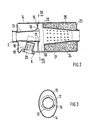
- FIGS. 2 and 3 Structural measures to increase the turbine efficiency and thus the overall efficiency of the internal combustion engine are implemented on the silencer shown in FIGS. 2 and 3.
- the main line 2 coming from the turbine 3 is connected to a central tube 13, which is fastened on the end face to the housing 14 of the silencer 5.
- the central tube 13 is passed through a partition 15 of the housing 14 and held in it with three radially protruding knobs 16. Between the knobs 16 are three passage areas of an aperture 17.
- the end 19 of the bypass line 6 projects into an annular space 18 located between the central tube 13 and the inner wall of the housing 14 and is fastened in the casing of the housing 14.
- the end 19 is closed at the end; on the circumference it is provided with radial bores 20, through which the bypass flow is throttled and soundproofed enters the annular space 18.
- a nozzle tube 21 is fastened coaxially to the central tube in the housing 14 with a collar 22 and is led out of the housing 14 to the outside at the end face 23.
- the nozzle tube 21 has a pattern of equidistant bores 24 on its jacket.
- the space between the nozzle tube and the inner wall of the housing 14 is filled with damping wool 25.
- the exhaust gas emerges from the central tube 13 and entrains the bypass flow flowing from the annular space 18 via the orifice opening 17 by ejector action.
- a mixing of the two exhaust gas flows takes place in the annular mixing space 26 located between the partition and the collar of the nozzle tube 21.
Landscapes
- Engineering & Computer Science (AREA)
- Chemical & Material Sciences (AREA)
- Combustion & Propulsion (AREA)
- Mechanical Engineering (AREA)
- General Engineering & Computer Science (AREA)
- Exhaust Silencers (AREA)
- Supercharger (AREA)
Applications Claiming Priority (2)
| Application Number | Priority Date | Filing Date | Title |
|---|---|---|---|
| DE3718875 | 1987-06-05 | ||
| DE19873718875 DE3718875A1 (de) | 1987-06-05 | 1987-06-05 | Abgasanlage mit schalldaempfer fuer eine brennkraftmaschine |
Publications (3)
| Publication Number | Publication Date |
|---|---|
| EP0293577A2 true EP0293577A2 (fr) | 1988-12-07 |
| EP0293577A3 EP0293577A3 (en) | 1990-08-01 |
| EP0293577B1 EP0293577B1 (fr) | 1992-01-02 |
Family
ID=6329138
Family Applications (1)
| Application Number | Title | Priority Date | Filing Date |
|---|---|---|---|
| EP88105788A Expired - Lifetime EP0293577B1 (fr) | 1987-06-05 | 1988-04-12 | Système d'échappement à silencieux pour moteurs à combustion interne |
Country Status (4)
| Country | Link |
|---|---|
| US (1) | US4807439A (fr) |
| EP (1) | EP0293577B1 (fr) |
| JP (1) | JPS63309708A (fr) |
| DE (2) | DE3718875A1 (fr) |
Families Citing this family (15)
| Publication number | Priority date | Publication date | Assignee | Title |
|---|---|---|---|---|
| US5255481A (en) | 1990-09-04 | 1993-10-26 | Ppg Industries, Inc. | Spacer and spacer frame for an insulating glazing unit and method of making same |
| US5177916A (en) * | 1990-09-04 | 1993-01-12 | Ppg Industries, Inc. | Spacer and spacer frame for an insulating glazing unit and method of making same |
| CA2125504C (fr) | 1990-09-04 | 1996-12-10 | Robert B. Hodek | Entretoise de faible conductivite thermique pour vitrage isolant et mode de fabrication connexe |
| US5675944A (en) * | 1990-09-04 | 1997-10-14 | P.P.G. Industries, Inc. | Low thermal conducting spacer assembly for an insulating glazing unit and method of making same |
| US5761946A (en) * | 1992-06-30 | 1998-06-09 | Ppg Industries, Inc. | Method of making spacer stock |
| US5916136A (en) * | 1997-10-02 | 1999-06-29 | Ettere; Mark | Aspiration device for vehicle engine exhaust system |
| US6202413B1 (en) | 1999-02-04 | 2001-03-20 | Cummins Engine Company, Inc. | Multiple nozzle ejector for wastegated turbomachinery |
| US6688425B2 (en) * | 2001-10-09 | 2004-02-10 | Siemens Vdo Automotive, Inc. | Induction system with low pass filter for turbo charger applications |
| US7017706B2 (en) * | 2001-12-21 | 2006-03-28 | Honeywell International, Inc. | Turbine noise absorber |
| RU2301899C1 (ru) * | 2006-01-10 | 2007-06-27 | Общество с ограниченной ответственностью "Федеральный учебный межвузовский научный производственный центр" | Способ и устройство управления газообменом в дизеле с газотурбинным наддувом |
| US20090139164A1 (en) * | 2007-12-04 | 2009-06-04 | Intigral, Inc. | Insulating glass unit |
| US20090139165A1 (en) * | 2007-12-04 | 2009-06-04 | Intigral, Inc. | Insulating glass unit |
| US20090139163A1 (en) * | 2007-12-04 | 2009-06-04 | Intigral, Inc. | Insulating glass unit |
| RU2704659C2 (ru) * | 2017-07-26 | 2019-10-30 | Общество с ограниченной ответственностью "УралГазРемонт" | Способ охлаждения вала трансмиссии газотурбинного привода и элементов КИП и устройство для его осуществления |
| CA3298986A1 (en) * | 2020-01-13 | 2026-03-02 | Polaris Industries Inc. | Turbocharger lubrication system for a two-stroke engine |
Family Cites Families (7)
| Publication number | Priority date | Publication date | Assignee | Title |
|---|---|---|---|---|
| GB896584A (en) * | 1957-09-11 | 1962-05-16 | Garrett Corp | Control apparatus for internal combustion engine turbosuperchargers |
| JPS5188405A (ja) * | 1975-02-01 | 1976-08-03 | Korogasushorisochi | |
| FR2338382A1 (fr) * | 1976-01-19 | 1977-08-12 | Inst Francais Du Petrole | Dispositif perfectionne de suralimentation des moteurs a combustion interne |
| DE2913488A1 (de) * | 1979-04-04 | 1980-10-09 | Porsche Ag | Vorrichtung zur regelung des ladedruckes bei einer mit abgasaufladung betriebenen brennkraftmaschine |
| FR2496758A4 (fr) * | 1979-04-04 | 1982-06-25 | Porsche Ag | Dispositif de regulation de la pression d'admission d'un moteur a combustion interne suralimente par les gaz d'echappement |
| DE3048933A1 (de) * | 1980-12-24 | 1982-07-15 | Dr.Ing.H.C. F. Porsche Ag, 7000 Stuttgart | Vorrichtung zur regelung des ladedruckes bei einer mit abgasaufladung betriebenen brennkraftmaschine |
| US4463564A (en) * | 1981-10-23 | 1984-08-07 | The Garrett Corporation | Turbocharger turbine housing assembly |
-
1987
- 1987-06-05 DE DE19873718875 patent/DE3718875A1/de not_active Withdrawn
-
1988
- 1988-04-12 DE DE8888105788T patent/DE3867318D1/de not_active Expired - Lifetime
- 1988-04-12 EP EP88105788A patent/EP0293577B1/fr not_active Expired - Lifetime
- 1988-06-03 JP JP63135733A patent/JPS63309708A/ja active Pending
- 1988-06-03 US US07/201,930 patent/US4807439A/en not_active Expired - Fee Related
Also Published As
| Publication number | Publication date |
|---|---|
| DE3718875A1 (de) | 1988-12-22 |
| DE3867318D1 (de) | 1992-02-13 |
| JPS63309708A (ja) | 1988-12-16 |
| EP0293577A3 (en) | 1990-08-01 |
| US4807439A (en) | 1989-02-28 |
| EP0293577B1 (fr) | 1992-01-02 |
Similar Documents
| Publication | Publication Date | Title |
|---|---|---|
| EP0293577B1 (fr) | Système d'échappement à silencieux pour moteurs à combustion interne | |
| DE4319380C2 (de) | Brennkraftmaschine mit einem Abgasturbolader | |
| DE10116643C2 (de) | Hubkolbenbrennkraftmaschine | |
| DE2500496A1 (de) | Kompressorvorrichtung | |
| DE3302224C2 (fr) | ||
| DE3034271A1 (de) | Turbinengehaeuse fuer turbolader | |
| DE10260778A1 (de) | Abgasturbolader für eine Brennkraftmaschine | |
| DE102005046507A1 (de) | Brennkraftmaschine mit zwei hintereinander geschalteten Abgasturboladern | |
| EP1881173B1 (fr) | Diffuseur pour un moteur à combustion interne et moteur à combustion interne avec diffuseur | |
| DE3735736A1 (de) | Vorrichtung zum steuern einer turboladeranlage | |
| DE3121341C2 (de) | Abgasleitungssystem zwischen einer nach dem Stauprinzip aufgeladenen, mehrzylindrigen Brennkraftmaschine und einem Abgasturbolader | |
| DE2243269C2 (de) | Luftzuführungssystem, insbesondere Ansaugleitungssystem | |
| DE102009024568A1 (de) | Verdichterlaufrad | |
| DE102005019937B3 (de) | Turbine mit einem Turbinenrad für einen Abgasturbolader einer Brennkraftmaschine und Abgasturbolader für eine Brennkraftmaschine | |
| DE3203558A1 (de) | Kraftstoffeinspritzvorrichtung mit nebenluftsystem | |
| DE102015208906A1 (de) | Saugstrahlpumpe mit variabler Düsengeometrie und Kurbelgehäuseentlüftungseinrichtung | |
| DE102016003742A1 (de) | Abgasnachbehandlungssystem, Brennkraftmaschine und Verfahren zum Betreiben derselben | |
| DE2452219A1 (de) | Abgaslader fuer eine kolbenbetriebene brennkraftmaschine | |
| DE102016113389A1 (de) | Mischvorrichtung für ein Abgasnachbehandlungssystem, Abgasnachbehandlungssystem und Brennkraftmaschine | |
| DE102012008990A1 (de) | System zur Sekundärlufteinblasung für eine Brennkraftmaschine | |
| DE808304C (de) | Zweitaktmotor | |
| DE2021663C3 (de) | Nachverbrennungsanlage für die Abgase von mit einem Abgasturbolader versehenen Kolbenbrennkraftmaschinen | |
| DE3312259C2 (de) | Spiralgehäuse für das radial beaufschlagte Turbinenlaufrad eines Abgasturboladers | |
| DE969105C (de) | Vor dem Ansaugventil oder den Ansaugschlitzen von intermittierend arbeitenden Brennkraftmaschinen angeordnetes Rohrsystem | |
| DE2519281C3 (de) | Einrichtung zur Hoch-Aufladung von Kolben-Brennkraftmaschinen |
Legal Events
| Date | Code | Title | Description |
|---|---|---|---|
| PUAI | Public reference made under article 153(3) epc to a published international application that has entered the european phase |
Free format text: ORIGINAL CODE: 0009012 |
|
| AK | Designated contracting states |
Kind code of ref document: A2 Designated state(s): DE FR GB IT SE |
|
| PUAL | Search report despatched |
Free format text: ORIGINAL CODE: 0009013 |
|
| AK | Designated contracting states |
Kind code of ref document: A3 Designated state(s): DE FR GB IT SE |
|
| 17P | Request for examination filed |
Effective date: 19901210 |
|
| 17Q | First examination report despatched |
Effective date: 19910503 |
|
| ITF | It: translation for a ep patent filed | ||
| GRAA | (expected) grant |
Free format text: ORIGINAL CODE: 0009210 |
|
| AK | Designated contracting states |
Kind code of ref document: B1 Designated state(s): DE FR GB IT SE |
|
| GBT | Gb: translation of ep patent filed (gb section 77(6)(a)/1977) | ||
| REF | Corresponds to: |
Ref document number: 3867318 Country of ref document: DE Date of ref document: 19920213 |
|
| PGFP | Annual fee paid to national office [announced via postgrant information from national office to epo] |
Ref country code: SE Payment date: 19920325 Year of fee payment: 5 |
|
| PGFP | Annual fee paid to national office [announced via postgrant information from national office to epo] |
Ref country code: DE Payment date: 19920331 Year of fee payment: 5 |
|
| PGFP | Annual fee paid to national office [announced via postgrant information from national office to epo] |
Ref country code: GB Payment date: 19920402 Year of fee payment: 5 |
|
| PGFP | Annual fee paid to national office [announced via postgrant information from national office to epo] |
Ref country code: FR Payment date: 19920430 Year of fee payment: 5 |
|
| ET | Fr: translation filed | ||
| PLBE | No opposition filed within time limit |
Free format text: ORIGINAL CODE: 0009261 |
|
| STAA | Information on the status of an ep patent application or granted ep patent |
Free format text: STATUS: NO OPPOSITION FILED WITHIN TIME LIMIT |
|
| 26N | No opposition filed | ||
| PG25 | Lapsed in a contracting state [announced via postgrant information from national office to epo] |
Ref country code: GB Effective date: 19930412 |
|
| PG25 | Lapsed in a contracting state [announced via postgrant information from national office to epo] |
Ref country code: SE Effective date: 19930413 |
|
| GBPC | Gb: european patent ceased through non-payment of renewal fee |
Effective date: 19930412 |
|
| PG25 | Lapsed in a contracting state [announced via postgrant information from national office to epo] |
Ref country code: FR Effective date: 19931229 |
|
| PG25 | Lapsed in a contracting state [announced via postgrant information from national office to epo] |
Ref country code: DE Effective date: 19940101 |
|
| REG | Reference to a national code |
Ref country code: FR Ref legal event code: ST |
|
| EUG | Se: european patent has lapsed |
Ref document number: 88105788.9 Effective date: 19931110 |
|
| PG25 | Lapsed in a contracting state [announced via postgrant information from national office to epo] |
Ref country code: IT Free format text: LAPSE BECAUSE OF NON-PAYMENT OF DUE FEES;WARNING: LAPSES OF ITALIAN PATENTS WITH EFFECTIVE DATE BEFORE 2007 MAY HAVE OCCURRED AT ANY TIME BEFORE 2007. THE CORRECT EFFECTIVE DATE MAY BE DIFFERENT FROM THE ONE RECORDED. Effective date: 20050412 |