EP0293676A1 - Segmentförmige Wanne - Google Patents
Segmentförmige Wanne Download PDFInfo
- Publication number
- EP0293676A1 EP0293676A1 EP88107999A EP88107999A EP0293676A1 EP 0293676 A1 EP0293676 A1 EP 0293676A1 EP 88107999 A EP88107999 A EP 88107999A EP 88107999 A EP88107999 A EP 88107999A EP 0293676 A1 EP0293676 A1 EP 0293676A1
- Authority
- EP
- European Patent Office
- Prior art keywords
- tub
- plastic body
- basin
- moulding
- recesses
- Prior art date
- Legal status (The legal status is an assumption and is not a legal conclusion. Google has not performed a legal analysis and makes no representation as to the accuracy of the status listed.)
- Granted
Links
Images
Classifications
-
- A—HUMAN NECESSITIES
- A47—FURNITURE; DOMESTIC ARTICLES OR APPLIANCES; COFFEE MILLS; SPICE MILLS; SUCTION CLEANERS IN GENERAL
- A47K—SANITARY EQUIPMENT; ACCESSORIES THEREFOR, e.g. TOILET ACCESSORIES
- A47K3/00—Baths; Showers; Appurtenances therefor
- A47K3/28—Showers or bathing douches
- A47K3/40—Pans or trays
-
- A—HUMAN NECESSITIES
- A47—FURNITURE; DOMESTIC ARTICLES OR APPLIANCES; COFFEE MILLS; SPICE MILLS; SUCTION CLEANERS IN GENERAL
- A47K—SANITARY EQUIPMENT; ACCESSORIES THEREFOR, e.g. TOILET ACCESSORIES
- A47K3/00—Baths; Showers; Appurtenances therefor
- A47K3/16—Devices for fastening baths to floors or walls; Adjustable bath feet ; Lining panels or attachments therefor
Definitions
- the invention relates to a segment-shaped trough according to the preamble of claim 1.
- a segment-shaped trough of the type mentioned is already known.
- a tub is described in EP-A2-0 197 183, which is provided with an enamelled sheet metal cladding which extends to the floor and which can be fastened to retaining feet of the tub by means of latching elements, without screws or tools.
- enamelled sheet metal claddings cannot be used everywhere for optical reasons.
- the bathtub which is usually arranged in a corner of a bathroom.
- Underpinning or supports made of polystyrene or polyurethane foam are usually used as holding elements for the tub and tiles.
- the inevitably rigid, unchangeable height dimension is disadvantageous because unevenness in the floor cannot be compensated for.
- the tub legs that are at right angles to each other must be embedded in the wall, which causes a special effort.
- Foamed beams are not free from their own movements, especially due to thermal expansion and shrinkage. The resulting instability can result in the tearing off of tiles and overstressing the sealing joints.
- a segment-shaped trough is known from a patent application. It essentially comprises at least one curved wall part and four feet which can be adjusted in height by means of screw spindles, preferably provided with angle irons, which support the bath rim; Brackets for at least one molded part which is curved to the wall part contour of the tub and extends to the floor and consists of sheet metal and an adhesive layer, which has parallel beads with embossed grooves, which is further provided by means of screw and / or locking elements on the recesses or projections Brackets for hanging the molded part is detachably attached and which itself or in connection with an intermediate body serves as a carrier for cladding elements which can be non-positively, positively or cohesively attached, the molded part being a composite body, on the outside of which the intermediate body can be fastened; the intermediate body has a layer of curable material to which the covering elements (F) can be attached or attached in an adhesive manner; the molded part has recesses which are positively penetrated by the projections of the
- cladding elements can be quickly and precisely attached to the intermediate body provided with a layer of hardenable material and not made of sheet metal.
- This segment-like tub can also be removed easily and without damage.
- the feet provided with angle iron and the molded part reaching down to the floor significantly increase the high level of stability and resilience.
- the structure of the tub shows, however, that these advantages can only be achieved with many, relatively structurally complex and therefore expensive measures.
- the intricately designed molded part is made of sheet metal with an adhesive layer attached to it and has, in terms of production, expensive, parallel, corrugated beads.
- the feet supporting the segment-shaped trough alone are free of angle iron in the area of the screw spindle and are therefore structurally simpler in construction.
- the screw end of the screw can be easily welded to one side on a curved angle iron, while the other side can be locked with a nose of a clamping part so that this part of the foot is held firmly in position and the high adjustable feet provide a high level of stability and Resilience of the tub results.
- the plastic body serving as a molded part is divided in the middle and has two semicircular recesses on the relevant sides thereof, the parts of the plastic body can easily be attached to the middle foot or removed again if necessary.
- Another advantage is that a layer made of a composite material can be easily applied to the outside of the plastic body, to which the cladding elements (F), for example tiles, can be attached without spacing elements for individual adaptation to different tile thicknesses or to the mortar process used and that a removable closure in the area of the tub drain is not required. Since the plastic body has a bore on the inside in a straight design, it can easily be attached to the relevant corner foot of the segment-shaped trough. According to one embodiment of the invention, it is also advantageous that the plastic body can be separated along shortening marks so that part of it can be used for a further tub.
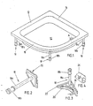
- Fig. 1 shows an oblique view of a segment-shaped trough 10 without substructure, which has straight wall parts 12 and 14 and a curved wall part 16 and rests on feet 18, which are adjustable in height by means of screw spindles 18a to compensate for uneven floors.
- a drain A in the tub 10 is shown on the right side thereof.
- FIG. 2 shows an enlarged oblique view of one of the feet 18 shown in FIG. 1 with the screw spindle 18a, which is firmly connected to a plate-shaped support device 20, for example by welding, and with a screw spindle head 18b with which the screw spindle 18a is adjustable .
- the foot 18 formed in this way can, according to FIG. 3, be firmly locked on a tub rim 22 from below in a simple manner with the aid of a nose 24a of a clamping part 24 3, which can also be driven in laterally with a hammer, for example.
- This stable foot structure as well as modifications thereof alone carry the segment-shaped trough 10 and in this way ensures that the trough 10 is highly stable and resilient.
- FIG. 4 shows in an enlarged oblique view the clamping wedge 24 which can be driven in laterally on the tub edge 22 of the tub 10 by means of a hammer and with which the support device 22 can be locked firmly on the tub edge 22.
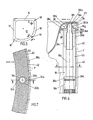
- FIG. 5 shows a top view of the trough 10 shown in FIG. 1 with the same components and a section line A-B drawn through the center of the curved wall part 16.
- the molded part 30 consists of a polystyrene plastic body 30 which does not have to bear the weight and loads of the tub 10, but only for receiving clothing elements F. , for example of tiles.
- the plastic body 30 is divided in the middle according to FIG. 7 and has two semicircular recesses 32a and 32b in its opposite sides 34a and 34b for supporting the screw spindle 18a of the foot 18.
- the semicircular recesses 32a, 32b merge into also semicircular cutouts 36a, 36b with a larger diameter in order to receive a screw spindle head 18b of the foot 18.
- the self-supporting feet 18 for the segment-shaped tub 10 are to compensate for uneven floors with the help of height-adjustable in the semicircular cutouts 36a, 36b of the spindle head 18b within certain limits.
- the plastic bodies 30 reach down to the floor and have a joint 38a that can be sprayed out in a permanently elastic manner at the end to the bent tub edge 22.
- Semicircular recesses 36c, 36d for receiving the screw spindle 18a are also provided in the upper parts of the plastic body 30 in order to enable the foot 18 to be inserted easily into the divided plastic body 30.
- FIG. 6 also shows, a screw spindle cone 18c and a screw spindle end attachment 18d with a beveled end face 18e, which abuts a lower side of a leg 26a of an angle iron 26, are arranged on the screw spindle 18a, with a right-angled bend on one side 18f of the screw spindle extension 18d
- Leg 26b of the angle iron 26 is welded and the leg 26a of the angle iron 26 engages under the tub rim 22 with its upper side.
- Another leg 26c of the angle iron 26 rests on an angle iron 28 welded to the tub 10, so that the tub 10 is supported by the angle irons 26 and 28 and can be firmly locked with the nose 24a of the clamping part 24.
- the plastic body 30 has a layer 42 made of a composite material on an outer side 40, to which the cladding elements F, for example tiles, can be adhesively attached.
- the composite material consists of a hardenable material, for example an adhesive or mortar.
- the cladding elements F are mutually spaced apart by means of sprayable joints 38b (FIG. 7).
- FIG. 7 shows in a sectional view along the line C-D in FIG. 6 the semicircular recesses 32a, 32b which are arranged in mutually opposite sides 34a, 34b of the parts of the plastic body 30.
- the recesses 32a, 32b encompass the screw spindle 18a in this area.
- the screw spindle head 18b is also surrounded by the cutouts 36a and 36b, so that in this way a wall extending from the tub edge 22 to the floor is formed below the curved wall part 16 of the tub 10, on the outside 40 of which a layer 32 made of a composite material, consisting for example of an adhesive or mortar, and cladding elements F, for example Tiles that are attachable. Between the individual cladding elements F, joints 38b which can be sprayed out in a permanently elastic manner are provided.
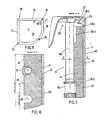
- Fig. 8 shows a plan view of the tub 10 shown in Fig. 1 with an oblique section line A-B.
- FIG. 9 shows an enlarged sectional view along the line A-B in FIG. 8.
- the support device 20 attached to the end of the screw spindle 18a of the foot 18 supports the tub rim 22 in a supportive manner. As already explained, the support device 20 can be firmly locked by the nose 24a of the clamping wedge 24.
- the plastic body 30 has 44 holes 46 on the inside into which the screw spindle 18a or, in not shown milled portions 36a, 36b, the screw spindle head 18b of the foot 18 can be inserted easily and quickly from the inside 44.
- the plastic body 30 can be separated along shortening marks 48 for the use of smaller tubs.
Landscapes
- Health & Medical Sciences (AREA)
- Public Health (AREA)
- Epidemiology (AREA)
- General Health & Medical Sciences (AREA)
- Floor Finish (AREA)
- Sewage (AREA)
- Polishing Bodies And Polishing Tools (AREA)
- Superconductors And Manufacturing Methods Therefor (AREA)
- Iron Core Of Rotating Electric Machines (AREA)
Abstract
Description
- Die Erfindung betrifft eine segmentförmige Wanne gemäß dem Oberbegriff des Anspruchs 1.
- Eine segmentförmige Wanne der eingangs genannten Art ist bereits bekannt. So ist in der EP-A2-0 197 183 eine Wanne beschrieben, die mit einer bis zum Boden reichenden, emaillierten Blechverkleidung versehen ist, welche mittels Rastelementen an Haltefüßen der Wanne befestigt werden kann, und zwar ohne Schrauben oder Werkzeug. Nicht überall sind jedoch solche vorzugsweise emaillierten Blechverkleidungen aus optischen Gründen verwendbar.
- Bekannt ist es auch, die meist in einem Eck eines Baderaumes angeordnete Wanne einzufließen. Als Haltelement für die Wanne und Fliessen werden üblicherweise Untermauerungen oder Träger aus Polystyroloder Polyurethan-Schaum verwendet.
- Hierbei ist das zwangsläufig starr gegebene, nicht veränderliche Höhenmaß nachteilig, denn Bodenunebenheiten können nicht ausgeglichen werden. Aus statischen Gründen müssen bei einer Untermauerung die rechtwinklig zueinander stehenden Wannenschenkel in die Wand eingelassen werden, was einen besonderen Aufwand verursacht. Geschäumte Träger sind nicht frei von Eigenbewegungen, vor allem durch thermische Ausdehnung und Schrumpfung. Die davon herrührende Instabilität kann das Abreißen von Fliesen und eine Überbeanspruchung der Dichtfugen zur Folge haben.
- Ferner ist aus einer Patentanmeldung eine segmentförmige Wanne bekannt. Sie umfaßt im wesentlichen mindestens ein gebogenes Wandteil und vier durch Schraubspindeln höhenverstellbare, bevorzugt mit Winkeleisen versehene Füße, die den Wannenrand stützend untergreifen; Halterungen für wenigstens ein der Wandteil-Kontur der Wanne entsprechend gebogenes, bis zum Boden reichendes, aus Blech und einer Haftschicht bestehendes Formteil, welches bodenparallele Sicken mit eingeprägten Rillen aufweist, welches ferner mittels Schraub- und/oder Rastelementen an den mit Ausnehmungen oder Vorsprüngen versehenen Halterungen zum Einhängen des Formteils lösbar angebracht ist sowie welches selbst oder in Verbindung mit einem Zwischenkörper als Träger für daran kraft-, form- oder stoffschlüssig befestigbare Verkleidungselemente dient, wobei das Formteil ein Verbundkörper ist, an dessen Außenseite der Zwischenkörper befestigbar ist; der Zwischenkörper eine Schicht aus härtbarem Material aufweist, an dem die Verkleidungselemente (F) haftend anbringbar bzw. angebracht sind; das Formteil Ausnehmungen aufweist, die von den Vorsprüngen des Zwischenkörpers formschlüssig durchsetzt sind; zwischen dem Formteil und seinen Halterungen sowohl eine Langlochbefestigung als auch Distanzstücke angeordnet sind; und einen im Bereich des gebogenen Wandteils vorgesehenen abnehmbaren Verschluß, der an einer Inspektionsöffnung nahe einem Ablauf (A) der Wanne angebracht ist.
- Mit dieser Wanne sind zwar eine Reihe von Verbesserungen zum bekannten Stand der Technik geschaffen worden, so können beispielsweise Verkleidungselemente (F) rasch und genau an dem mit einer Schicht aus härtbarem Material versehenen,nicht aus Blech bestehenden Zwischenkörper angebracht werden. Auch kann diese segmentartige Wanne bequem und beschädigungsfrei demontiert werden. Ferner erhöhen die mit Winkeleisen versehenen Füße und das bis auf den Boden reichende Formteil die hohe Standfestigkeit und Belastbarkeit in erheblichem Maße. Der Aufbau der Wanne zeigt aber, daß diese Vorteile nur mit vielen, relativ konstruktiv aufwendigen und daher teuren Maßnahmen erreicht werden. So besteht das kompliziert gestaltete Formteil aus Blech mit einer darauf angebrachten Haftschicht und hat fertigungsmäßig teure bodenparallele, mit Rillen versehene Sicken. Auch die Ausnehmungen im Formteil, in die die Vorsprünge des Zwischenkörpers eingreifen, verteuern diese segmentförmige Wanne. Dies trifft beispielsweise auch für die Schraub- und/oder Rastelemente zu, die durch Distanzstücke zu den an den Füßen angebrachten Winkeleisen auf Abstand gehalten werden. Der am Formteil vorgesehene abnehmbare Verschluß ist zwar zum Abdecken einer Inspektionsöffnung durchaus zweckdienlich, verteuert aber insoweit auch den Gesamtaufbau dieser segmentförmigen Wanne.
- Der Erfindung liegt daher die Aufgabe zugrunde, eine segmentförmige Wanne der eingangs genannten Art vorzuschlagen, deren Aufbau unter dem gebogenen Wandteil konstruktiv erheblich vereinfacht und damit kostengünstiger herstellbar sein soll. Formteile der Wanne sollen dabei so gestaltet sein, daß an ihnen leicht und schnell Verkleidungselemente anbringbar sind. Der Aufbau unter dem gebogenen Teil der segmentförmigen Wanne soll ferner im Bedarfsfall bequem und beschädigungsfrei sowie leicht und schnell demontierbar sein, um guten Zugang zu der unterhalb der Wanne befindlichen Installation zu gewährleisten und sowohl eine hohe Standsicherheit als auch Belastbarkeit zu haben.
- Diese Aufgabe wird mit den Merkmalen des kennzeichnenden Teils des Anspruchs 1 gelöst.
- Weitere Ausgestaltungen der Erfindung ergeben sich aus den Unteransprüchen 2 bis 14.
- Die mit der Erfindung erzielten Vorteile bestehen insbesondere darin, daß die die segmentförmige Wanne allein tragenden Füße im Bereich der Schraubspindel frei von Winkeleisen sind und damit konstruktiv einfacher im Aufbau sind. Der Schraubspindelendansatz der Schraubspindel kann mit einer Seite an einem gebogenen Winkeleisen leicht angeschweißt werden, während die andere Seite mit einer Nase eines Klemmteils so verriegelbar ist, daß dieses Teil des Fußes fest in Position gehalten wird und sich insgesamt mit den höhenverstellbaren Füßen eine hohe Standfestigkeit und Belastbarkeit der Wanne ergibt. Dadurch, daß der als Formteil dienende Kunststoffkörper mittig geteilt und zwei halbkreisförmige Ausnehmungen an den betreffenden Seiten davon aufweist, können die Teile des Kunststoffkörpers leicht an den mittleren Fuß angesetzt bzw. im Bedarfsfall wieder abgenommen werden. Ein weiterer Vorteil liegt ferner darin, daß auf die Außenseite des Kunststoffkörpers eine aus einem Verbundwerkstoff bestehende Schicht leicht auftragbar ist, an der die Verkleidungselemente (F), z.B. Fliesen, ohne Distanzelemente zur individuellen Anpassung an unterschiedliche Fliesendicke bzw. an das benutzte Mörtelverfahren, haftend anbringbar sind und daß ein abnehmbarer Verschluß im Bereich des Wannenablaufes nicht erforderlich ist. Da der Kunststoffkörper bei gerader Ausbildung an der Innenseite eine Bohrung aufweist, kann er leicht an den betreffenden Eckfuß der segmentförmigen Wanne angesetzt werden. Vorteilhaft gemäß einer Ausführungsform der Erfindung ist es auch, daß der Kunftstoffkörper längs Kürzungsmarkierungen trennbar ist, so daß ein Teil davon für eine weitere Wanne verwendet werden kann.
- Ausführungsbeispiele der Erfindung sind in der Zeichnung dargestellt und werden im folgenden näher beschrieben. Es zeigen
- Fig. 1 eine Schrägansicht einer segmentförmigen Wanne mit Füßen;
- Fig. 2 eine vergrößerte Schrägansicht von einem der in Fig. 1 dargestellten Füße;
- Fig. 3 eine Schrägansicht einer Ecke der Wanne mit Fuß;
- Fig. 4 eine vergrößerte Schrägansicht eines Klemmkeils;
- Fig. 5 eine Draufsicht auf die in Fig. 1 darbestellte Wanne mit Schnittlinie A-B;
- Fig. 6 eine vergrößerte Schnittansicht entsprechend der Linie A-B in Fig. 5;
- Fig. 7 eine Schnittansicht entsprechend der Linie C-D in Fig. 6;
- Fig. 8 eine Draufsicht auf die in Fig. 1 dargestellte segmentförmige Wanne mit schräger Schnittlinie A-B;
- Fig. 9 eine vergrößerte Schnittansicht entsprechend der schrägen Linie A-B in Fig. 8 und
- Fig.10 eine Schnittansicht entsprechend der Linie C-D in Fig. 9
- Fig. 1 zeigt in einer Schrägansicht eine segmentförmige Wanne 10 ohne Unterbau, die gerade Wandteile 12 und 14 sowie ein gebogenes Wandteil 16 hat und auf Füßen 18 ruht, die mittels Schraubspindeln 18a zum Ausgleichen von Bodenunebenheiten in bestimmten Grenzen höhenverstellbar sind. Ein Ablauf A in der Wanne 10 ist auf der rechten Seite davon gezeigt.
- Fig. 2 zeigt in einer vergrößerten Schrägansicht einen der in Fig. 1 dargestellten Füße 18 mit der Schraubspindel 18a, die mit einer plattenförmigen Abstützeinrichtung 20, beispielsweise durch Verschweißen, fest verbunden ist, und mit einem Schraubspindelkopf 18b, mit dem die Schraubspindel 18a verstellbar ist.
- Der so ausgebildete Fuß 18 kann gemäß Fig. 3 an einem Wannenrand 22 von unten in einfacher Weise mit Hilfe einer Nase 24a eines Klemmteils 24 fest verriegelt werden, die, wie die Fig. 3 auch zeigt, beispielsweise mit einem Hammer seitlich eingetrieben werden kann. Dieser stabile Fußaufbau wie auch Abwandlungen davon allein tragen die segmentförmige Wanne 10 und gewährleistet auf diese Weise eine hohe Standfestigkeit und Belastbarkeit der Wanne 10.
- Fig. 4 zeigt in einer vergrößerten Schrägansicht den seitlich am Wannenrand 22 der Wanne 10 mittels eines Hammers eintreibbaren Klemmkeil 24, mit dem die Abstützeinrichtung 22 fest am Wannenrand 22 verriegelbar ist.
- Fig. 5 zeigt eine Draufsicht auf die in Fig. 1 dargestellte Wanne 10 mit den gleichen Bauteilen und einer eingezeichneten Schnittlinie A-B durch die Mitte des gebogenen Wandteils 16.
- Fig. 6 zeigt eine vergrößerte Schnittansicht entsprechend der Linie A-B in Fig. 5. Erfindungsgemäß besteht das Formteil 30 aus einem aus Polystyrol hergestellten Kunststoffkörper 30, der nicht das Gewicht und die Belastungen der Wanne 10 zu tragen hat, sondern nur zur Aufnahme von Bekleidungselementen F, z.B. von Fliesen, dient. Der Kunststoffkörper 30 ist gemäß Fig. 7 mittig geteilt und weist zwei halbkreisförmige Ausnehmungen 32a und 32b in seinen einander gegenüberliegenden Seiten 34a und 34b zum Abstützen der Schraubspindel 18a des Fußes 18 auf. Bodenseitig gehen die halbkreisförmigen Ausnehmungen 32a, 32b in gleichfalls halbkreisförmig ausgebildete Ausfräsungen 36a, 36b mit größerem Durchmesser über, um einen Schraubspindelkopf 18b des Fußes 18 aufzunehmen. Die selbsttragenden Füße 18 für die segmentförmige Wanne 10 sind zum Ausgleich von Bodenunebenheiten mit Hilfe des in den halbkreisförmigen Ausfräsungen 36a, 36b untergebrachten Spindelkopfes 18b in bestimmten Grenzen höhenverstellbar.
- Die Kunststoffkörper 30 reichen bis auf den Boden und weisen stirnseitig zum abgebogenen Wannenrand 22 eine dauerelastisch ausspritzbare Fuge 38a auf. Wannenseitig sind in oberen Teilen der Kunststoffkörper 30 ebenfalls halbkreisförmige Aussparungen 36c, 36d zur Aufnahme der Schraubenspindel 18a vorgesehen, um ein leichtes Einsetzen des Fußes 18 in die geteilten Kunststoffkörper 30 zu ermöglichen.
- Wie die Fig. 6 ferner zeigt, sind an der Schraubspindel 18a ein Schraubenspindelkonus 18c und daran ein Schraubspindelendansatz 18d mit abgeschrägter Stirnfläche 18e, die einer Unterseite eines Schenkels 26a eines Winkeleisens 26 anliegt, angeordnet, wobei an einer Seite 18f des Schraubspindelendansatzes 18d ein rechtwinklig abgebogener Schenkel 26b des Winkeleisens 26 angeschweißt ist und der Schenkel 26a des Winkeleisens 26 mit seiner Oberseite den Wannenrand 22 anliegend untergreift. Ein weiterer Schenkel 26c des Winkeleisens 26 liegt einem an der Wanne 10 angeschweißten Winkeleisen 28 auf, so daß damit die Wanne 10 von den Winkeleisen 26 und 28 getragen und mit der Nase 24a des Klemmteils 24 fest verriegelbar ist.
- Der Kunststoffkorper 30 weist an einer Außenseite 40 eine Schicht 42 aus einem Verbundwerkstoff auf, an der die Verkleidungselemente F, z.B. Fliesen, haftend anbringbar sind. Der Verbundwerkstoff besteht aus einem härtbaren Material, z.B. aus einem Kleber oder Mörtel. Die Verkleidungselemente F sind durch ausspritzbare Fugen 38b (Fig. 7) gegenseitig haltend auf Abstand angeordnet.
- Fig. 7 zeigt in einer Schnittansicht entsprechend der Linie C-D in Fig. 6 die halbkreisförmigen Ausnehmungen 32a, 32b, die in einander gegenüberliegenden Seiten 34a, 34b der Teile des Kunststoffkörpers 30 angeordnet sind. Die Ausnehmungen 32a, 32b umgreifen, wie zuvor ausgeführt, die Schraubspindel 18a in diesem Bereich. Der Schraubspindelkopf 18b ist ebenfalls von den Ausfräsungen 36a und 36b umgeben, so daß auf diese Weise eine vom Wannenrand 22 bis auf den Boden reichende Wand unterhalb des gebogenen Wandteils 16 der Wanne 10 gebildet ist, an dessen Außenseite 40 eine Schicht 32 aus einem Verbundstoff, bestehend beispielsweise aus einem Kleber oder Mörtel, und darauf Verkleidungselemente F, z.B. Fliesen, anbringbar sind. Zwischen den einzelnen Verkleidungselementen F sind dauerelastisch ausspritzbare Fugen 38b vorgesehen.
- Fig. 8 zeigt eine Draufsicht auf die in Fig. 1 dargestellte Wanne 10 mit schräger Schnittlinie A-B.
- In Fig. 9 ist eine vergrößerte Schnittansicht entsprechend der Linie A-B in Fig. 8 dargestellt. Die am Ende der Schraubspindel 18a des Fußes 18 angebrachte Abstützeinrichtung 20 untergreift stützend den Wannenrand 22. Die Abstützeinrichtung 20 ist, wie bereits ausgeführt, durch die Nase 24a des Klemmkeils 24 fest verriegelbar.
- Gemäß Fig. 10 weist der Kunststoffkörper 30 an einer Innenseite 44 Bohrungen 46 auf, in die die Schraubspindel 18a bzw. in hier nicht gezeigte Ausfräsungen 36a, 36b der Schraubspindelkopf 18b des Fußes 18 von der Innenseite 44 her leicht und schnell einsetzbar sind. Längs Kürzungsmarkierungen 48 ist der Kunststoffkörper 30 zur Verwendung kleinerer Wannen trennbar.
Claims (14)
Priority Applications (1)
| Application Number | Priority Date | Filing Date | Title |
|---|---|---|---|
| AT88107999T ATE62116T1 (de) | 1987-06-02 | 1988-05-19 | Segmentfoermige wanne. |
Applications Claiming Priority (2)
| Application Number | Priority Date | Filing Date | Title |
|---|---|---|---|
| DE8707822U DE8707822U1 (de) | 1987-06-02 | 1987-06-02 | Segmentförmige Wanne |
| DE8707822U | 1987-06-02 |
Publications (2)
| Publication Number | Publication Date |
|---|---|
| EP0293676A1 true EP0293676A1 (de) | 1988-12-07 |
| EP0293676B1 EP0293676B1 (de) | 1991-04-03 |
Family
ID=6808722
Family Applications (1)
| Application Number | Title | Priority Date | Filing Date |
|---|---|---|---|
| EP88107999A Expired - Lifetime EP0293676B1 (de) | 1987-06-02 | 1988-05-19 | Segmentförmige Wanne |
Country Status (3)
| Country | Link |
|---|---|
| EP (1) | EP0293676B1 (de) |
| AT (1) | ATE62116T1 (de) |
| DE (2) | DE8707822U1 (de) |
Citations (4)
| Publication number | Priority date | Publication date | Assignee | Title |
|---|---|---|---|---|
| FR2248431A1 (en) * | 1973-10-19 | 1975-05-16 | Chloride Shires Ltd | Anchorage for rigid foam esp. shower floor unit - is helical rod on mounting plate for screwing to floor |
| DE3320617A1 (de) * | 1983-01-26 | 1984-07-26 | Helmut 4407 Emsdetten Wedi | Vorgefertigte verkleidungsschuerze fuer badewannen |
| EP0197183A2 (de) * | 1985-03-18 | 1986-10-15 | Gebr. Bamberger GmbH & Co. KG | Segmentförmige Wanne |
| DE8625437U1 (de) * | 1986-09-24 | 1986-11-06 | Correcta GmbH, 3590 Bad Wildungen | Universal-Wannenträger |
-
1987
- 1987-06-02 DE DE8707822U patent/DE8707822U1/de not_active Expired
-
1988
- 1988-05-19 EP EP88107999A patent/EP0293676B1/de not_active Expired - Lifetime
- 1988-05-19 AT AT88107999T patent/ATE62116T1/de not_active IP Right Cessation
- 1988-05-19 DE DE8888107999T patent/DE3862240D1/de not_active Expired - Fee Related
Patent Citations (4)
| Publication number | Priority date | Publication date | Assignee | Title |
|---|---|---|---|---|
| FR2248431A1 (en) * | 1973-10-19 | 1975-05-16 | Chloride Shires Ltd | Anchorage for rigid foam esp. shower floor unit - is helical rod on mounting plate for screwing to floor |
| DE3320617A1 (de) * | 1983-01-26 | 1984-07-26 | Helmut 4407 Emsdetten Wedi | Vorgefertigte verkleidungsschuerze fuer badewannen |
| EP0197183A2 (de) * | 1985-03-18 | 1986-10-15 | Gebr. Bamberger GmbH & Co. KG | Segmentförmige Wanne |
| DE8625437U1 (de) * | 1986-09-24 | 1986-11-06 | Correcta GmbH, 3590 Bad Wildungen | Universal-Wannenträger |
Also Published As
| Publication number | Publication date |
|---|---|
| DE3862240D1 (de) | 1991-05-08 |
| ATE62116T1 (de) | 1991-04-15 |
| DE8707822U1 (de) | 1987-08-06 |
| EP0293676B1 (de) | 1991-04-03 |
Similar Documents
| Publication | Publication Date | Title |
|---|---|---|
| EP0261521A1 (de) | Universal-Wannentraeger | |
| DE3320617C2 (de) | Vorgefertigte Verkleidungsschürze für Badewannen | |
| EP3387971B1 (de) | Bausatz für einen wannenträger | |
| EP0281957A1 (de) | Segmentförmige Wanne | |
| DE2107898A1 (de) | Fußboden, der aus einer Vielzahl von auf recht stehenden Stutzgliedern und darauf abge stutzten Fußbodenplatten gebildet ist | |
| EP0676165B1 (de) | Wannenträger aus Hartschaumstoff | |
| CH675003A5 (en) | Support for panels of hollow floor - has means to adjust height of panels above underfloor | |
| EP2929818B1 (de) | Duschwanneneinheit | |
| DE3722849A1 (de) | Schnellbau-trennwand fuer die einrichtung von kabinen und abtrennungen im sanitaer- und nassbereich | |
| DE8707822U1 (de) | Segmentförmige Wanne | |
| DE7613198U1 (de) | Badezimmereinrichtung | |
| DE8712734U1 (de) | Dosensetzer | |
| DE10149830C1 (de) | Wannenträger für Dusch- oder Badewannen | |
| DE3138412A1 (de) | "hoehenverstellbarer fuss, insbesondere fuer moebel und haushaltsgeraete" | |
| DE10020288C2 (de) | Befestigung einer Gebäudeplatte | |
| DE9304857U1 (de) | Verkleidung für Sanitärbecken | |
| DE29606690U1 (de) | Trennwandvorrichtung für Ladenlokale | |
| DE3306182A1 (de) | Saeulenfuss | |
| EP0666380B1 (de) | Vorrichtung zur Befestigung von Balkonpfosten | |
| DE4230083A1 (de) | Universal-Wannenträger, insbesondere für Bade- oder Duschwannen aus Hartschaum | |
| DE20117709U1 (de) | Tragwandungsaufbau | |
| DE8814961U1 (de) | Doppelboden | |
| DE7036638U (de) | Haltevorrichtung. | |
| DE19635820A1 (de) | Feinjustierungseinrichtung für einen Installationsboden | |
| DE9204501U1 (de) | Verkleidung für Sanitärbecken |
Legal Events
| Date | Code | Title | Description |
|---|---|---|---|
| PUAI | Public reference made under article 153(3) epc to a published international application that has entered the european phase |
Free format text: ORIGINAL CODE: 0009012 |
|
| AK | Designated contracting states |
Kind code of ref document: A1 Designated state(s): AT BE CH DE FR IT LI LU NL |
|
| 17P | Request for examination filed |
Effective date: 19890321 |
|
| 17Q | First examination report despatched |
Effective date: 19900612 |
|
| GRAA | (expected) grant |
Free format text: ORIGINAL CODE: 0009210 |
|
| ITF | It: translation for a ep patent filed | ||
| AK | Designated contracting states |
Kind code of ref document: B1 Designated state(s): AT BE CH DE FR IT LI LU NL |
|
| REF | Corresponds to: |
Ref document number: 62116 Country of ref document: AT Date of ref document: 19910415 Kind code of ref document: T |
|
| REF | Corresponds to: |
Ref document number: 3862240 Country of ref document: DE Date of ref document: 19910508 |
|
| ET | Fr: translation filed | ||
| PLBE | No opposition filed within time limit |
Free format text: ORIGINAL CODE: 0009261 |
|
| STAA | Information on the status of an ep patent application or granted ep patent |
Free format text: STATUS: NO OPPOSITION FILED WITHIN TIME LIMIT |
|
| 26N | No opposition filed | ||
| PGFP | Annual fee paid to national office [announced via postgrant information from national office to epo] |
Ref country code: CH Payment date: 19930525 Year of fee payment: 6 |
|
| PGFP | Annual fee paid to national office [announced via postgrant information from national office to epo] |
Ref country code: LU Payment date: 19930526 Year of fee payment: 6 |
|
| PGFP | Annual fee paid to national office [announced via postgrant information from national office to epo] |
Ref country code: AT Payment date: 19930527 Year of fee payment: 6 |
|
| PGFP | Annual fee paid to national office [announced via postgrant information from national office to epo] |
Ref country code: FR Payment date: 19930528 Year of fee payment: 6 |
|
| PGFP | Annual fee paid to national office [announced via postgrant information from national office to epo] |
Ref country code: NL Payment date: 19930531 Year of fee payment: 6 |
|
| PGFP | Annual fee paid to national office [announced via postgrant information from national office to epo] |
Ref country code: BE Payment date: 19930601 Year of fee payment: 6 |
|
| PGFP | Annual fee paid to national office [announced via postgrant information from national office to epo] |
Ref country code: DE Payment date: 19930710 Year of fee payment: 6 |
|
| EPTA | Lu: last paid annual fee | ||
| PG25 | Lapsed in a contracting state [announced via postgrant information from national office to epo] |
Ref country code: LU Free format text: LAPSE BECAUSE OF NON-PAYMENT OF DUE FEES Effective date: 19940519 Ref country code: AT Effective date: 19940519 |
|
| PG25 | Lapsed in a contracting state [announced via postgrant information from national office to epo] |
Ref country code: LI Effective date: 19940531 Ref country code: CH Effective date: 19940531 Ref country code: BE Effective date: 19940531 |
|
| BERE | Be: lapsed |
Owner name: GEBR. BAMBERGER G.M.B.H. & CO. K.G. Effective date: 19940531 |
|
| PG25 | Lapsed in a contracting state [announced via postgrant information from national office to epo] |
Ref country code: NL Effective date: 19941201 |
|
| NLV4 | Nl: lapsed or anulled due to non-payment of the annual fee | ||
| PG25 | Lapsed in a contracting state [announced via postgrant information from national office to epo] |
Ref country code: FR Effective date: 19950131 |
|
| REG | Reference to a national code |
Ref country code: CH Ref legal event code: PL |
|
| PG25 | Lapsed in a contracting state [announced via postgrant information from national office to epo] |
Ref country code: DE Effective date: 19950201 |
|
| REG | Reference to a national code |
Ref country code: FR Ref legal event code: ST |
|
| PG25 | Lapsed in a contracting state [announced via postgrant information from national office to epo] |
Ref country code: IT Free format text: LAPSE BECAUSE OF NON-PAYMENT OF DUE FEES;WARNING: LAPSES OF ITALIAN PATENTS WITH EFFECTIVE DATE BEFORE 2007 MAY HAVE OCCURRED AT ANY TIME BEFORE 2007. THE CORRECT EFFECTIVE DATE MAY BE DIFFERENT FROM THE ONE RECORDED. Effective date: 20050519 |