EP0293681A2 - Dispositif de chauffage avec un élément chauffant électrique - Google Patents
Dispositif de chauffage avec un élément chauffant électrique Download PDFInfo
- Publication number
- EP0293681A2 EP0293681A2 EP88108042A EP88108042A EP0293681A2 EP 0293681 A2 EP0293681 A2 EP 0293681A2 EP 88108042 A EP88108042 A EP 88108042A EP 88108042 A EP88108042 A EP 88108042A EP 0293681 A2 EP0293681 A2 EP 0293681A2
- Authority
- EP
- European Patent Office
- Prior art keywords
- heat
- wall
- heating
- fastening means
- conducting body
- Prior art date
- Legal status (The legal status is an assumption and is not a legal conclusion. Google has not performed a legal analysis and makes no representation as to the accuracy of the status listed.)
- Withdrawn
Links
- 238000010438 heat treatment Methods 0.000 title claims abstract description 55
- 238000009826 distribution Methods 0.000 claims abstract description 9
- 239000012530 fluid Substances 0.000 claims description 8
- 229910000831 Steel Inorganic materials 0.000 claims description 6
- 239000010959 steel Substances 0.000 claims description 6
- 239000002131 composite material Substances 0.000 claims description 4
- 239000002184 metal Substances 0.000 claims description 3
- 229910052751 metal Inorganic materials 0.000 claims description 3
- 238000009827 uniform distribution Methods 0.000 claims description 2
- 238000000265 homogenisation Methods 0.000 abstract 1
- 229910000679 solder Inorganic materials 0.000 description 10
- PXHVJJICTQNCMI-UHFFFAOYSA-N Nickel Chemical compound [Ni] PXHVJJICTQNCMI-UHFFFAOYSA-N 0.000 description 4
- 239000000463 material Substances 0.000 description 4
- 238000002844 melting Methods 0.000 description 4
- 230000008018 melting Effects 0.000 description 4
- 238000013461 design Methods 0.000 description 3
- 238000011161 development Methods 0.000 description 3
- 230000018109 developmental process Effects 0.000 description 3
- 238000005476 soldering Methods 0.000 description 3
- XLYOFNOQVPJJNP-UHFFFAOYSA-N water Substances O XLYOFNOQVPJJNP-UHFFFAOYSA-N 0.000 description 3
- 238000005275 alloying Methods 0.000 description 2
- 239000011248 coating agent Substances 0.000 description 2
- 238000000576 coating method Methods 0.000 description 2
- JEIPFZHSYJVQDO-UHFFFAOYSA-N iron(III) oxide Inorganic materials O=[Fe]O[Fe]=O JEIPFZHSYJVQDO-UHFFFAOYSA-N 0.000 description 2
- 229910052759 nickel Inorganic materials 0.000 description 2
- 239000010935 stainless steel Substances 0.000 description 2
- 229910001220 stainless steel Inorganic materials 0.000 description 2
- 239000000126 substance Substances 0.000 description 2
- RYGMFSIKBFXOCR-UHFFFAOYSA-N Copper Chemical compound [Cu] RYGMFSIKBFXOCR-UHFFFAOYSA-N 0.000 description 1
- 229910000746 Structural steel Inorganic materials 0.000 description 1
- 230000001154 acute effect Effects 0.000 description 1
- 230000001464 adherent effect Effects 0.000 description 1
- 230000002411 adverse Effects 0.000 description 1
- 229910045601 alloy Inorganic materials 0.000 description 1
- 239000000956 alloy Substances 0.000 description 1
- 150000001875 compounds Chemical class 0.000 description 1
- 238000001816 cooling Methods 0.000 description 1
- 239000011889 copper foil Substances 0.000 description 1
- 230000007423 decrease Effects 0.000 description 1
- 230000001419 dependent effect Effects 0.000 description 1
- 238000009792 diffusion process Methods 0.000 description 1
- 239000011888 foil Substances 0.000 description 1
- 239000010794 food waste Substances 0.000 description 1
- 238000003475 lamination Methods 0.000 description 1
- 239000007788 liquid Substances 0.000 description 1
- 238000004519 manufacturing process Methods 0.000 description 1
- 239000000155 melt Substances 0.000 description 1
- 238000010309 melting process Methods 0.000 description 1
- 239000007769 metal material Substances 0.000 description 1
- 238000000034 method Methods 0.000 description 1
- 239000000203 mixture Substances 0.000 description 1
- 238000013021 overheating Methods 0.000 description 1
- 230000003647 oxidation Effects 0.000 description 1
- 238000007254 oxidation reaction Methods 0.000 description 1
- 238000007747 plating Methods 0.000 description 1
- 230000002787 reinforcement Effects 0.000 description 1
- 238000005096 rolling process Methods 0.000 description 1
- 238000000926 separation method Methods 0.000 description 1
- 239000007787 solid Substances 0.000 description 1
- 238000012549 training Methods 0.000 description 1
- 238000012546 transfer Methods 0.000 description 1
- 238000005406 washing Methods 0.000 description 1
- 210000002268 wool Anatomy 0.000 description 1
Images
Classifications
-
- H—ELECTRICITY
- H05—ELECTRIC TECHNIQUES NOT OTHERWISE PROVIDED FOR
- H05B—ELECTRIC HEATING; ELECTRIC LIGHT SOURCES NOT OTHERWISE PROVIDED FOR; CIRCUIT ARRANGEMENTS FOR ELECTRIC LIGHT SOURCES, IN GENERAL
- H05B3/00—Ohmic-resistance heating
- H05B3/40—Heating elements having the shape of rods or tubes
- H05B3/42—Heating elements having the shape of rods or tubes non-flexible
- H05B3/48—Heating elements having the shape of rods or tubes non-flexible heating conductor embedded in insulating material
- H05B3/50—Heating elements having the shape of rods or tubes non-flexible heating conductor embedded in insulating material heating conductor arranged in metal tubes, the radiating surface having heat-conducting fins
-
- H—ELECTRICITY
- H05—ELECTRIC TECHNIQUES NOT OTHERWISE PROVIDED FOR
- H05B—ELECTRIC HEATING; ELECTRIC LIGHT SOURCES NOT OTHERWISE PROVIDED FOR; CIRCUIT ARRANGEMENTS FOR ELECTRIC LIGHT SOURCES, IN GENERAL
- H05B2203/00—Aspects relating to Ohmic resistive heating covered by group H05B3/00
- H05B2203/021—Heaters specially adapted for heating liquids
Definitions
- the invention relates to a heating device according to the preamble of claim 1.
- heaters of this type which are mostly designed, for example, according to DE-OS 32 21 348, DE-AS 11 39 589 or DE-GM 84 37 042 as a continuous-flow heater, there is often a need for the wall to be heated to achieve a heat distribution that is as uniform as possible since this enables the medium to be heated to be exposed to heat in a very uniform manner.
- This uniform heat distribution is opposed by the fact that the radiator heats only limited zones of the wall directly, while it only acts indirectly on the adjacent zones in which it is not in contact.
- the invention has for its object to provide a heating device of the type mentioned, which with a simple design and manufacture also enables a very even heat distribution over the zones of the wall intended for this purpose if these zones are relatively large compared to the zones directly heated by the radiator .
- the outside of the heat-conducting body facing away from the wall is further away from the wall than the contact side of the heating element facing the wall, whereby the heat-conducting body, taking into account its specific thermal conductivity coefficient with regard to its cross-section, can be designed in such a way that it absorbs part of the heat energy generated by the radiator directly from the radiator through heat conduction and via the associated zone of the wall, generally up to the middle of the gap between two neighboring ones Radiator sections evenly distributed, while a further part of the heat energy is practically given directly to the wall and both parts are matched to one another so that a homogeneous heat field results.
- the heat-conducting body can essentially consist of a single material, for example a suitable solder applied in a sufficient layer thickness, but is expediently constructed from at least two different materials, namely in particular the fastening means on the one hand and the additional heat-conducting element on the other hand.
- the fastening means can take up the larger portion, but it is generally preferable if the heat-conducting body is designed in such a way that the additional heat-conducting element takes up the much larger portion, so that the Fastening means need only be used in the amount in which it is required for fastening the additional heat-conducting body and the radiator likewise directly attached to the wall.
- the additional heat-conducting element is essentially completely or completely enclosed or covered by the fastening means, so that a simple structural steel which is not inherently rust-resistant, for example a steel sheet or steel strip, can be used, which on the one hand has a very good thermal conductivity and on the other hand then is protected against oxidation or rust by coating with the fastener without any special additional effort.
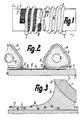
- the heating device 1 has a cylindrical tubular body, preferably of approximately 40 mm outside diameter, which is expediently formed by a section of, for example, a drawn, seamless precision tube with extremely small tolerance deviations its length has a constant inside and outside diameter throughout and is provided with relatively smooth surfaces 4, 5 of low roughness.
- the tubular body 2 is formed by a cylindrical wall 3, which has the outer surface 4 and the inner surface 5.
- the wall could be approximately flat.
- the outer surface 4 serves as a heat input surface for the direct application of temperature by a radiator 6, while the inner surface 5 serves as a heat output surface for the immediate heating of a medium, for example, rinsing or.
- Wash water or fryer fat is used, which is expediently carried as a flowing stream along the surface 5 and, in the case of the heating device 1 being in the form of a channel-shaped flow heater, is expediently conveyed from bottom to top by thermosiphon action with a flow rate dependent on its temperature. If the heating device 1 is switched on as a circulation heater in a circuit, then a separate, in most cases advantageous, conveying device for the medium, for example a pump, could possibly be dispensed with.
- a so-called tubular heater is expediently provided as an electric heater, the outer jacket 7 of which is formed by an essentially closed, thin-walled tube, in which a helical heating wire or heating resistor 8 is embedded in an insulating compound 9 without contact.
- the elongate, strand-shaped radiator 6 can be formed with an almost acute triangular cross section with three convexly rounded corner regions.
- the radiator 6 is wound in the illustrated embodiment in the manner of a helical coil with a constant pitch, so that in view of the heating device 2, radiator sections 14 lying at regular intervals next to one another and approximately parallel to one another are formed.
- the slope is chosen so that adjacent sections 14 a clear distance from each other have, which corresponds to at least about a quarter of the cross-sectional width of the radiator 6 measured parallel to the wall 3, in particular by comparison it is two to eight times larger and expediently lies in the order of magnitude of this cross-sectional width. In the illustrated embodiment, the distance corresponds to approximately three quarters of the cross-sectional width mentioned.
- the cross-sectional height of the radiator 6 measured at right angles to the wall 3 may be larger than the first-mentioned cross-sectional width, but is expediently at least slightly smaller or at most as large.
- the radiator 6 is pre-wound onto an inner diameter that is smaller than the outer diameter of the wall 3, that it can still be expanded in its elastic range at least to the outer diameter of the wall 3 by rotating its ends in the corresponding opposite direction relative to one another about its central axis .
- the radiator 6 is placed on the wall 3 without any problems, after which it elastically narrows again by releasing its ends in such a way that its inner surface lies approximately over its entire length in an envelope surface coinciding with the surface 4, that is to say the inner surface Bears practically without gaps over its length and width and with a radially inward bias on this surface 4
- the heating element 6 forms a helical groove between its sections 14, the bottom surface of which is formed by the surface 4, while its side surfaces are formed by the mutually facing edges of the associated sections 14 and the heating element 6. Due to the described cross-sectional shape of the radiator 6, the helical groove is funnel-shaped in cross-section to the wall 3 up to a region of the smallest width lying relatively close to the wall 3 and the smallest white of this region te up to wall 3 again expanded to a width that is smaller than the largest width on the open side of the spiral groove.
- a flat or ribbon-like heat-conducting body 10 is inserted, the width of which is expediently at least as large as the smallest clear width of the spiral groove, in particular, in comparison, is so much larger that the heat-conducting body 10 on at least one side of the spiral groove as far as from the bottom surface thereof limited inner wider area ranges.
- the heat-conducting body 10 expediently extends at least partially up to directly to the surface 4 of the wall 3 and has a cross-sectional extent measured at right angles to this surface 4, which expediently is at most as large as its cross-sectional extent measured parallel to the wall 3, in particular in contrast it is significantly smaller.
- the heat-conducting body 10 extends to achieve certain heat-conducting characteristics between the inner surface of the heating body 6 and the surface 4 of the wall 3, but in this case it is expedient if the heat-conducting body has thinner edge strips for this purpose, so that it is between the section 14 of the radiator 6, ie in the spiral groove, is thicker.
- the heat-conducting body 10 thus has a different heat-conducting cross-section, at least in the area of the spiral groove, than in the area of the heating body 6.
- the heat-conducting body 10 is embedded in a solder-like fastening means 11, which forms a fastening fluid in a melting state, that is to say generally with appropriate heating, which is so thin that it flows automatically under the weight forces that occur.
- the fastening means 11 forms a composite guiding element with the heat-conducting body 10, in which the fastening means 11 takes up the higher proportion in the exemplary embodiment shown.
- the fastening means 11 is at least partially designed as a heat-conducting layer lying laterally adjacent to the radiator 6 for heat distribution over the associated area of the wall 3, the heat-conducting layer 13 directly adjoining the radiator 6 laterally and in particular with increasing distance from the radiator 6 or from the respective section 14 decreases in thickness, preferably engages laterally via a section 15 wedge-shaped in cross section between the outer jacket 7 of the heating element 6 and the wall 3 or its surface 4.
- the heat-conducting layer 13 is also connected to the wall 3 and the outer jacket 7 with a closed surface in a substantially adherent manner, expediently using a fastening means, for example in the form of a high-temperature-resistant solder for stainless steel, such as a nickel solder of the type that it is used in the wall 3 made of stainless steel and can diffuse into the outer jacket 7, which also consists in particular of stainless or unalloyed steel.
- a fastening means for example in the form of a high-temperature-resistant solder for stainless steel, such as a nickel solder of the type that it is used in the wall 3 made of stainless steel and can diffuse into the outer jacket 7, which also consists in particular of stainless or unalloyed steel.
- the smallest thickness of the layer 13 can be, for example, between one and five tenths of a millimeter, preferably at least two tenths of a millimeter, the greatest thickness of the heat-conducting layer being in particular smaller than the radius of curvature of rounded regions 17 of the cross section of the outer jacket 7, so that the layer 13 is not or only up to in the area of the smallest width of the spiral groove.
- the smallest thickness of the layer 13 is expediently smaller than the thickness of the wall 3, the layer connected to the wall 3 in the manner of a lamination preferably having a specific thermal conductivity coefficient which is several times higher than that of the wall 3.
- the heat-conducting body 10 expediently has an even higher specific heat-conducting coefficient and, compared with the fastening means 11, a higher melting temperature and advantageously consists of a metallic material. With the lateral edge zones, the heat-conducting body 10 extends into the wedge-shaped sections 15.
- the heat-conducting body 10 forms a flat, in particular finely structured, securing element for flowing away during the soldering process, which takes place, for example, in a soldering furnace for the networked engagement of the fastening fluid, this securing element then at least partially in the manner of a reinforcement lying parallel to the layer 13 the fastener 11 is embedded.
- the layer thickness can be determined, in which the fastening means can be built up despite liquefaction by heating, and the proportion which the fastening means occupies in the overall composite of the heat-conducting layer 13 can also be determined.
- the securing function results in particular from utilizing the surface tension of the fastening fluid, which can be achieved, for example, by the securing member having a surface which is enlarged compared to its base area, in particular by at least one layer of a net, a sieve wire, a perforated film, a perforated band, an expanded metal, steel wool or a similarly structured sheet, with any combination of layers of the sheets being conceivable.
- the securing member in that the associated surface of the wall 3 is roughened, for example by means of cording, knurling or a similar, finely structured deformation, in such a way that it secures the fastening means against flowing off during the melting process.
- the outer jacket 6 has a bearing surface 16 which is rectilinear in cross section or in a cylindrical envelope surface, which can be formed by the base side of the triangular cross section and practically by the measures described bears on the surface 4 without a gap.
- this creeps under the resulting capillary pressure between this contact surface 16 and the surface 4, so that here a wafer-thin intermediate layer is formed, the thickness of which corresponds approximately to the width of a capillary gap 18 for the fastening fluid and which practically directly connects the outer jacket 7 with the Wall 3 connects alloying.
- the radiator 6 is arranged in a uniform distribution on part of the wall 3 in the manner described, so that the ends thereof remain free for connecting cables from radiators.
- the flexible or bendable heat-conducting body 10 is wound, which, with sufficient flexural strength, is similarly pre-wound to a narrower diameter, as described with reference to the radiator 6, and then together with the radiator 6 or after or before it Widening to the wall 3 ge pushed so that it jumps resiliently into close contact with the surface 4 after release. 1 shows only the heat-conducting body 10, but not the fastening means 11.
- the fastening means 11 can either be wrapped around the heat-conducting body 10 in the manner of a tape or can already be combined with it in a preparatory work step to form, for example, a plated composite body by rolling or the like. has been at least adhesively connected to the heat-conducting body 10.
- the heating device 1 thus prepared is heated, for example, in a soldering furnace at least up to the melting temperature of the fastener, so that it flows from the areas between the sections 14 into the capillary gaps 18 and through the perforations of the heat-conducting body 10 and, after cooling, in the manner described with the aforementioned Surfaces is intimately connected.
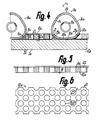
- the heat-conducting body 10a which expediently takes up more volume than the fastening means 11a, is made of a relatively stiff strip material of simple steel sheet or the like which is dimensionally stable in cross section. formed, which may have a thickness in the range of, for example, a little less than 1 mm and more than 2 mm.
- the cross-sectional vertices 20 facing away from the wall 3a namely it has one opposite half of the cross-sectional height of the radiator 6 has a smaller thickness, the thickness of the heat-conducting body 10a, at least in the region of the longitudinal edge surfaces 21 adjoining the radiator 6, being smaller than the radius of curvature of the rounded regions 17a, so that the heat-conducting body 10a can be snapped resiliently between adjacent sections 14a .
- the longitudinal edge surfaces 21 extend substantially to the side of the outer casing 7a of the radiator 6a.
- the flat side 12a of the heat-conducting body 10a which is linear in cross-section or lies in a cylindrical envelope surface, lies essentially over the entire width of the heat-conducting body 10a only at a substantially constant capillary gap distance from the surface 4a, so that this flat side 12a is not broken through Areas over a wafer-thin, essentially uninterrupted layer 19 of the fastening means are almost directly touching or are connected to the surface 4a by alloying diffusion.
- This layer 19 merges seamlessly into the wedge-shaped sections 15a and from there into the capillary gaps 18a, the fastening means 11a completely filling the space delimited by a rounded corner region 17a, an opposite longitudinal edge surface 21 and the surface 4a and also intimately with the longitudinal edge surface 21 connected is.
- the longitudinal edge surface 21a can also be adapted to the contour of the opposite corner area 17a in such a way that less fastening means is required for the area corresponding to section 15a, because this area is at least partially filled with the heat-conducting body 10a .
- the longitudinal edge surface 21a can be designed so that the flat side 19 of the heat-conducting body 10a is wider than the side facing away from the wall 3a or it can be adapted so closely to the contour of the corner region 17a that there is almost only one capillary gap for the receptacle of the fastener remains free. With the heat conducting body 10a the sections 14a of the radiator 6a can thus also be kept at a precise distance before being attached to the wall 3a.
- the heat-conducting body 10a is provided with openings 22 extending from its flat side 12a, which in the exemplary embodiment shown are evenly distributed over the base area of the heat-conducting body 10a in the manner of a grid perforation and are provided as continuous openings of constant width over its entire thickness.
- the fastening means or the fastening fluid also creeps at least in layers on the surfaces delimiting these openings 22, as well as on all other surfaces, so that the heat-conducting body 10a is practically completely sealed by at least one thin layer of the fastening means 11a.
- the openings 22 can also be partially or completely filled with the fastener.
- the heat-conducting body 10a has viewing windows 23 which are uniformly distributed over its longitudinal edges 21 in the form of cut-outs which can be V-shaped, rectangular or similar, for example, and which serve to determine optically in the region of these longitudinal edge surfaces 21 in a simple manner to be able to determine whether the fastening means has sufficiently filled the cavities adjoining the longitudinal edge surfaces 21.
- the viewing windows 23 are formed by the perforation forming the openings 22 in that the longitudinal edge surface 21 is placed in an area in which a row of the perforations is cut in such a way that semicircular viewing windows 23 are formed, which are distributed in a manner corresponding to the perforation grid are provided.
- the heat-conducting body 10a can already be connected to the fastening means 11a applied as a layer, for example by plating, in a preparatory work step, the fastening means 11a expediently being attached to the side of the heat-conducting body 10a facing away from the flat side 19 before the perforation is produced and then the perforation which also penetrates the fastening means 11a is produced.
- the heat-conducting body 10a is provided with such a large amount of fastening means 11a that no further solder has to be added in addition, but that the solder present on the heat-conducting body 10a is also sufficient to fasten the heating body 6a in the manner described.
- solder Since the solder is on the side of the heat-conducting body 10a facing away from the flat side 19, when it melts, it flows from this side through the openings 22 and in the region of the longitudinal edge surface 21 to the surface 4a, the coating of the heat-conducting body 10a and the fastening described of the radiator 6a and the heat sink 10a.
- a nickel or V2A mesh in the form of, for example, a sieve wire can also be attached between the sections of the radiator and a solder foil can therefore be wound around it.
- the screen wire can also be rolled into a copper foil. It is particularly expedient to use a heat-conducting sheet metal strip of approximately 0.3 to 0.5 mm in thickness as the heat-conducting body.
- the width of the heat-conducting body can be, for example, approximately 6 mm and it can have perforations of 2.5 to 3 mm in diameter, the holes being provided, for example, at a distance of 5 to 6 mm.
- the holes can also have smaller diameters, it being particularly expedient if the perforation acts like a sieve on the fastening fluid.
- a temperature sensor of a temperature controller or a temperature limiter is also to be attached to the wall 3a, this is expediently flat if arranged on the surface 4a and formed by an elongated, tubular temperature sensor of a system filled with an expansion liquid.
- the temperature sensor can be expediently inserted in a U-shaped support profile, which is attached to the outside of its crossbar via a capillary gap-thick layer of the fastener on the surface 4a and whose profile leg can be bent tightly around the temperature sensor so that it can be bent to more than half of its circumference and its length, in particular essentially enclosed over its entire circumference and its entire length by the support profile.
- the temperature sensor is also strongly influenced by this section 14a and not only by the temperature of the wall 3a and thus responds particularly quickly in the event of overheating.
- the support profile or the temperature sensor it is instead conceivable to arrange the support profile or the temperature sensor approximately in the middle between two adjacent sections 14a of the tubular heating element, the arrangement being immediate the associated side of the heat-conducting element 10a or on the surface 4a can take place in such a way that the supporting profile is flanked on at least one side by a correspondingly narrower heat-conducting element, which on the one hand the heat distribution in the wall 3a and on the other hand as a heat-conducting bridge between the temperature sensor and the associated section 14a of the radiator 6a is used.
- the support profile can also be tubular.
Landscapes
- Resistance Heating (AREA)
- Instantaneous Water Boilers, Portable Hot-Water Supply Apparatuses, And Control Of Portable Hot-Water Supply Apparatuses (AREA)
Applications Claiming Priority (2)
| Application Number | Priority Date | Filing Date | Title |
|---|---|---|---|
| DE19873718836 DE3718836A1 (de) | 1987-06-05 | 1987-06-05 | Heizvorrichtung mit einem elektrischen heizkoerper |
| DE3718836 | 1987-06-05 |
Publications (2)
| Publication Number | Publication Date |
|---|---|
| EP0293681A2 true EP0293681A2 (fr) | 1988-12-07 |
| EP0293681A3 EP0293681A3 (fr) | 1990-09-12 |
Family
ID=6329112
Family Applications (1)
| Application Number | Title | Priority Date | Filing Date |
|---|---|---|---|
| EP19880108042 Withdrawn EP0293681A3 (fr) | 1987-06-05 | 1988-05-19 | Dispositif de chauffage avec un élément chauffant électrique |
Country Status (5)
| Country | Link |
|---|---|
| US (1) | US4980537A (fr) |
| EP (1) | EP0293681A3 (fr) |
| JP (1) | JPS63310590A (fr) |
| DE (1) | DE3718836A1 (fr) |
| YU (1) | YU107888A (fr) |
Cited By (2)
| Publication number | Priority date | Publication date | Assignee | Title |
|---|---|---|---|---|
| EP0739153A1 (fr) * | 1995-04-19 | 1996-10-23 | Seb S.A. | Elément chauffant brasé sur support |
| EP0848576A3 (fr) * | 1996-12-09 | 1998-11-25 | Sheathed Heating Elements Limited | Dispositif de chauffage électrique |
Families Citing this family (6)
| Publication number | Priority date | Publication date | Assignee | Title |
|---|---|---|---|---|
| USD360027S (en) | 1991-09-25 | 1995-07-04 | Siemens Aktiengesellschaft | Dehumidifier unit for use in a patient ventilator |
| US5224973A (en) * | 1992-04-20 | 1993-07-06 | Donaldson Company, Inc. | Filter cartridge for trap apparatus |
| DE19605996C2 (de) * | 1996-02-17 | 2000-10-19 | Tuerk & Hillinger Gmbh | Verfahren zur Herstellung elektrischer Durchlauferhitzer für flüssige Medien |
| DE50109139D1 (de) * | 2000-10-25 | 2006-05-04 | Eichenauer Heizelemente Gmbh | Pumpe mit einem beheizbaren Gehäuse |
| ITVE20060016U1 (it) * | 2006-05-18 | 2007-11-19 | Irca Spa | Elemento riscaldante.- |
| TR201906525T4 (tr) * | 2013-06-26 | 2019-05-21 | Nestec Sa | İçecek veya Gıda Hazırlama Makinesi İçin Hacim Esaslı Isıtma Cihazı. |
Family Cites Families (15)
| Publication number | Priority date | Publication date | Assignee | Title |
|---|---|---|---|---|
| DE8437042U1 (de) * | 1985-03-21 | Elpag Ag Chur, Chur | Durchlauferhitzer | |
| US2443577A (en) * | 1943-10-04 | 1948-06-15 | Garrett Corp | Method of brazing tube ends |
| US2694852A (en) * | 1951-01-13 | 1954-11-23 | Riley Stoker Corp | Method of brazing and the product thereof |
| DE1132883B (de) * | 1957-01-30 | 1962-07-12 | Franciscus Roffelsen | Verfahren zum Herstellung von Waermeaustauschelementen |
| DE1139589B (de) * | 1960-02-10 | 1962-11-15 | Siemens Elektrogeraete Gmbh | Elektrischer Durchlauferhitzer, bei dem die durchstroemende Fluessigkeit von schraubenfoermig eng aneinanderliegend angeordneten Rohrheizkoerpern erhitzt wird |
| DE1401676A1 (de) * | 1961-05-23 | 1968-10-24 | Kress Dr Ing Herwig | Verfahren zur Berippung von Waermeaustauschflaechen mit Wellbaendern |
| US3398262A (en) * | 1967-09-14 | 1968-08-20 | Electro Trace Corp | Pipe heating arrangement |
| DE1902575B2 (de) * | 1969-01-20 | 1971-06-03 | Elektrische heizeinheit | |
| JPS4834259B1 (fr) * | 1970-07-16 | 1973-10-19 | ||
| US4123837A (en) * | 1976-02-12 | 1978-11-07 | Exxon Research & Engineering Co. | Heat transfer method |
| DE2805093C2 (de) * | 1978-02-07 | 1982-11-18 | E.G.O. Elektro-Geräte Blanc u. Fischer, 7519 Oberderdingen | Halterung eines Heizelementes für die indirekte elektrische Beheizung eines Wassererhitzers |
| DE3040463A1 (de) * | 1980-10-27 | 1982-05-13 | Bosch-Siemens Hausgeräte GmbH, 7000 Stuttgart | Mechanische verbindung eines elektrischen rohrheizkoerpers mit einer zu beheizenden flaeche |
| DE3221348A1 (de) * | 1982-06-05 | 1983-12-08 | E.G.O. Elektro-Geräte Blanc u. Fischer, 7519 Oberderdingen | Heizelement mit zylindrischer wandung |
| CH658356A5 (de) * | 1982-12-08 | 1986-10-31 | Jura Elektroapparate Fab | Heizvorrichtung und verfahren zur herstellung derselben. |
| DE3347160A1 (de) * | 1983-12-27 | 1985-08-29 | Türk & Hillinger GmbH, 7200 Tuttlingen | Elektrische heizeinrichtung fuer kunststoffspritzduesen |
-
1987
- 1987-06-05 DE DE19873718836 patent/DE3718836A1/de not_active Withdrawn
-
1988
- 1988-05-19 EP EP19880108042 patent/EP0293681A3/fr not_active Withdrawn
- 1988-05-27 US US07/199,949 patent/US4980537A/en not_active Expired - Fee Related
- 1988-06-01 JP JP63132921A patent/JPS63310590A/ja active Pending
- 1988-06-02 YU YU01078/88A patent/YU107888A/xx unknown
Cited By (3)
| Publication number | Priority date | Publication date | Assignee | Title |
|---|---|---|---|---|
| EP0739153A1 (fr) * | 1995-04-19 | 1996-10-23 | Seb S.A. | Elément chauffant brasé sur support |
| FR2733383A1 (fr) * | 1995-04-19 | 1996-10-25 | Seb Sa | Element chauffant brase sur support |
| EP0848576A3 (fr) * | 1996-12-09 | 1998-11-25 | Sheathed Heating Elements Limited | Dispositif de chauffage électrique |
Also Published As
| Publication number | Publication date |
|---|---|
| DE3718836A1 (de) | 1989-01-12 |
| JPS63310590A (ja) | 1988-12-19 |
| US4980537A (en) | 1990-12-25 |
| YU107888A (en) | 1991-02-28 |
| EP0293681A3 (fr) | 1990-09-12 |
Similar Documents
| Publication | Publication Date | Title |
|---|---|---|
| DE2728971C3 (de) | Einsatz für ein Wärmetauscherrohr | |
| DE2719273C3 (de) | Wärmetauscher | |
| DE69124062T2 (de) | Heizvorrichtung, speziell in Form eines Bandes oder Streifens | |
| DE2542162B2 (de) | Heiztorpedo für Spritzgießmaschinen | |
| DE2403538B2 (de) | Wärmerohr | |
| DE3902206A1 (de) | Vorrichtung zum erhitzen von gasen | |
| EP0585831A2 (fr) | Elément chauffant, en particulier pour appareils de cuisine | |
| DE20215960U1 (de) | Elektrische Heizpatrone für zylindrische Körper | |
| DE2731027C2 (de) | Verfahren zur Herstellung von dünnwandigen Metallrohren | |
| EP0293681A2 (fr) | Dispositif de chauffage avec un élément chauffant électrique | |
| DE69010458T2 (de) | Heizbänder. | |
| DE1765917C3 (de) | Bandförmiger, aus Supraleitermaterial und elektrisch normalleitendem Metall bestehender Leiter | |
| DE3021461C2 (fr) | ||
| DE2823059A1 (de) | Temperaturfuehlvorrichtung, insbesondere fuer geraete zur erwaermung oder erhitzung von nahrungsmitteln | |
| DE2340489A1 (de) | Elektrischer durchflusserhitzer | |
| DE10059885C1 (de) | Elektrischer Durchlauferhitzer | |
| DE3407965A1 (de) | Grillplatte | |
| DE3541641A1 (de) | Rohrheizkoerper-heizeinrichtung sowie verfahren zu deren herstellung | |
| DE29504105U1 (de) | Temperaturfühler | |
| DE3213619C2 (de) | Fluidheizvorrichtung | |
| EP1070922A2 (fr) | Appareil de chauffage avec régulation de température de lessive | |
| DE2549006C3 (de) | Elektrisches Heizelement | |
| DE2843385C2 (de) | Verfahren zum Verbinden der Bandenden eines Kunststoffbandes | |
| DE69617922T2 (de) | Elektrische Heizanordnung und ihr Herstellungsverfahren | |
| DE1489287A1 (de) | Einfaches und mehrfaches Thermoelement |
Legal Events
| Date | Code | Title | Description |
|---|---|---|---|
| PUAI | Public reference made under article 153(3) epc to a published international application that has entered the european phase |
Free format text: ORIGINAL CODE: 0009012 |
|
| AK | Designated contracting states |
Kind code of ref document: A2 Designated state(s): AT CH DE ES FR GB GR IT LI SE |
|
| PUAL | Search report despatched |
Free format text: ORIGINAL CODE: 0009013 |
|
| AK | Designated contracting states |
Kind code of ref document: A3 Designated state(s): AT CH DE ES FR GB GR IT LI SE |
|
| 17P | Request for examination filed |
Effective date: 19901129 |
|
| STAA | Information on the status of an ep patent application or granted ep patent |
Free format text: STATUS: THE APPLICATION IS DEEMED TO BE WITHDRAWN |
|
| 18D | Application deemed to be withdrawn |
Effective date: 19930105 |