EP0294094A2 - Dispositif pour rogner des articles tubulaires - Google Patents
Dispositif pour rogner des articles tubulaires Download PDFInfo
- Publication number
- EP0294094A2 EP0294094A2 EP88304744A EP88304744A EP0294094A2 EP 0294094 A2 EP0294094 A2 EP 0294094A2 EP 88304744 A EP88304744 A EP 88304744A EP 88304744 A EP88304744 A EP 88304744A EP 0294094 A2 EP0294094 A2 EP 0294094A2
- Authority
- EP
- European Patent Office
- Prior art keywords
- article
- die
- punch
- flanged
- flanged end
- Prior art date
- Legal status (The legal status is an assumption and is not a legal conclusion. Google has not performed a legal analysis and makes no representation as to the accuracy of the status listed.)
- Withdrawn
Links
- 238000009966 trimming Methods 0.000 title claims description 37
- 230000033001 locomotion Effects 0.000 claims description 30
- 238000000034 method Methods 0.000 claims description 4
- 230000008933 bodily movement Effects 0.000 claims description 3
- 230000000694 effects Effects 0.000 claims description 2
- 239000004033 plastic Substances 0.000 description 6
- 229920003023 plastic Polymers 0.000 description 6
- 230000006835 compression Effects 0.000 description 4
- 238000007906 compression Methods 0.000 description 4
- 230000000712 assembly Effects 0.000 description 3
- 238000000429 assembly Methods 0.000 description 3
- 239000000463 material Substances 0.000 description 3
- 239000002184 metal Substances 0.000 description 3
- 238000004519 manufacturing process Methods 0.000 description 2
- 229920000139 polyethylene terephthalate Polymers 0.000 description 2
- 239000005020 polyethylene terephthalate Substances 0.000 description 2
- 235000013361 beverage Nutrition 0.000 description 1
- 238000010276 construction Methods 0.000 description 1
- 238000004806 packaging method and process Methods 0.000 description 1
- -1 polyethylene terephthalate Polymers 0.000 description 1
- 238000004064 recycling Methods 0.000 description 1
- 238000004826 seaming Methods 0.000 description 1
- 238000010008 shearing Methods 0.000 description 1
Images



Classifications
-
- B—PERFORMING OPERATIONS; TRANSPORTING
- B23—MACHINE TOOLS; METAL-WORKING NOT OTHERWISE PROVIDED FOR
- B23D—PLANING; SLOTTING; SHEARING; BROACHING; SAWING; FILING; SCRAPING; LIKE OPERATIONS FOR WORKING METAL BY REMOVING MATERIAL, NOT OTHERWISE PROVIDED FOR
- B23D31/00—Shearing machines or shearing devices covered by none or more than one of the groups B23D15/00 - B23D29/00; Combinations of shearing machines
- B23D31/001—Shearing machines or shearing devices covered by none or more than one of the groups B23D15/00 - B23D29/00; Combinations of shearing machines for trimming deep drawn products
-
- Y—GENERAL TAGGING OF NEW TECHNOLOGICAL DEVELOPMENTS; GENERAL TAGGING OF CROSS-SECTIONAL TECHNOLOGIES SPANNING OVER SEVERAL SECTIONS OF THE IPC; TECHNICAL SUBJECTS COVERED BY FORMER USPC CROSS-REFERENCE ART COLLECTIONS [XRACs] AND DIGESTS
- Y10—TECHNICAL SUBJECTS COVERED BY FORMER USPC
- Y10T—TECHNICAL SUBJECTS COVERED BY FORMER US CLASSIFICATION
- Y10T83/00—Cutting
- Y10T83/04—Processes
- Y10T83/0524—Plural cutting steps
-
- Y—GENERAL TAGGING OF NEW TECHNOLOGICAL DEVELOPMENTS; GENERAL TAGGING OF CROSS-SECTIONAL TECHNOLOGIES SPANNING OVER SEVERAL SECTIONS OF THE IPC; TECHNICAL SUBJECTS COVERED BY FORMER USPC CROSS-REFERENCE ART COLLECTIONS [XRACs] AND DIGESTS
- Y10—TECHNICAL SUBJECTS COVERED BY FORMER USPC
- Y10T—TECHNICAL SUBJECTS COVERED BY FORMER US CLASSIFICATION
- Y10T83/00—Cutting
- Y10T83/04—Processes
- Y10T83/0596—Cutting wall of hollow work
-
- Y—GENERAL TAGGING OF NEW TECHNOLOGICAL DEVELOPMENTS; GENERAL TAGGING OF CROSS-SECTIONAL TECHNOLOGIES SPANNING OVER SEVERAL SECTIONS OF THE IPC; TECHNICAL SUBJECTS COVERED BY FORMER USPC CROSS-REFERENCE ART COLLECTIONS [XRACs] AND DIGESTS
- Y10—TECHNICAL SUBJECTS COVERED BY FORMER USPC
- Y10T—TECHNICAL SUBJECTS COVERED BY FORMER US CLASSIFICATION
- Y10T83/00—Cutting
- Y10T83/384—By tool inside hollow work
- Y10T83/391—With means to position tool[s] for cutting
-
- Y—GENERAL TAGGING OF NEW TECHNOLOGICAL DEVELOPMENTS; GENERAL TAGGING OF CROSS-SECTIONAL TECHNOLOGIES SPANNING OVER SEVERAL SECTIONS OF THE IPC; TECHNICAL SUBJECTS COVERED BY FORMER USPC CROSS-REFERENCE ART COLLECTIONS [XRACs] AND DIGESTS
- Y10—TECHNICAL SUBJECTS COVERED BY FORMER USPC
- Y10T—TECHNICAL SUBJECTS COVERED BY FORMER US CLASSIFICATION
- Y10T83/00—Cutting
- Y10T83/384—By tool inside hollow work
- Y10T83/395—One tool having only rectilinear motion[s]
- Y10T83/396—Annulus and disc-type tool pair
-
- Y—GENERAL TAGGING OF NEW TECHNOLOGICAL DEVELOPMENTS; GENERAL TAGGING OF CROSS-SECTIONAL TECHNOLOGIES SPANNING OVER SEVERAL SECTIONS OF THE IPC; TECHNICAL SUBJECTS COVERED BY FORMER USPC CROSS-REFERENCE ART COLLECTIONS [XRACs] AND DIGESTS
- Y10—TECHNICAL SUBJECTS COVERED BY FORMER USPC
- Y10T—TECHNICAL SUBJECTS COVERED BY FORMER US CLASSIFICATION
- Y10T83/00—Cutting
- Y10T83/444—Tool engages work during dwell of intermittent workfeed
- Y10T83/463—Work-feed element contacts and moves with work
-
- Y—GENERAL TAGGING OF NEW TECHNOLOGICAL DEVELOPMENTS; GENERAL TAGGING OF CROSS-SECTIONAL TECHNOLOGIES SPANNING OVER SEVERAL SECTIONS OF THE IPC; TECHNICAL SUBJECTS COVERED BY FORMER USPC CROSS-REFERENCE ART COLLECTIONS [XRACs] AND DIGESTS
- Y10—TECHNICAL SUBJECTS COVERED BY FORMER USPC
- Y10T—TECHNICAL SUBJECTS COVERED BY FORMER US CLASSIFICATION
- Y10T83/00—Cutting
- Y10T83/869—Means to drive or to guide tool
- Y10T83/8748—Tool displaceable to inactive position [e.g., for work loading]
-
- Y—GENERAL TAGGING OF NEW TECHNOLOGICAL DEVELOPMENTS; GENERAL TAGGING OF CROSS-SECTIONAL TECHNOLOGIES SPANNING OVER SEVERAL SECTIONS OF THE IPC; TECHNICAL SUBJECTS COVERED BY FORMER USPC CROSS-REFERENCE ART COLLECTIONS [XRACs] AND DIGESTS
- Y10—TECHNICAL SUBJECTS COVERED BY FORMER USPC
- Y10T—TECHNICAL SUBJECTS COVERED BY FORMER US CLASSIFICATION
- Y10T83/00—Cutting
- Y10T83/869—Means to drive or to guide tool
- Y10T83/8752—Tool moves work to and against cooperating tool
-
- Y—GENERAL TAGGING OF NEW TECHNOLOGICAL DEVELOPMENTS; GENERAL TAGGING OF CROSS-SECTIONAL TECHNOLOGIES SPANNING OVER SEVERAL SECTIONS OF THE IPC; TECHNICAL SUBJECTS COVERED BY FORMER USPC CROSS-REFERENCE ART COLLECTIONS [XRACs] AND DIGESTS
- Y10—TECHNICAL SUBJECTS COVERED BY FORMER USPC
- Y10T—TECHNICAL SUBJECTS COVERED BY FORMER US CLASSIFICATION
- Y10T83/00—Cutting
- Y10T83/869—Means to drive or to guide tool
- Y10T83/8752—Tool moves work to and against cooperating tool
- Y10T83/8756—Work forced through tool aperture or between spaced cooperating tools
-
- Y—GENERAL TAGGING OF NEW TECHNOLOGICAL DEVELOPMENTS; GENERAL TAGGING OF CROSS-SECTIONAL TECHNOLOGIES SPANNING OVER SEVERAL SECTIONS OF THE IPC; TECHNICAL SUBJECTS COVERED BY FORMER USPC CROSS-REFERENCE ART COLLECTIONS [XRACs] AND DIGESTS
- Y10—TECHNICAL SUBJECTS COVERED BY FORMER USPC
- Y10T—TECHNICAL SUBJECTS COVERED BY FORMER US CLASSIFICATION
- Y10T83/00—Cutting
- Y10T83/869—Means to drive or to guide tool
- Y10T83/8776—Constantly urged tool or tool support [e.g., spring biased]
- Y10T83/8785—Through return [noncutting] stroke
-
- Y—GENERAL TAGGING OF NEW TECHNOLOGICAL DEVELOPMENTS; GENERAL TAGGING OF CROSS-SECTIONAL TECHNOLOGIES SPANNING OVER SEVERAL SECTIONS OF THE IPC; TECHNICAL SUBJECTS COVERED BY FORMER USPC CROSS-REFERENCE ART COLLECTIONS [XRACs] AND DIGESTS
- Y10—TECHNICAL SUBJECTS COVERED BY FORMER USPC
- Y10T—TECHNICAL SUBJECTS COVERED BY FORMER US CLASSIFICATION
- Y10T83/00—Cutting
- Y10T83/929—Tool or tool with support
- Y10T83/9411—Cutting couple type
- Y10T83/9423—Punching tool
- Y10T83/9425—Tool pair
-
- Y—GENERAL TAGGING OF NEW TECHNOLOGICAL DEVELOPMENTS; GENERAL TAGGING OF CROSS-SECTIONAL TECHNOLOGIES SPANNING OVER SEVERAL SECTIONS OF THE IPC; TECHNICAL SUBJECTS COVERED BY FORMER USPC CROSS-REFERENCE ART COLLECTIONS [XRACs] AND DIGESTS
- Y10—TECHNICAL SUBJECTS COVERED BY FORMER USPC
- Y10T—TECHNICAL SUBJECTS COVERED BY FORMER US CLASSIFICATION
- Y10T83/00—Cutting
- Y10T83/929—Tool or tool with support
- Y10T83/9411—Cutting couple type
- Y10T83/9423—Punching tool
- Y10T83/9428—Shear-type male tool
Definitions
- the present invention relates generally to apparatus for trimming the ends of a tubular article which is outwardly flanged at both ends and has particular, but not exclusive, application for trimming the outwardly flanged ends of a plastics body for a food or beverage container, prior to double seaming the flanged ends to a metal end closure.
- trimming is effected by relative movement of a punch and die along the axis of the tubular article, the relative movement causing the punch and die to cooperate through the article wall at the flanged end and so to trim the flanged end by a shearing action.
- the die is required to engage the flanged end at the generally exterior surface of the article, and it is therefore formed as a plurality of segments which can be closed together over the flanged end for the trimming operation, and subsequently opened after trimming to allow the trimmed article to be readily removed.
- the present invention seeks to provide a method and apparatus which overcomes this difficulty and enables both the outwardly flanged ends of a tubular article to be rapidly and accurately trimmed using segmented dies which are fixed and accurately located in axial position, and using punches which are moved axially in relation to the dies for cooperation therewith.
- the invention provides apparatus for trimming the ends of a tubular article which is outwardly flanged at both ends which comprises for each said flanged end, a die and a punch having respective cutting edges capable of trimming the flanged end to a desired dimension by mutual cooperation through the article wall, the die being comprised of a plurality of segments which are relatively movable between a separated position at which the flanged end may be inserted between them and a closed, die-forming position at which the cutting edge may operatively engage the flanged end at the punch being movable axially of the article when the die is closed, from a retracted position in which it is spaced from the article to an operative position in which it performs the trimming operation on the respective flanged end by cooperation with the die, the said axial movements of the two punches to achieve trimming of the respective flanged ends being each accompanied by an axial movement of the flanged end in the same direction as the punch, and drive means being provided and arranged for operating
- the invention provides a method of trimming the ends of a tubular article which is outwardly flanged at both ends, which comprises:-
- the apparatus is designed to operate upon the outwardly flanged ends of open-ended and generally cylindrical plastics articles which are destined to form the bodies of packaging containers.
- One such article A is shown in part in Figure 3.
- the apparatus is arranged to trim the flanged ends of successive articles to a desired diameter so that they may make reliable double-seam connections with conventional metal end closures.
- the tubular articles are formed of PET (polyethylene terephthalate) and are heat-set to enable them to withstand thermal processing of the containers into which they are to be incorporated.
- the apparatus comprises a first punch assembly 1 and a second punch assembly 2 aligned along the central axis of the apparatus.
- a first die 3 is associated with the punch assembly 1 and a second die 4 is associated with the punch assembly 2. Constructional details of the punch assemblies and the dies are shown in Figures 3 and 4.
- the drive arrangement for the apparatus is also shown diagrammatically in Figure 1.
- Primary drive is provided by a variable speed electric motor having an output shaft 6 telescopically connected to drive shaft 7 by means of a connecting shaft 106 having a non-circular cross-section.
- Drive shaft 7 is connected through a right-angle drive box 8 to camshaft 9 which is in turn connected through a right-angle drive box 10 to drive shaft 11.
- Drive shaft 11 is telescopically coupled to a drive shaft 12 by means of a connecting shaft 111 having a non-circular cross-section, and drive shaft 12 is coupled through a right-angle gear box 13 to camshaft 14.
- the drive shafts are supported in bearings 15 and each carries a die operating cam 16 mounted for rotation therewith and arranged for operating upon respective segments 41, 42 of the dies 3, 4.
- the camshafts 9, 14 are arranged to drive the punches 35 of the punch assemblies 2, 1 respectively by means of cam following rollers 71 and associated longitudinally movable shafts 37.
- compression springs 70 acting on the shafts 37 bias the cam rollers against the cam surfaces and bias the punches towards their retracted positions.
- the apparatus is mounted on a main frame 17.
- the second punch assembly 2 with its associated die 4 and drive elements is mounted on a sub-frame 18 which is movable along the central axis of the apparatus on the main frame 17 by means of rollers 19 to allow the apparatus to be adjusted for trimming articles of different lengths.
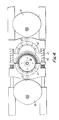
- FIG 2 shows a conveyor 24 arranged for delivering the tubular articles or workpieces to the work station of the apparatus at which they are in axial alignment with the two punch assemblies.
- the conveyor 24 comprises an elongate flexible belt 25 driven around pulley wheels 26, 27 and 28.
- Pulley wheel 28 is belt driven from an input shaft 29 which in turn is driven from an indexing drive box 20 shown in phantom in Figure 1.
- the indexing drive box 20 is itself driven from the output shaft 6 of the electric motor 5.
- a plurality of holders 30 are spaced along the belt 25 and in a downward run of the conveyor (shown in the centre of Figure 2) the holders 30 are guided by a guide 31 and cooperate in pairs to support the articles to be trimmed and to deliver them one at a time to the work station.
- the conveyor is driven in indexing motion from the indexing drive box 20 to move the articles into position at the work station when the dies are in the open position shown in Figure 2.
- the holders support the articles radially whilst the dies are closed and the ends of the articles are trimmed by operation of the punches.
- Articles to be trimmed are delivered to the conveyor 24 at a point where it passes around the upper pulley wheel 26.
- Each punch 35 comprises a punch head 36 supported on a cylindrical shaft 37.
- the punch head 36 is bolted to the shaft 37 and has mounted thereon a cutting ring 38 contoured in accordance with the radially inner portion of the flanged end of a tubular article to be trimmed and providing a cutting edge 39 which cooperates with a cutting edge 40 provided on the die segments 41 and 42 to sever the flange of the article A when the punch 35 is advanced.
- the two segments 41 and 42 of the die are urged radially along guide bars 43 into their closed, die forming position, by means of the cams 16 and against the action of springs 44.
- the cam surfaces of the cams bear on cam follower rollers 45 carried by the die segments as shown in Figure 4.
- Each punch 35 is mounted for reciprocal motion along its axis and is supported in a cylindrical bearing sleeve 50.
- Each punch is reciprocated by means of a cam 51 (see Figure 5) mounted on the respective camshaft 9 and 14 and acting against a return spring 70.
- the cams 51 are followed by rollers 71 mounted on the ends of the punch shafts 37.
- a clamping ring 52 is mounted to slide on the shaft 37 and is urged towards the punch head 35 by means of a compression spring 53.
- the clamping ring 52 is provided with an annular extension or nose 54 which engages in a corresponding groove 55 formed in the segments 41 and 42 when the die is closed and the punch is advanced.
- the clamping ring holds the segments of the die securely together and retains the punch and die in correct alignment while the flanged end of the article A is being trimmed.
- a flange support and ejection ring 60 is mounted for sliding movement on the punch head 35 under the action of a compression spring 61 and serves to support the radially outer portion of the flanged end of the article during the trimming operation. Advance of the punch 35 beyond the position shown on the left in Figure 3 causes the cutting edges 39 and 40 cooperate to sever, and thus trim the flanged end at a required diameter.
- the punch 35 of the first punch assembly 1 is advanced by operation of the respective cam 51 to the position shown on the left in Figure 3 where the annular nose 54 of the clamping ring becomes engaged in the groove 55 on the die as explained above.
- the ejection ring 60 provides axial restraint and location for the flanged end during the trimming operation and afterwards, while the punch continues its advance for a short distance sufficient to ensure severance and then returns, holding the trimmed ring of plastics material resiliently against the respective die 3, 4 to prevent it from fouling the punch while the latter is in movement.
- the die After retraction of the punch the die preferably remains held closed by its respective cams 16, so that the trim ring continues to be held captive within the die; furthermore, the die provides radial restraint for the trimmed end of the tubular article during the trimming operation which is subsequently to be performed on the other end.
- the flanged end being trimmed is required to move with the punch 35 through a small distance, the die 3 or 4 being stationary.
- the holders 30 are arranged to permit a limited bodily axial movement of the article A in each direction, and a small difference, e.g. 1/16th of a revolution, is introduced between the angular positions of the cams 51 on their camshafts 9, 14 so that the trimming operations are performed sequentially; the article A therefore moves axially in one direction and then the other as the trimming operations are carried out.
- the advancing movement of the second punch 35 is overlapped in time relation with the retraction of the first punch.
- the trimming operation upon the second flanged end of the article A is performed in an identical way to the first, the article moving axially back through its holders 30 to its original axial position.
- the dies 3, 4 are simultaneously allowed by their respective cams 16 to open under the action of their compression springs 44.
- the rings of plastics material trimmed from the flanged ends are thereby released, and drop from the apparatus to a suitable discharge receptacle or conveyor for the subsequent recycling if desired.
- the trimmed article A is removed from the work station by the next indexing movement of the conveyor 24, and subsequently released from the holders 30 for discharge from the apparatus by suitable means.
- the dies 3, 4 are fixed in axial position and their relative spacing can be accurately set and maintained in relation to the length of the article A so as to achieve trimming within closely defined limits.
- the closing movements of the dies and the advancing movements of the punches 35 to their operative positions are achieved by a common drive system which substantially obviates any risk of maloperation or loss of synchronisation once the apparatus has been properly set up. Applicants accordingly believe that the apparatus shown and described will be capable of trimming the tubular articles A reliably at high rates of production and with good accuracy.
- the invention may be applied to the trimming of the outwardly flanged ends of tubular articles of metal and other non-plastics materials.
Landscapes
- Engineering & Computer Science (AREA)
- Mechanical Engineering (AREA)
- Perforating, Stamping-Out Or Severing By Means Other Than Cutting (AREA)
- Nonmetal Cutting Devices (AREA)
Applications Claiming Priority (2)
| Application Number | Priority Date | Filing Date | Title |
|---|---|---|---|
| GB8713000A GB2205269B (en) | 1987-06-03 | 1987-06-03 | Apparatus for trimming a tubular article |
| GB8713000 | 1987-06-03 |
Publications (2)
| Publication Number | Publication Date |
|---|---|
| EP0294094A2 true EP0294094A2 (fr) | 1988-12-07 |
| EP0294094A3 EP0294094A3 (fr) | 1990-09-05 |
Family
ID=10618317
Family Applications (1)
| Application Number | Title | Priority Date | Filing Date |
|---|---|---|---|
| EP19880304744 Withdrawn EP0294094A3 (fr) | 1987-06-03 | 1988-05-25 | Dispositif pour rogner des articles tubulaires |
Country Status (8)
| Country | Link |
|---|---|
| US (1) | US4843930A (fr) |
| EP (1) | EP0294094A3 (fr) |
| JP (1) | JP2620705B2 (fr) |
| AU (1) | AU595117B2 (fr) |
| BR (1) | BR8802597A (fr) |
| GB (1) | GB2205269B (fr) |
| NZ (1) | NZ224858A (fr) |
| ZA (1) | ZA883690B (fr) |
Cited By (1)
| Publication number | Priority date | Publication date | Assignee | Title |
|---|---|---|---|---|
| EP0850743A1 (fr) * | 1996-11-27 | 1998-07-01 | Kunststoff- und Umwelttechnik GmbH | Procédé de conditionnement et traitement de matières plastiques, en particulier de polyvinylbutyral, et manufacture du produit recyclé |
Families Citing this family (6)
| Publication number | Priority date | Publication date | Assignee | Title |
|---|---|---|---|---|
| AU622308B2 (en) * | 1989-04-17 | 1992-04-02 | Jetra Engineering Pty Ltd | Method and apparatus for cutting and trimming plastic pot |
| US5694822A (en) * | 1993-08-16 | 1997-12-09 | Reynolds Metals Company | Apparatus for trimming can bodies |
| EP0648566A1 (fr) * | 1993-08-16 | 1995-04-19 | Reynolds Metals Company | Appareil et methode pour couper des pieces creuses |
| US7441486B2 (en) * | 2004-10-01 | 2008-10-28 | Graham Engineering Corp. | Bottle trimmer and method |
| WO2006054694A1 (fr) * | 2004-11-19 | 2006-05-26 | Amada Company, Limited | Matrice de poinçonnage |
| CN103273515B (zh) * | 2013-05-23 | 2015-11-25 | 柳州市嘉诚汽车饰件系统有限公司 | 送风管切割设备 |
Family Cites Families (9)
| Publication number | Priority date | Publication date | Assignee | Title |
|---|---|---|---|---|
| US3091145A (en) * | 1960-03-15 | 1963-05-28 | Vermont Marble Co | Flash trimming tool for non-circular tubular members |
| US3236088A (en) * | 1962-01-05 | 1966-02-22 | Reynolds Metals Co | Method and apparatus for making cupshaped articles and the like |
| US3351981A (en) * | 1964-11-06 | 1967-11-14 | Hoover Ball & Bearing Co | Apparatus for automatically trim finishing blow molded plastic articles |
| US3359841A (en) * | 1964-11-12 | 1967-12-26 | Reynolds Metals Co | Container body trimming apparatus and method |
| US3279289A (en) * | 1965-04-09 | 1966-10-18 | American Can Co | Method and apparatus for separating a preform into container bodies |
| US3448648A (en) * | 1966-07-29 | 1969-06-10 | American Can Co | Apparatus for feeding and trimming tandem blown containers |
| GB1508782A (en) * | 1975-04-21 | 1978-04-26 | Metal Box Co Ltd | Trimming container bodies |
| US4022089A (en) * | 1976-08-16 | 1977-05-10 | Redicon Corporation | Container trimming apparatus |
| GB8528119D0 (en) * | 1985-11-14 | 1985-12-18 | Metal Box Plc | Peforming operation upon tubular article |
-
1987
- 1987-06-03 GB GB8713000A patent/GB2205269B/en not_active Expired - Lifetime
-
1988
- 1988-05-20 AU AU16496/88A patent/AU595117B2/en not_active Expired - Fee Related
- 1988-05-24 ZA ZA883690A patent/ZA883690B/xx unknown
- 1988-05-25 EP EP19880304744 patent/EP0294094A3/fr not_active Withdrawn
- 1988-05-27 BR BR8802597A patent/BR8802597A/pt unknown
- 1988-06-01 NZ NZ224858A patent/NZ224858A/xx unknown
- 1988-06-03 US US07/201,802 patent/US4843930A/en not_active Expired - Fee Related
- 1988-06-03 JP JP63137156A patent/JP2620705B2/ja not_active Expired - Lifetime
Cited By (1)
| Publication number | Priority date | Publication date | Assignee | Title |
|---|---|---|---|---|
| EP0850743A1 (fr) * | 1996-11-27 | 1998-07-01 | Kunststoff- und Umwelttechnik GmbH | Procédé de conditionnement et traitement de matières plastiques, en particulier de polyvinylbutyral, et manufacture du produit recyclé |
Also Published As
| Publication number | Publication date |
|---|---|
| NZ224858A (en) | 1989-10-27 |
| GB2205269B (en) | 1991-12-11 |
| BR8802597A (pt) | 1988-12-20 |
| JPS6411790A (en) | 1989-01-17 |
| ZA883690B (en) | 1989-02-22 |
| GB2205269A (en) | 1988-12-07 |
| JP2620705B2 (ja) | 1997-06-18 |
| GB8713000D0 (en) | 1987-07-08 |
| EP0294094A3 (fr) | 1990-09-05 |
| AU1649688A (en) | 1988-12-08 |
| US4843930A (en) | 1989-07-04 |
| AU595117B2 (en) | 1990-03-22 |
Similar Documents
| Publication | Publication Date | Title |
|---|---|---|
| US5768931A (en) | Article processing machine | |
| US7752947B2 (en) | Bottle trimmer and method | |
| EP2001616B1 (fr) | Appareil d'élargissement de canettes | |
| EP2522473B1 (fr) | Dispositif et procédé de découpage d'un corps creux en métal | |
| US4246770A (en) | Apparatus for operating on hollow workpieces | |
| EP3069814B1 (fr) | Dispositif de découpage pour des corps creux en métal et procédé de découpage d'un corps creux en métal | |
| US3446167A (en) | Rotary drawing,ironing and doming press for partially extruded can bodies | |
| US4843930A (en) | Apparatus for trimming a tubular article | |
| CA1059360A (fr) | Fabrication de contenants | |
| CA1042030A (fr) | Appareil et methode servant au deplacement des boites cylindriques pendant la fabrication | |
| GB1592156A (en) | Continuous production of articles from and/or the continuous treatment of objects | |
| US3972299A (en) | Can body trimmer | |
| EP0531922B1 (fr) | Positionnement et indexage d'articles plastiques creux moulés | |
| US4815348A (en) | Apparatus for trimming a flanged end of a tubular article | |
| US3481232A (en) | Method and apparatus for making nonpilferable container closures | |
| US4208955A (en) | Container manufacturing apparatus and method | |
| US4357138A (en) | Container edge forming apparatus | |
| US20190039326A1 (en) | Unit for assembling and/or treating components | |
| US3618549A (en) | Rerounding mechanism for a rotary domer | |
| EP0131159A2 (fr) | Procédé et dispositif pour former des rainures dans un corps de boîte | |
| GB2573402A (en) | Deformation of thin walled bodies by registered shaping |
Legal Events
| Date | Code | Title | Description |
|---|---|---|---|
| PUAI | Public reference made under article 153(3) epc to a published international application that has entered the european phase |
Free format text: ORIGINAL CODE: 0009012 |
|
| 17P | Request for examination filed |
Effective date: 19880530 |
|
| AK | Designated contracting states |
Kind code of ref document: A2 Designated state(s): AT BE CH DE ES FR GB GR IT LI LU NL SE |
|
| RAP1 | Party data changed (applicant data changed or rights of an application transferred) |
Owner name: MB GROUP PLC |
|
| RAP1 | Party data changed (applicant data changed or rights of an application transferred) |
Owner name: CMB PACKAGING (UK) LIMITED |
|
| PUAL | Search report despatched |
Free format text: ORIGINAL CODE: 0009013 |
|
| RAP1 | Party data changed (applicant data changed or rights of an application transferred) |
Owner name: CMB FOODCAN PLC |
|
| AK | Designated contracting states |
Kind code of ref document: A3 Designated state(s): AT BE CH DE ES FR GB GR IT LI LU NL SE |
|
| 17Q | First examination report despatched |
Effective date: 19920407 |
|
| STAA | Information on the status of an ep patent application or granted ep patent |
Free format text: STATUS: THE APPLICATION IS DEEMED TO BE WITHDRAWN |
|
| 18D | Application deemed to be withdrawn |
Effective date: 19921104 |