EP0294145B1 - Aile aéro-/hydrodynamique - Google Patents
Aile aéro-/hydrodynamique Download PDFInfo
- Publication number
- EP0294145B1 EP0294145B1 EP88304938A EP88304938A EP0294145B1 EP 0294145 B1 EP0294145 B1 EP 0294145B1 EP 88304938 A EP88304938 A EP 88304938A EP 88304938 A EP88304938 A EP 88304938A EP 0294145 B1 EP0294145 B1 EP 0294145B1
- Authority
- EP
- European Patent Office
- Prior art keywords
- aerofoil
- hydrofoil
- duct
- convex surface
- fluid
- Prior art date
- Legal status (The legal status is an assumption and is not a legal conclusion. Google has not performed a legal analysis and makes no representation as to the accuracy of the status listed.)
- Expired - Lifetime
Links
Images

Classifications
-
- B—PERFORMING OPERATIONS; TRANSPORTING
- B64—AIRCRAFT; AVIATION; COSMONAUTICS
- B64C—AEROPLANES; HELICOPTERS
- B64C9/00—Adjustable control surfaces or members, e.g. rudders
- B64C9/38—Jet flaps
-
- B—PERFORMING OPERATIONS; TRANSPORTING
- B64—AIRCRAFT; AVIATION; COSMONAUTICS
- B64C—AEROPLANES; HELICOPTERS
- B64C21/00—Influencing air flow over aircraft surfaces by affecting boundary layer flow
- B64C21/02—Influencing air flow over aircraft surfaces by affecting boundary layer flow by use of slot, ducts, porous areas or the like
- B64C21/04—Influencing air flow over aircraft surfaces by affecting boundary layer flow by use of slot, ducts, porous areas or the like for blowing
-
- B—PERFORMING OPERATIONS; TRANSPORTING
- B64—AIRCRAFT; AVIATION; COSMONAUTICS
- B64C—AEROPLANES; HELICOPTERS
- B64C2230/00—Boundary layer controls
- B64C2230/04—Boundary layer controls by actively generating fluid flow
-
- B—PERFORMING OPERATIONS; TRANSPORTING
- B64—AIRCRAFT; AVIATION; COSMONAUTICS
- B64C—AEROPLANES; HELICOPTERS
- B64C2230/00—Boundary layer controls
- B64C2230/06—Boundary layer controls by explicitly adjusting fluid flow, e.g. by using valves, variable aperture or slot areas, variable pump action or variable fluid pressure
-
- B—PERFORMING OPERATIONS; TRANSPORTING
- B64—AIRCRAFT; AVIATION; COSMONAUTICS
- B64C—AEROPLANES; HELICOPTERS
- B64C2230/00—Boundary layer controls
- B64C2230/16—Boundary layer controls by blowing other fluids over the surface than air, e.g. He, H, O2 or exhaust gases
-
- Y—GENERAL TAGGING OF NEW TECHNOLOGICAL DEVELOPMENTS; GENERAL TAGGING OF CROSS-SECTIONAL TECHNOLOGIES SPANNING OVER SEVERAL SECTIONS OF THE IPC; TECHNICAL SUBJECTS COVERED BY FORMER USPC CROSS-REFERENCE ART COLLECTIONS [XRACs] AND DIGESTS
- Y02—TECHNOLOGIES OR APPLICATIONS FOR MITIGATION OR ADAPTATION AGAINST CLIMATE CHANGE
- Y02T—CLIMATE CHANGE MITIGATION TECHNOLOGIES RELATED TO TRANSPORTATION
- Y02T50/00—Aeronautics or air transport
- Y02T50/10—Drag reduction
Definitions
- the present invention relates to aerofoils or hydrofoils and, more particularly, to an aerofoil or hydrofoil having improved lift or thrust characteristics.
- aerofoils and hydrofoils are designed to provide maximum lift at a chosen forward velocity or narrow range of velocities, increased lift being provided, when required, by movable flaps, both leading edge flaps and trailing edge flaps.
- a jet-pump comprises a high velocity but relatively low mass flow rate primary jet to induce a flow of secondary, ambient fluid in order to enhance the mass flow rate.
- DE-A-1951422 discloses an aircraft wing which has movable upper and lower flaps at its trailing edge. Air from a nozzle in the wing entrains ambient air, the resultant flow then being directed between the movable flaps.
- an aerofoil or hydrofoil comprising: a curved surface convex on the side of the aerofoil or hydrofoil which is in the direction of the required lift; means including a nozzle for providing a high velocity primary jet of fluid directed from the nozzle to the convex surface to entrain a flow of secondary fluid; and, a duct formed over a rear part of the convex surface downstream of the nozzle; is characterised in that: the duct extends from the convex surface through the aerofoil or hydrofoil to the lower surface of the aerofoil or hydofoil remote from the nozzle, whereby the primary jet of fluid flows across the convex surface and causes an enhanced flow through the duct, the duct being directed at least at its exit end in a direction such that the flow therethrough has a component of velocity opposite that of the required direction of lift.
- Such an aerofoil or hydrofoil is thus able to make use of the so-called "Coanda" effect to produce increased lift in the required direction of lift by causing the primary jet to be attached either directly or indirectly to the convex surface in order to induce mixing between the primary jet and surrounding ambient fluid to improve the rate of mixing between the primary jet and entrained fluid such that there is an accompanying pressure reaction force from the solid boundary of the aerofoil or hydrofoil which results in an augmentation of thrust or lift in the required direction.
- a non-convex, for example concave, surface may be interposed between the nozzle and the convex surface.
- the resultant of the forces acting as a result of the primary jet and entrained secondary fluid is substantially aligned with the axis of lift or required thrust.
- the duct may be adjustable to direct fluid flow to it either in a direction with a velocity component in the same sense as the direction of motion of the aerofoil or hydrofoil, thereby providing a means of thrust reversal, or in a direction with a velocity component in the opposite sense to the direction of motion of the aerofoil or hydrofoil, thereby providing a means of thrust enhancement.
- Figure 1 shows a high velocity jet of fluid f exiting from a pressure vessel P, the jet being released close to a convexly curved surface s.
- a diverging, diffusion duct D is formed, one side d of which is an extension of the curved surface s.
- a non-convex surface N can optionally be interposed between the pressure vessel P and the convex surface S.
- the primary jet of fluid f attaches itself to the convex surface s (the Coanda effect) and moves around the surface.
- the jet-pump effect it causes ambient fluid A to be entrained with it thus increasing the mass flow rate through the duct D.
- the resultant R will lie at some angle around 45° to the vertical.
- the direction of R will be arranged to be in the direction of lift, that is to say, in general, substantially vertical.
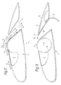
- Figure 2 illustrates diagrammatically an aerofoil or hydrofoil 1 which has a vessel 2 or other means of supplying pressurised fluid to a nozzle 3 so as to release a primary jet 4 of fluid over a convexly curved surface 5, not necessarily of circular section, the primary jet 4 eventually or directly attaching to the convex surface 5.
- the means for supplying pressurised fluid may be a fan, pump or other conventional fluid moving device.
- the convexly curved surface may include discontinuities (not shown) in order to encourage mixing between the primary jet and the ambient fluid 6 and in some applications it may be appropriate to rotate the convexly curved surface in order to control the direction of the attached jet at its furthest extremity.
- the convex surface 5 may be retracted partly or wholly into the aerofoil/hydrofoil main body 1 or otherwise closed in order not to impede the passage of the surrounding ambient flow.
- the profile of the convex surface is shaped so as to promote the efficient mixing of the primary jet and surrounding ambient fluid. It is the intention here that efficient mixing is promoted when there is an accompanying pressure reaction force from a solid boundary, which reaction force is substantially in line with the local flow direction which itself may be in the same or opposite sense to the flow direction. In this manner efficient mixing is achieved which results in an augmentation of thrust or lift force in the lift direction L and which can be accomplished within a relatively small increase in cross-sectional area between the exit of the primary jet and the section of the duct which delivers the mixed streams back to the ambient.
- An approach surface 7 on the aerofoil/hydrofoil guides part or all of the entrained ambient fluid 6 to the primary jet.
- This approach surface 7 may be made to move either linearly or rotationally by means (not shown) in order to form a smooth or near smooth tangential juncture with the upper region of the convexly curved surface 5 adjacent to or at its highest point, this movement being able to be performed preferably after the primary jet has been switched off.
- a duct 8 is provided rearwardly of the convex surface to direct some or all of the flow leaving the convexly curved surface 5 in a direction favourable to the resultant force required of the aerofoil/hydrofoil section.
- the cross-section of the duct 8 can be either constant or varying in the direction transverse to the majority of flow passing through it, but preferably the cross-sectional area increases slowly with flow direction as shown, as this is beneficial to the promotion of mixing between the primary jet and the entrained ambient fluid.
- the downstream end of this duct can have a system of guiding vanes to direct the release of the combined flow stream, thereby providing a further means of control of the direction of the resultant thrust.
- Figure 3 shows a diverter plate or plates 9,10 which may form one wall of the duct.
- the upper lip 11 of the aperture to the duct can be made to move generally in the direction M of the convexly curved surface (as indicated by the arrow in Figure 3) by either linear or rotational means (not shown) so that part or all of the combination of primary jet and entrained fluid can be redirected along the upper surface 12 of the downstream section of the aerofoil/hydrofoil.
- a diverter plate 13 may also be provided so as to deflect the exit stream from the duct in a direction so as to provide vectoring control of the resultant force. When not required, this diverter plate 13 may be retracted back into the main body of the aerofoil/hydrofoil by appropriate mechanical means such as a hydraulic ram (not shown). In certain applications, this plate may be orientated or constructed so as to cause an extreme deflection of the jet and thus provide a resultant force opposite the direction of motion of the vehicle, in other words, to perform thrust reversal.
- Figure 3 also shows how a circular cross-sectioned element 14 may be provided for rotation about a central axis A, whereby the convex surface 5 can be caused to rotate as described above.
Landscapes
- Engineering & Computer Science (AREA)
- Aviation & Aerospace Engineering (AREA)
- Wind Motors (AREA)
- Devices And Processes Conducted In The Presence Of Fluids And Solid Particles (AREA)
- Jet Pumps And Other Pumps (AREA)
- Turbine Rotor Nozzle Sealing (AREA)
Claims (6)
- Plan de sustentation ou plan aérodynamique comprenant :- une surface incurvée (5) convexe sur le côté du plan de sustentation ou plan aérodynamique qui se trouve dans la direction de la sustentation requise;- un moyen comportant une tuyère (3) pour fournir un jet primaire à haute vitesse (4) d'un fluide dirigé à partir de la tuyère (3) vers la surface convexe (5) de manière à entraîner un écoulement d'un fluide secondaire (6); et- une conduite (8) formée sur une partie arrière de la surface convexe (5) en aval de la tuyère (3); caractérisé en ce que :- la conduite (8) s'étend à partir de la surface convexe (5) en passant par le plan de sustentation ou plan aérodynamique jusqu'à la surface inférieure du plan de sustentation ou plan aérodynamique distante de la tuyère (3), d'où il résulte que le jet primaire (4) de fluide s'écoule à travers la surface convexe (5) et provoque la traversée de la conduite par un écoulement renforcé, la conduite étant dirigée au moins à son extrémité de sortie dans une direction telle que l'écoulement la traversant présente une composante de vitesse opposée à celle de la direction requise pour la sustentation.
- Plan de sustentation ou plan aérodynamique selon la revendication 1, dans lequel une surface non convexe est interposée entre la tuyère et la surface convexe.
- Plan de sustentation ou plan aérodynamique selon la revendication 1 ou la revendication 2, dans lequel on s'arrange pour que la résultante des forces agissant comme conséquence du jet primaire et du fluide secondaire entraîné soit sensiblement en alignement avec l'axe de la sustentation ou de la poussée requise.
- Plan de sustentation ou plan aérodynamique selon l'une quelconque des revendications 1 à 3, dans lequel la conduite est réglable de manière à diriger un écoulement de fluide vers elle soit dans une direction avec une composante de vitesse de même sens que la direction de déplacement du plan de sustentation ou plan aérodynamique, d'où la fourniture d'un moyen d'inversion de poussée, soit dans une direction avec une composante de vitesse de sens opposé à la direction du déplacement du plan de sustentation ou plan aérodynamique, d'où la fourniture d'un moyen pour augmenter la poussée.
- Plan de sustentation ou plan aérodynamique selon l'une quelconque des revendications 1 à 4, comprenant un moyen pour dévier le courant sortant de la conduite dans une direction permettant de fournir une commande vectorielle de la force résultante.
- Plan de sustentation ou plan aérodynamique selon l'une quelconque des revendications 1 à 5, dans lequel la surface convexe peut tourner autour d'un axe transversal au sens d'écoulement du courant du fluide passant sur son dessus.
Applications Claiming Priority (2)
| Application Number | Priority Date | Filing Date | Title |
|---|---|---|---|
| GB878713097A GB8713097D0 (en) | 1987-06-04 | 1987-06-04 | Aerofoil/hydrofoil |
| GB8713097 | 1987-06-04 |
Publications (2)
| Publication Number | Publication Date |
|---|---|
| EP0294145A1 EP0294145A1 (fr) | 1988-12-07 |
| EP0294145B1 true EP0294145B1 (fr) | 1992-12-02 |
Family
ID=10618370
Family Applications (1)
| Application Number | Title | Priority Date | Filing Date |
|---|---|---|---|
| EP88304938A Expired - Lifetime EP0294145B1 (fr) | 1987-06-04 | 1988-05-31 | Aile aéro-/hydrodynamique |
Country Status (5)
| Country | Link |
|---|---|
| US (1) | US4976349A (fr) |
| EP (1) | EP0294145B1 (fr) |
| CA (1) | CA1316516C (fr) |
| DE (1) | DE3876297T2 (fr) |
| GB (1) | GB8713097D0 (fr) |
Families Citing this family (30)
| Publication number | Priority date | Publication date | Assignee | Title |
|---|---|---|---|---|
| US5601047A (en) * | 1995-03-31 | 1997-02-11 | The United States Of America As Represented By The Secretary Of The Navy | Dualcavitating hydrofoil structures for multi-speed applications |
| US6045095A (en) * | 1998-09-23 | 2000-04-04 | Parrish, Iv; Overton L. | Vane-airfoil combination |
| US6457671B1 (en) * | 2001-09-05 | 2002-10-01 | Norman Sherman | Funneled rotary foil |
| US6905092B2 (en) | 2002-11-20 | 2005-06-14 | Airfoils, Incorporated | Laminar-flow airfoil |
| US7354247B2 (en) | 2005-10-27 | 2008-04-08 | General Electric Company | Blade for a rotor of a wind energy turbine |
| US7618086B2 (en) | 2005-12-01 | 2009-11-17 | Thomas Scott Breidenbach | Aerodynamic drag reducing apparatus |
| US8342594B2 (en) | 2007-01-16 | 2013-01-01 | Benton Craig R | Apparatus for reducing drag on a vehicle |
| US8360507B2 (en) * | 2007-01-16 | 2013-01-29 | Benton Craig R | Apparatus for reducing drag on a vehicle |
| US7862102B1 (en) | 2007-01-16 | 2011-01-04 | Benton Craig R | Apparatus for reducing drag on vehicles |
| US8360509B2 (en) | 2007-05-17 | 2013-01-29 | Advanced Transit Dynamics, Inc. | Rear-mounted aerodynamic structure for truck cargo bodies |
| US8100461B2 (en) | 2007-05-17 | 2012-01-24 | Advanced Transit Dynamics, Inc. | Rear-mounted aerodynamic structure for truck cargo bodies |
| US20110095564A1 (en) * | 2009-10-23 | 2011-04-28 | Chen Shih Hsiung | Nozzle-typed drag-reducing structure for vehicle |
| US8829706B1 (en) * | 2010-06-21 | 2014-09-09 | Johann Quincy Sammy | Adaptive control ducted compound wind turbine |
| FR2965591B1 (fr) * | 2010-09-30 | 2012-08-31 | Alstom Hydro France | Poutre de supportage d'un carenage d'hydrolienne et hydrolienne comportant une telle poutre |
| US20130076064A1 (en) | 2011-09-20 | 2013-03-28 | Advanced Transit Dynamics, Inc. | Rear-mounted retractable aerodynamic structure for cargo bodies |
| US9440689B1 (en) | 2011-09-20 | 2016-09-13 | Stemco Lp | Aerodynamic structures secured to the underbody of cargo bodies |
| CA2853727A1 (fr) | 2011-10-27 | 2013-05-02 | Advanced Transit Dynamics, Inc. | Structures aerodynamiques a montage arriere pour carrosseries pour marchandises |
| EP2872378A1 (fr) | 2012-07-11 | 2015-05-20 | Advanced Transit Dynamics, Inc. | Structures aérodynamiques rétractables pour corps de chargement et procédés permettant de commander le positionnement de celles-ci |
| US9630706B2 (en) * | 2013-02-22 | 2017-04-25 | Rolls-Royce Corporation | Positionable ejector member for ejector enhanced boundary layer alleviation |
| US10099771B2 (en) * | 2016-03-14 | 2018-10-16 | The Boeing Company | Aircraft wing structure and associated method for addressing lift and drag |
| US10669026B2 (en) | 2016-04-01 | 2020-06-02 | Albert Aguilar | Lift cell modules and lift pods |
| US10106246B2 (en) | 2016-06-10 | 2018-10-23 | Coflow Jet, LLC | Fluid systems that include a co-flow jet |
| US10315754B2 (en) | 2016-06-10 | 2019-06-11 | Coflow Jet, LLC | Fluid systems that include a co-flow jet |
| DE102017112742A1 (de) * | 2017-06-09 | 2018-12-13 | Wobben Properties Gmbh | Rotorblatt für eine Windenergieanlage und Windenergieanlage |
| US10683076B2 (en) | 2017-10-31 | 2020-06-16 | Coflow Jet, LLC | Fluid systems that include a co-flow jet |
| US11293293B2 (en) | 2018-01-22 | 2022-04-05 | Coflow Jet, LLC | Turbomachines that include a casing treatment |
| US11111025B2 (en) | 2018-06-22 | 2021-09-07 | Coflow Jet, LLC | Fluid systems that prevent the formation of ice |
| US11920617B2 (en) | 2019-07-23 | 2024-03-05 | Coflow Jet, LLC | Fluid systems and methods that address flow separation |
| US12202602B2 (en) | 2020-06-17 | 2025-01-21 | Coflow Jet, LLC | Fluid systems having a variable configuration |
| WO2022204278A1 (fr) | 2021-03-26 | 2022-09-29 | Coflow Jet, LLC | Pales d'éolienne et systèmes d'éolienne comprenant un jet à écoulement descendant |
Family Cites Families (12)
| Publication number | Priority date | Publication date | Assignee | Title |
|---|---|---|---|---|
| US1674169A (en) * | 1923-07-28 | 1928-06-19 | Inst Voor Aeroen Hydro Dynamie | Arrangement for exchanging energy between a current and a body therein |
| US1714609A (en) * | 1928-05-25 | 1929-05-28 | Henry P Massey | Airplane |
| GB616163A (en) * | 1943-01-19 | 1949-01-18 | Groupement Francais Pour Le Developpement Des Recherches Aeronautiques | Means for avoid separation and turbulence in fluids moving with respect to solid surfaces |
| FR927914A (fr) * | 1946-04-19 | 1947-11-13 | Constructions Aeronautiques Sudest | Procédé de contrôle des écoulements fluides autour des corps solides et dispositifs pour la mise en ceuvre de ce procédé |
| US2809793A (en) * | 1947-07-22 | 1957-10-15 | Douglas K Warner | High lift airfoil system |
| US3178131A (en) * | 1963-10-03 | 1965-04-13 | Laing Nikolaus | Aircraft wing structure |
| DE1951422A1 (de) * | 1969-10-11 | 1971-04-22 | Messerschmitt Boelkow Blohm | Tragfluegel mit Klappen zur Vor- und/oder Auftriebserzeugung |
| US3807663A (en) * | 1972-09-15 | 1974-04-30 | Ball Brothers Res Corp | Air foil structure |
| US4117995A (en) * | 1977-02-28 | 1978-10-03 | Runge Thomas M | Aircraft wing lift augmentation device |
| US4146197A (en) * | 1977-09-16 | 1979-03-27 | The United States Of America As Represented By The Secretary Of The Air Force | Boundary layer scoop for the enhancement of Coanda effect flow deflection over a wing/flap surface |
| US4285482A (en) * | 1979-08-10 | 1981-08-25 | The Boeing Company | Wing leading edge high lift device |
| US4848701A (en) * | 1987-06-22 | 1989-07-18 | Belloso Gregorio M | Vertical take-off and landing aircraft |
-
1987
- 1987-06-04 GB GB878713097A patent/GB8713097D0/en active Pending
-
1988
- 1988-05-31 DE DE8888304938T patent/DE3876297T2/de not_active Expired - Fee Related
- 1988-05-31 EP EP88304938A patent/EP0294145B1/fr not_active Expired - Lifetime
- 1988-06-01 CA CA000568363A patent/CA1316516C/fr not_active Expired - Fee Related
- 1988-06-02 US US07/201,177 patent/US4976349A/en not_active Expired - Fee Related
Also Published As
| Publication number | Publication date |
|---|---|
| CA1316516C (fr) | 1993-04-20 |
| DE3876297T2 (de) | 1993-04-01 |
| DE3876297D1 (de) | 1993-01-14 |
| US4976349A (en) | 1990-12-11 |
| GB8713097D0 (en) | 1987-07-08 |
| EP0294145A1 (fr) | 1988-12-07 |
Similar Documents
| Publication | Publication Date | Title |
|---|---|---|
| EP0294145B1 (fr) | Aile aéro-/hydrodynamique | |
| US3807663A (en) | Air foil structure | |
| US4200252A (en) | Helicopter antitorque system using circulation control | |
| US4174083A (en) | Flow deflector for fluid inlet | |
| US3815357A (en) | Thrust reversing apparatus | |
| KR100416176B1 (ko) | 경계층공기전환용변환숄더시스템및방법 | |
| US4047381A (en) | Gas turbine engine power plants for aircraft | |
| US7290738B1 (en) | Dual jet emerging lift augmentation system for airfoils and hydrofoils | |
| US2702986A (en) | Device for deflecting a fluid from its normal direction of flow | |
| JPS6339781B2 (fr) | ||
| US4587804A (en) | Device for increasing and deflecting thrust of jet-propulsion engine of V/STOL aircraft | |
| EP2979974B1 (fr) | Générateur de vortex immergé | |
| US4934632A (en) | Aerothermal ultra hypersonic aircraft | |
| US5297764A (en) | Air foil providing vortex attenuation | |
| US7124698B1 (en) | Auxiliary facilities for the maneuvering of submerged water jet propelled sea craft | |
| CA2009634C (fr) | Tuyeres segmentees orientables | |
| IL43401A (en) | Aircraft system lift ejector | |
| US5727381A (en) | Duct flow control system | |
| JP2022506861A (ja) | 適応型垂直離着陸推進システム | |
| US4387869A (en) | Mono-element combined supercritical high lift airfoil | |
| US4463920A (en) | Thrust deflector and force augmentor | |
| US4474350A (en) | Probe for water bomber | |
| US20050151016A1 (en) | Air discharge valve for an aircraft | |
| US4398687A (en) | Thrust deflector and force augmentor | |
| US5054720A (en) | Trapped vortex cavity |
Legal Events
| Date | Code | Title | Description |
|---|---|---|---|
| PUAI | Public reference made under article 153(3) epc to a published international application that has entered the european phase |
Free format text: ORIGINAL CODE: 0009012 |
|
| AK | Designated contracting states |
Kind code of ref document: A1 Designated state(s): DE FR GB IT |
|
| 17P | Request for examination filed |
Effective date: 19890525 |
|
| DIN1 | Information on inventor provided before grant (deleted) | ||
| RAP1 | Party data changed (applicant data changed or rights of an application transferred) |
Owner name: BRITISH AEROSPACE PLC |
|
| RIN1 | Information on inventor provided before grant (corrected) |
Inventor name: ADKINS, RICHARD CYRIL |
|
| RAP1 | Party data changed (applicant data changed or rights of an application transferred) |
Owner name: BRITISH AEROSPACE PLC |
|
| 17Q | First examination report despatched |
Effective date: 19900730 |
|
| RAP3 | Party data changed (applicant data changed or rights of an application transferred) |
Owner name: BRITISH AEROSPACE PLC |
|
| GRAA | (expected) grant |
Free format text: ORIGINAL CODE: 0009210 |
|
| AK | Designated contracting states |
Kind code of ref document: B1 Designated state(s): DE FR GB IT |
|
| ITF | It: translation for a ep patent filed | ||
| ET | Fr: translation filed | ||
| REF | Corresponds to: |
Ref document number: 3876297 Country of ref document: DE Date of ref document: 19930114 |
|
| PLBE | No opposition filed within time limit |
Free format text: ORIGINAL CODE: 0009261 |
|
| STAA | Information on the status of an ep patent application or granted ep patent |
Free format text: STATUS: NO OPPOSITION FILED WITHIN TIME LIMIT |
|
| 26N | No opposition filed | ||
| PGFP | Annual fee paid to national office [announced via postgrant information from national office to epo] |
Ref country code: FR Payment date: 19950410 Year of fee payment: 8 |
|
| PGFP | Annual fee paid to national office [announced via postgrant information from national office to epo] |
Ref country code: GB Payment date: 19950413 Year of fee payment: 8 |
|
| PGFP | Annual fee paid to national office [announced via postgrant information from national office to epo] |
Ref country code: DE Payment date: 19950421 Year of fee payment: 8 |
|
| PG25 | Lapsed in a contracting state [announced via postgrant information from national office to epo] |
Ref country code: GB Effective date: 19960531 |
|
| GBPC | Gb: european patent ceased through non-payment of renewal fee |
Effective date: 19960531 |
|
| PG25 | Lapsed in a contracting state [announced via postgrant information from national office to epo] |
Ref country code: FR Effective date: 19970131 |
|
| PG25 | Lapsed in a contracting state [announced via postgrant information from national office to epo] |
Ref country code: DE Effective date: 19970201 |
|
| REG | Reference to a national code |
Ref country code: FR Ref legal event code: ST |
|
| PG25 | Lapsed in a contracting state [announced via postgrant information from national office to epo] |
Ref country code: IT Free format text: LAPSE BECAUSE OF NON-PAYMENT OF DUE FEES Effective date: 20050531 |