EP0294164B1 - Amphibische Wohneinheit - Google Patents
Amphibische Wohneinheit Download PDFInfo
- Publication number
- EP0294164B1 EP0294164B1 EP19880304977 EP88304977A EP0294164B1 EP 0294164 B1 EP0294164 B1 EP 0294164B1 EP 19880304977 EP19880304977 EP 19880304977 EP 88304977 A EP88304977 A EP 88304977A EP 0294164 B1 EP0294164 B1 EP 0294164B1
- Authority
- EP
- European Patent Office
- Prior art keywords
- unit
- attitude
- hull
- guide means
- pivotal connection
- Prior art date
- Legal status (The legal status is an assumption and is not a legal conclusion. Google has not performed a legal analysis and makes no representation as to the accuracy of the status listed.)
- Expired - Lifetime
Links
Images


Classifications
-
- B—PERFORMING OPERATIONS; TRANSPORTING
- B60—VEHICLES IN GENERAL
- B60P—VEHICLES ADAPTED FOR LOAD TRANSPORTATION OR TO TRANSPORT, TO CARRY, OR TO COMPRISE SPECIAL LOADS OR OBJECTS
- B60P3/00—Vehicles adapted to transport, to carry or to comprise special loads or objects
- B60P3/32—Vehicles adapted to transport, to carry or to comprise special loads or objects comprising living accommodation for people, e.g. caravans, camping, or like vehicles
-
- B—PERFORMING OPERATIONS; TRANSPORTING
- B60—VEHICLES IN GENERAL
- B60F—VEHICLES FOR USE BOTH ON RAIL AND ON ROAD; VEHICLES CAPABLE OF TRAVELLING IN OR ON DIFFERENT MEDIA, e.g. AMPHIBIOUS VEHICLES
- B60F3/00—Amphibious vehicles, i.e. vehicles capable of travelling both on land and on water; Land vehicles capable of travelling under water
- B60F3/0061—Amphibious vehicles specially adapted for particular purposes or of a particular type
- B60F3/0092—Amphibious trailers
-
- B—PERFORMING OPERATIONS; TRANSPORTING
- B63—SHIPS OR OTHER WATERBORNE VESSELS; RELATED EQUIPMENT
- B63B—SHIPS OR OTHER WATERBORNE VESSELS; EQUIPMENT FOR SHIPPING
- B63B7/00—Collapsible, foldable, inflatable or like vessels
- B63B7/02—Collapsible, foldable, inflatable or like vessels comprising only rigid parts
- B63B7/04—Collapsible, foldable, inflatable or like vessels comprising only rigid parts sectionalised
-
- B—PERFORMING OPERATIONS; TRANSPORTING
- B63—SHIPS OR OTHER WATERBORNE VESSELS; RELATED EQUIPMENT
- B63B—SHIPS OR OTHER WATERBORNE VESSELS; EQUIPMENT FOR SHIPPING
- B63B35/00—Vessels or similar floating structures specially adapted for specific purposes and not otherwise provided for
- B63B35/44—Floating buildings, stores, drilling platforms, or workshops, e.g. carrying water-oil separating devices
- B63B2035/4426—Stationary floating buildings for human use, e.g. floating dwellings or floating restaurants
-
- Y—GENERAL TAGGING OF NEW TECHNOLOGICAL DEVELOPMENTS; GENERAL TAGGING OF CROSS-SECTIONAL TECHNOLOGIES SPANNING OVER SEVERAL SECTIONS OF THE IPC; TECHNICAL SUBJECTS COVERED BY FORMER USPC CROSS-REFERENCE ART COLLECTIONS [XRACs] AND DIGESTS
- Y02—TECHNOLOGIES OR APPLICATIONS FOR MITIGATION OR ADAPTATION AGAINST CLIMATE CHANGE
- Y02A—TECHNOLOGIES FOR ADAPTATION TO CLIMATE CHANGE
- Y02A30/00—Adapting or protecting infrastructure or their operation
Definitions
- THIS INVENTION relates to amphibious accommodation units and in particular to units which may be easily converted between a first attitude for use on land and a second attitude for use on water as specified in the preamble of claim 1, for example as disclosed in US-A-3 972 544.
- Caravans have become an increasingly popular vehicle for providing mobile accommodation for persons either for temporary accommodation for example for holiday purposes or the like or for permanent accommodation.
- houseboats are popular watercraft which, although usually only suitable for use in confined waterways, provide a considerable area of accommodation for persons again either on a temporary or permanent basis.
- Normally houseboats are only suited for use on water and caravans are only suited to use on land. Accordingly, if comparable accommodation provided by caravans and houseboats is required both on land and water, a person needs both forms of unit and although this can be achieved by hiring, it generally involves considerable expense.
- the present invention provides an amphibious accommodation unit comprising a first portion defining an accommodation area within said unit, said first portion including a first hull, a second portion defining a second hull, means interconnecting said first and second portions for pivotal movement about a transverse axis or axes extending abeam of said hulls, and means for pivotally moving said first and second portions relative to each other and for elevating and lowering said pivotal axis whereby to vary the position of pivotal movement of said first portion relative to said second portion so that said first and second portions may be moved between a first attitude wherein said second hull is longitudinally aligned with, to comprise an extension of said first hull so that said accommodation unit may be used on water and a second attitude wherein said second hull is moved away from alignment with said first hull.
- said second portion in said second attitude is disposed in a generally upright attitude adjacent to said first portion.
- said interconnecting means comprising guide means on one of said first or second portions and means movable along said guide means and defining a pivotal connection between said first and second portions and preferably said pivotal connection means is movable along said guide means during said raising or lowering of said second portion.
- said pivotal connection means is movable along said guide means towards and away from a position or positions therealong whereat said second portion is permitted to pivot about a said transverse axis towards and away from said first attitude.
- the guide means are suitably provided on opposite sides of said first portion and wherein said pivotal connection means comprise pivot members provided on said second portion.
- Each said guide means may comprise a hollow elongate member secured in an upright attitude to said first portion, with each said hollow member being longitudinally slotted and wherein each said pivot member has an enlarged head portion and a shank portion, said head portion being captive in said hollow member for movement therealong and wherein the shank portion of said pivot member projects through said longitudinal slot for engagement with said second portion.
- said pivotal connection means are located at the lower end of said guide means when said second portion is in said second attitude whilst in a second form said pivotal connection means are located at the upper end of said guide means when said second portion is in said second attitude.
- means are provided for releasably maintaining said pivotal connection means at said position or positions along said guide means.
- said moving means includes winch means mounted to said first portion and cable means extending from said winch means to said second portion, said winch means being operable to wind up said cable means and elevate said pivotal axis and said second portion from said second attitude until said pivotal connection means is moved to said position along said guide means and wherein said wind means is further operable to unwind said cable means whereby to permit said second portion to pivot about said transverse axis to said first attitude after said pivotal connection means is maintained at said position along said guide means by said releasable maintaining means.
- said winch means is further operable when said second portion is in said first attitude to wind up said cable means and cause said second portion to pivot about a said transverse axis to a substantially upright attitude and subsequently unwind said cable means to lower said pivotal axis and said second portion to said second attitude when said pivotal connection means is released from said position along said guide means.
- the cable means is preferably connected to opposite sides of said second portion and is guided transversely of said first portion.
- said first and second hulls include bulkheads, said bulkheads being juxtaposed when said second portion is in said first attitude and wherein said bulkheads include cut-out portions which mate when said second portion is disposed in said first attitude and which are disposed above the floating water level of said unit to define a passageway between said first and second portions.
- the unit may also include locking means for selectively locking said second hull in said first attitude.
- the first and second portions may also be provided with co-operative coupling means adapted to be releasable engaged to maintain said second portion in said second attitude and the coupling means are suitably moved out of register with each other when said second portion is moved away from said second attitude.
- the first and second hulls may also be provided with transversely extending complimentary recess and rib means adapted to co-operate when said second hull is in said first attitude.
- the unit may further include awning means adapted to be moved to a position overlying said second portion when the latter is in said first attitude.
- said first portion includes a roof
- guide means are provided on said roof to extend longitudinally of said unit, said awning means being guided for movement along said guide means between a first position overlying said roof and said position overlying said second portion.
- the unit is suitably braced by bracing means which brace said second portion against movement relative to said first portion when said second portion is in said first attitude.
- bracing means comprise railing means on opposite sides of said second portion, said railing means being pivotally movable to a first upright operative bracing position between said first portion and said second portion and a second folded inoperative position.
- the accommodation area is suitably defined by front and rear walls, a pair of opposite side walls and a roof and wherein said second portion in said second attitude extends substantially between said first hull and said roof of said accommodation area.
- the hulls may have any configuration desired such as mono-hull, catamaran, V-shape, trimaran, pontoon style or punt style.
- the unit 10 includes a first accommodation part 12 which is in the general form of a caravan type body having side walls 13, opposite end walls 14 and 15 and a top wall 16 and including a floatable hull 17 which in this embodiment is in the form of a catamaran type hull.
- the part 12 houses all the conventional appliances and furniture of a normal caravan such as bunks, stoves, fridges, tables or dinettes as well as W.C. and shower and as shown the side walls 11 and end wall 15 are fitted with windows and an external access door 18 is provided to enable access into the interior of part 11.
- a motor such as an outboard motor 19 is also fitted to the hull 17 via a conventional bracket 20 and controls for the motor such as a steering wheel, throttle etc. are located with the part 12 to enable the engine to be steered and controlled.
- a further hull 21 of open barge-like form which in the land use attitude shown in Fig. 1 is located in a substantially vertical attitude and nested neatly into the first part 12.
- the opposite side walls 13 of the first part are provided with extended flange portions 22 which are located on opposite sides of the hull 21 in the Fig. 1 attitude to prevent lateral movement thereof during road transportation.
- the bow of the hull 21 is raised at 23 to increase the seaworthyness of the unit 10 and the wall 15 of the part 12 is bevelled at 24 so that the hull 21 can neatly be engaged therewith.
- the hull 21 as more clearly shown in Fig. 5 is provided on opposite sides adjacent the gunwales with respective headed pivot pins 25, the heads 26 of which are located in and captive in vertical channel sectioned tracks 27 secured to the flange extensions 22 of the side walls 13 and the shanks 28 of the pins 25 project through elongated slots 29 in the tracks 27 into the hull 21 to define a pivot support therefor.
- the hull 21 and flanges 22 are also provided with co-operable restraining members 30 and 31 which are suitably in the form of opposite channel members which locate within each other when the hull 21 is in the Fig. 1 attitude to assist in maintaining the hull 21 in that attitude.
- the hull 21 is adapted to be moved from its position shown in Fig. 1 for land use to the position shown in Fig. 5 for water use by means of the winch and cable arrangement 32.
- This arrangement includes a hand operated winch 33 mounted to the side wall 13 and a winch cable 34 which extends from the winch 33 about a block 35 secured to the side wall flange 22, about a further block 36 secured to the hull 21 at intermediate position therealong and thence about a further block 37 supported on the flange 21 and about an adjacent fixed block 38 for passage preferably through a tube 39 to the opposite side of the first part 11 where the cable 34 passes about similar blocks 38′, 37′ and 36′ to be tied off by a shackle to a point on the wall flange 22 adjacent the block 37′.
- the winch 33 When it is desired to move the hull 21 to its operative position for use on water, the winch 33 is operated which will elevate the hull 21 from the position shown in Fig. 1 to that shown in Fig. 3 with the heads 26 of the respective pivot pins 25 during this movement moving along and within the tracks 27. Furthermore the co-operating channels 30 and 31 move during this time to a position wherein they are out of register with each other.
- lock pins 40 When the pivot pins 25 reach the upper ends of the tracks 27, lock pins 40 are inserted into respective aligned apertures 41 in opposite walls of the tracks 27 to prevent downward movement of the pivot pins 25.
- the winch 33 may then be reversed to slowly release the cable 34 so that the hull 21 will pivot away from the part 11 moving through the position shown in Fig.
- a pair of threaded locking bolts 42 are provided for passage through respective apertures 43 in the flanges 22 into threaded bores 44 in the hull 20 (see Fig. 5).
- the hull 21 is further supported in its operative attitude by respective pairs of railings 45 as more clearly shown in Figs. 4 and 6.
- the railings 45 comprise elongated rail members 46 which are connected to struts 47 pivotally connected at their lower ends to the hull 21 and pivotal from a folded attitude to an erected attitude wherein opposite ends of the rail members 46 are connected by bolting at 48 and 49 to the flanges 22 and raised hull portion 23.
- the part 11 also include an awning assembly 50 which includes a covered frame 51 slidably mounted in tracks 52 which extend along the top wall 16 (see Fig. 4).
- the awning assembly 50 may be extended out to the position shown in Figs. 4 and 6 and to support the free end of the assembly 50, a pair of support members 53 are provided, these members 53 being pivotally moveable from a inoperative position wherein they are held adjacent the frame 51 to the erected position of Figs. 4 and 6 wherein the lower ends of the members 53 are supported in sockets 54 on the hull 21.
- the members 53 are retained in position in their inoperative attitude by means of VELCRO type hook and loop material 55.
- the tracks 52 are of channel section form to slidably receive elongated members 56 of the frame 51.
- the respective mating hulls 21 and 17 are provided with cut-out portions 57 and 58 in their end bulkheads, the cut-out portions being disposed above the water level and defining a through passage between the hulls 17 and 21.
- the main part 12 is provided with a door 59 aligned with the respective cut-out portions as illustrated.
- a further hull 21′ as shown in dotted outline in Fig. 2 may also be provided at the end of the main part 12 opposite the hull 21 to be raised and lowered in a similar manner to that described above so that extended living space on water is provided for the unit 10.
- the hull 21 is provided with a transversely extending rib or moulding 60 and the hull 17 provided with a complimentary recess 61. It will be apparent that when the hull 21 is moved to the Fig. 4 and 6 position the rib 60 will rest within the recess 61 so as to substantially prevent water passing into the area between the mating bulkheads.
- the hull 21 may be provided with the recess 61 and the hull 17 with the complimentary rib 60.
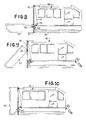
- Figs. 8 to 11 illustrate a further embodiment of the invention similar to that shown in Figs. 1 to 7 but arranged in this instance so that the hull 162 folds in an opposite direction against the main accommodation area 163
- the main area 163 is provided on opposite sides with full length guides or tracks 164 and the hull 162 is provided with opposite guide pins 165 which locate in the guides 164.
- the hull 162 constitutes an extension of the hull 166 of the main area 163 and is maintained in that attitude by further pins 167 which extend through the guides 164 into the hulls 162.
- the hull 162 is further supported in its extended position by means of triangular braces 168 pivotally connected to the main area 163 and moveable between an inoperative position alongside the side walls of the main area 163 and an operative position as shown in Fig. 24 where pins 169 are passed through the braces 168 into the hull 162 to brace the latter in use.
- a winch 170 is provided on the main area 163 and a cable 171 passes about a pulley 172 adjacent the upper end of the guide 164 and connects to the hull 162 adjacent the pins 165. It will be apparent from Figs. 25 and 26 that winding up of the winch 170 and thus cable 171 will elevate the end of the hull 162 adjacent the main area 163 until it lies in a generally vertical attitude adjacent the main area 163.
- the hull 162 may be restrained against sideways movement by means of the braces 168 which may be pivoted to the position of Fig. 26 and secured to the hull 162 if desired.
- the mating bulkheads of the hulls 162 and 166 may be providing with mating cut-out portions defining passageways between the hulls.
- rubber seals or seals of other material may be located between the bulkheads or alternatively flaps of flexible material may close over the join between the bulkheads.
- the units described above may be powered by outboard motor or alternatively inboard motors may be employed.
- the units according to the invention may be constructed of aluminium, timber or glass fibre such as fibreglass sandwich construction.
- the extended hull portions of the units considerably increase the living space of the unit when used in a water mode. Furthermore, if desired, open hull portions may be detached and used independently and if required motive power to such hulls may be provided by an outboard motor mounted over the cut out portion of the rear bulkhead.
- means other than the pin 40 may be provided for supporting the pivot pin 25 in its upper position.
- Such means may take the form of a triangle braces similar to that shown in Figs. 24 to 26 which will perform the dual function of supporting the pivot pins in the required position for folding and serving also to brace the folded hull after it has been moved to its extended position.
- a main accommodation area of the type 12 shown in Fig. 1 may be provided with different combinations of foldable hulls at each end of any of the above described forms.
Landscapes
- Engineering & Computer Science (AREA)
- Mechanical Engineering (AREA)
- Chemical & Material Sciences (AREA)
- Combustion & Propulsion (AREA)
- Transportation (AREA)
- Public Health (AREA)
- Health & Medical Sciences (AREA)
- Ocean & Marine Engineering (AREA)
- Tents Or Canopies (AREA)
- Polymers With Sulfur, Phosphorus Or Metals In The Main Chain (AREA)
- Accommodation For Nursing Or Treatment Tables (AREA)
- Filling Or Discharging Of Gas Storage Vessels (AREA)
- Management, Administration, Business Operations System, And Electronic Commerce (AREA)
- Helmets And Other Head Coverings (AREA)
- Coupling Device And Connection With Printed Circuit (AREA)
Claims (23)
- Amphibische Wohneinheit (10) mit einem ersten Abschnitt (12), der einen Wohnbereich innerhalb der Einheit (10) begrenzt, wobei der erste Abschnitt (12) einen ersten Rumpf (17) umfaßt, mit einem zweiten Abschnitt, der einen zweiten Rumpf (21) begrenzt, mit einem Mittel zur Verbindung der ersten und zweiten Abschnitte für eine Verschwenkbewegung um eine transversale Achse oder um Achsen, die querab zu den Rümpfen ausgerichtet sind, gekennzeichnet durch Mittel für eine Verschwenkbewegung der ersten und zweiten Abschnitte relativ zueinander und zum Anheben und zum Absenken der Schwenkachse, um die Lage der Verschwenkbewegung des ersten Abschnittes in Bezug auf den zweiten Abschnitt zu verändern, so daß die ersten und zweiten Abschnitte zwischen einer ersten Position, in der der zweite Rumpf (21) als eine Erweiterung des ersten Rumpfes (17) longitudinal ausgerichtet ist, so daß die Wohneinheit (10) auf dem Wasser eingesetzt werden kann, und einer zweiten Position bewegt werden können, bei der der zweite Rumpf (21) aus der Ausrichtung mit dem ersten Rumpf (17) wegbewegt ist.
- Einheit (10) nach Anspruch 1, bei der der zweite Abschnitt in der zweiten Position im wesentlichen in einer senkrechten Position benachbart zu dem ersten Abschnitt (12) angeordnet ist.
- Einheit (10) nach Anspruch 1 oder Anspruch 2, bei der das Verbindungsmittel über Führungsmittel (27) auf einer der ersten oder zweiten Abschnitte und über Mittel (25) verfügen, die entlang der Führungsmittel (27) bewegbar sind und eine verschwenkbare Verbindung zwischen den ersten und zweiten Abschnitten begrenzen.
- Einheit (10) nach Anspruch 3, bei der das verschwenkbare Verbindungsmittel (25) entlang der Führungsmittel (27) bewegbar ist, um die Schwenkachse während der Bewegung des ersten Abschnittes in Bezug auf den zweiten Abschnitt zu anzuheben oder abzusenken.
- Einheit (10) nach Anspruch 4, bei der das verschwenkbare Verbindungsmittel (25) entlang der Führungsmittel (27) auf eine Position oder auf Positionen zu oder von diesen weg entlang von diesen bewegt werden kann, wobei der zweite Abschnitt um eine transversale Achse in oder aus der ersten Position schwenkbar ist.
- Einheit (10) nach einem der Ansprüche 3 bis 5, bei der die Führungsmittel (27) auf gegenüberliegenden Seiten des ersten Abschnitts (12) vorgesehen sind und bei der das Schwenkverbindungsmittel (25) Verschwenkelemente umfaßt, die auf dem zweiten Abschnitt vorgesehen sind.
- Einheit (10) nach Anspruch 6, bei der jedes Führungsmittel ein hohles längliches Element (27) umfaßt, welches in einer aufrechten Position an dem ersten Abschnitt (12) befestigt ist, wobei jedes hohle Element (27) einen sich longitudinal erstreckenden Schlitz (29) aufweist, und bei der jedes Verschwenkelement über einen vergrößerten Kopfabschnitt (26) und über einen Schaftabschnitt (28) verfügt, wobei der Kopfabschnitt (26) in dem hohlen Element (27) zur Bewegung entlang von diesem aufnehmbar und festhaltbar ist, und bei der sich der Schaftabschnitt (28) des Verschwenkelementes für einen Eingriff in den zweiten Abschnitt durch den longitudinalen Schlitz (29) hindurch erstreckt.
- Einheit (10) nach einem der Ansprüche 5 bis 7, bei der das Schwenkverbindungsmittel (25) am unteren Ende der Führungsmittel (27) angeordnet ist, wenn sich der zweite Abschnitt in der zweiten Position befindet.
- Einheit (10) nach Anspruch 8, die ein Mittel (40,41) zum lösbaren Halten des Schwenkverbindungsmittels (25) in der Position oder in den Positionen entlang der Führungsmittel (27) aufweist.
- Einheit (10) nach einem der Ansprüche 3 bis 7, bei der das Schwenkverbindungsmittel (25) am oberen Ende der besagten Führungsmittel (27) angeordnet ist, wenn der zweite Abschnitt sich in der zweiten Position befindet.
- Einheit (10) nach Anspruch 9, bei der die Bewegungsmittel ein Windenmittel (33), das auf dem ersten Abschnitt (12) angeordnet ist und Kabelmittel (34) umfaßt, die sich von dem Windenmittel (33) aus zu dem zweiten Abschnitt hin erstrecken, wobei das Windenmittel (33) einsetzbar ist, um die Kabelmittel (34) aufzurollen und um die Schwenkachse und den zweiten Abschnitt aus der besagten zweiten Position anzuheben, bis das Schwenkverbindungsmittel (25) in eine besagte Position entlang der Führungsmittel (27) bewegt ist, und bei der das Windenmittel (33) weiter dazu vorgesehen ist, die Kabelmittel (34) abzurollen, um zu ermöglichen, daß der zweite Abschnitt um die besagte transversale Achse in die erste Position verschwenkt wird, nachdem das Schwenkverbindungsmittel (25) in der besagten Position entlang der Führungsmittel (27) durch lösbare Haltemittel (40,41) gehalten wird.
- Einheit (10) nach Anspruch 11, bei der das Windenmittel (33), wenn der zweite Abschnitt in der zweiten Position ist, weiter dazu einsetzbar ist, um die Kabelmittel (34) aufzurollen und um zu bewirken, daß der zweite Abschnitt um die transversale Achse in eine im wesentlichen aufrechte Lage verschwenkt wird, und um danach die Kabelmittel (34) abzurollen, um die Verschwenkachse abzusenken und den zweiten Abschnitt in die zweite Position zu bewegen, wenn das besagte Schwenkverbindungsmittel (25) aus der besagten Position entlang der Verbindungsmittel (27) gelöst worden ist.
- Einheit (10) nach Anspruch 11 oder Anspruch 12, bei der die Kabelmittel (34) mit gegenüberliegenden Seiten des zweiten Abschnittes verbunden und transversal zu dem ersten Abschnitt geführt sind.
- Einheit (10) nach einem der vorstehenden Ansprüche, bei der die ersten und zweiten Rümpfe (17,21) Schotte aufweisen, wobei die Schotte aneinander gelegt sind, wenn der zweite Abschnitt in der besagten ersten Position ist, und bei der die Schotte ausgeschnittene Abschnitte (57,58) aufweisen, die zusammenpassen, wenn der zweite Abschnitt in der ersten Position angeordnet ist, und die oberhalb des Wasserstandes der Einheit (10) angeordnet ist, um einen Übergang zwischen den ersten und zweiten Abschnitten zu gestatten.
- Einheit (10) nach einem der vorstehenden Ansprüche, die Verschlußmittel (42, 43, 44) zum selektiven Arretieren des zweiten Rumpfes in der ersten Position aufweisen.
- Einheit (10) nach einem der vorstehenden Ansprüche, bei der die ersten und zweiten Abschnitte mit zusammenwirkenden Kopplungsmitteln (30, 31) versehen sind, die geeignet sind, lösbar ineinander einzugreifen, um den zweiten Abschnitt in der zweiten Position zu halten.
- Einheit (10) nach Anspruch 16, bei der die zusammenwirkenden Kopplungsmittel (30, 31) aus dem Eingriff heraus auseinander bewegt sind, wenn der zweite Abschnitt aus der zweiten Position wegbewegt wird.
- Einheit (10) nach einem der vorstehenden Ansprüche, bei der der Wohnbereich durch Vorder- und Rückwände (14, 15), durch ein Paar von gegenüberliegenden Seitenwänden (13) und durch einem Dach begrenzt wird und bei der der zweite Abschnitt sich in der zweiten Position im wesentlichen zwischen dem ersten Rumpf und dem Dach des Wohnbereichs erstreckt.
- Einheit (10) nach einem der vorstehenden Ansprüche, bei der die ersten und zweiten Rümpfe (17, 21) mit transversal sich erstreckenden komplementären Ausnehmungen und Rippen versehen sind (61, 60), die geeignet sind, zusammenzuwirken, wenn sich der zweite Rumpf in der ersten Position befindet.
- Einheit (10) nach einem der vorstehenden Ansprüche, die über Abdeckmittel (50) verfügen, die geeignet sind, in eine Position bewegt zu werden, die den zweiten Abschnitt überdeckt, wenn sich dieser in der ersten Position befindet.
- Einheit (10) nach Anspruch 20, bei der der erste Abschnitt ein Dach, auf dem Dach angeordnete und sich entlang der Einheit (10) longitudinal erstreckende Führungsmittel (52) umfaßt, wobei die Abdeckmittel (50) zur Bewegung entlang der Führungsmittel (52) zwischen einer ersten, das Dach überdeckenden Position und der besagten, den zweiten Abschnitt überdeckenden Position geführt werden.
- Einheit (10) nach einem der vorstehenden Ansprüche, bei der Verankerungsmittel (45) vorgesehen sind, um den zweiten Abschnitt gegen eine Bewegung relativ zum ersten Abschnitt zu verankern, wenn sich der zweite Abschnitt in der ersten Position befindet.
- Einheit (10) nach Anspruch 21, bei der die Verankerungsmittel (45) Schienenmittel (46) auf gegenüberliegenden Seiten des zweiten Abschnittes umfassen, wobei diese Schienenmittel (46) schwenkbar in eine erste aufrecht stehende Verankerungsposition zwischen der ersten Position und der zweiten Position und in eine zweite gefaltete unwirksame Lage bewegbar sind.
Priority Applications (1)
| Application Number | Priority Date | Filing Date | Title |
|---|---|---|---|
| AT88304977T ATE89518T1 (de) | 1987-06-04 | 1988-06-01 | Amphibische wohneinheit. |
Applications Claiming Priority (14)
| Application Number | Priority Date | Filing Date | Title |
|---|---|---|---|
| AUPI230087 | 1987-06-04 | ||
| AU2300/87 | 1987-06-04 | ||
| AUPI267387 | 1987-06-24 | ||
| AU2673/87 | 1987-06-24 | ||
| AU3393/87 | 1987-07-29 | ||
| AUPI339387 | 1987-07-29 | ||
| AU3555/87 | 1987-08-05 | ||
| AUPI355587 | 1987-08-05 | ||
| AUPI425187 | 1987-09-09 | ||
| AU4251/87 | 1987-09-09 | ||
| AUPI454587 | 1987-09-24 | ||
| AU4545/87 | 1987-09-24 | ||
| AU6216/88 | 1988-01-08 | ||
| AUPI621688 | 1988-01-08 |
Publications (3)
| Publication Number | Publication Date |
|---|---|
| EP0294164A2 EP0294164A2 (de) | 1988-12-07 |
| EP0294164A3 EP0294164A3 (en) | 1989-05-24 |
| EP0294164B1 true EP0294164B1 (de) | 1993-05-19 |
Family
ID=27560711
Family Applications (1)
| Application Number | Title | Priority Date | Filing Date |
|---|---|---|---|
| EP19880304977 Expired - Lifetime EP0294164B1 (de) | 1987-06-04 | 1988-06-01 | Amphibische Wohneinheit |
Country Status (7)
| Country | Link |
|---|---|
| US (1) | US4869194A (de) |
| EP (1) | EP0294164B1 (de) |
| AT (1) | ATE89518T1 (de) |
| CA (1) | CA1332538C (de) |
| DE (1) | DE3881102T2 (de) |
| ES (1) | ES2041795T3 (de) |
| NZ (1) | NZ224828A (de) |
Families Citing this family (18)
| Publication number | Priority date | Publication date | Assignee | Title |
|---|---|---|---|---|
| US4981100A (en) * | 1989-12-18 | 1991-01-01 | Bergeron Jean Luc | House trailer and boat assembly |
| AU710698B2 (en) * | 1995-06-22 | 1999-09-30 | Arthur Donald Leigh | Recreational vehicle |
| US5642686A (en) * | 1995-12-22 | 1997-07-01 | Eagle Premier Ltd. | Collapsible boat |
| USD387325S (en) * | 1996-10-04 | 1997-12-09 | Daniel Joseph Deveau | Combined house boat and trailer |
| US6145465A (en) * | 1998-03-10 | 2000-11-14 | Murphree; Terry | Foldable camper/boat/trailer system and method |
| US6283057B1 (en) | 1999-01-08 | 2001-09-04 | United States Marine, Inc. | Boat with articulating bow and method for articulating the bow of a boat |
| USD438822S1 (en) | 1999-09-20 | 2001-03-13 | Salvatore S B Belcastro | Combined truck and boat |
| US6439145B1 (en) * | 2001-01-10 | 2002-08-27 | Donald L. Mensch | Convertible pontoon/camper/trailer construction |
| US6957990B2 (en) * | 2002-08-21 | 2005-10-25 | Lowe Jerry W | Electric houseboat |
| WO2005087580A1 (en) * | 2004-03-09 | 2005-09-22 | Alain Guigan | Multibarge |
| US20070056498A1 (en) * | 2005-09-12 | 2007-03-15 | Poser H Allan | Water vessel that includes a manufactured home on a floating section |
| SE529515C2 (sv) * | 2006-08-09 | 2007-09-04 | Alve Henricson | Anordning vid omändringsbar farkost |
| US7344182B1 (en) * | 2006-11-20 | 2008-03-18 | Girard Systems | Modular roof mount awning system |
| CN100542876C (zh) * | 2007-12-27 | 2009-09-23 | 马升昊 | 组合式多功能水陆交通运输工具 |
| US8539899B2 (en) | 2008-06-23 | 2013-09-24 | Getaway Concepts Pty Ltd | Multifunctional recreational vehicle |
| NZ587254A (en) | 2010-08-06 | 2011-11-25 | Stuart Michael Winterbourn | Mobile home with internal structure rotable from aligment with external surrounding structure to an extending configuration |
| USD704104S1 (en) | 2011-08-05 | 2014-05-06 | Matthew Bevan Wilkie | Mobile home |
| KR101660378B1 (ko) * | 2015-05-14 | 2016-09-27 | 노현기 | 수륙양용차량 |
Family Cites Families (9)
| Publication number | Priority date | Publication date | Assignee | Title |
|---|---|---|---|---|
| US1462800A (en) * | 1923-02-20 | 1923-07-24 | Julius N Clemmer | Foldable boat |
| US2659464A (en) * | 1949-03-16 | 1953-11-17 | George A Sweetman | Luggage carrier |
| US3090973A (en) * | 1959-11-19 | 1963-05-28 | Intercontinental Mfg Company I | Boats |
| US3199127A (en) * | 1963-01-31 | 1965-08-10 | Milford J Hunter | Amphibious vehicle |
| FR2079689A5 (de) * | 1970-02-10 | 1971-11-12 | Hir J P Le | |
| US3972544A (en) * | 1973-07-16 | 1976-08-03 | Olaf Soot | Amphibious camper including a retractable suspension system |
| DE3202885A1 (de) * | 1982-01-29 | 1983-08-11 | Siegfried 7000 Stuttgart Holzbaur | Klappboot |
| FR2523044A1 (fr) * | 1982-03-11 | 1983-09-16 | Ludinant Luc | Habitacle du type caravane transformable en bateau |
| US4716850A (en) * | 1986-12-24 | 1988-01-05 | Andre Lachance | Floatation assembly for off-road vehicle |
-
1988
- 1988-05-30 NZ NZ224828A patent/NZ224828A/xx unknown
- 1988-05-31 US US07/200,652 patent/US4869194A/en not_active Expired - Fee Related
- 1988-06-01 ES ES198888304977T patent/ES2041795T3/es not_active Expired - Lifetime
- 1988-06-01 CA CA000568320A patent/CA1332538C/en not_active Expired - Fee Related
- 1988-06-01 DE DE88304977T patent/DE3881102T2/de not_active Expired - Fee Related
- 1988-06-01 AT AT88304977T patent/ATE89518T1/de not_active IP Right Cessation
- 1988-06-01 EP EP19880304977 patent/EP0294164B1/de not_active Expired - Lifetime
Also Published As
| Publication number | Publication date |
|---|---|
| NZ224828A (en) | 1990-09-26 |
| CA1332538C (en) | 1994-10-18 |
| DE3881102T2 (de) | 1993-10-28 |
| ES2041795T3 (es) | 1993-12-01 |
| EP0294164A2 (de) | 1988-12-07 |
| EP0294164A3 (en) | 1989-05-24 |
| DE3881102D1 (de) | 1993-06-24 |
| ATE89518T1 (de) | 1993-06-15 |
| US4869194A (en) | 1989-09-26 |
Similar Documents
| Publication | Publication Date | Title |
|---|---|---|
| US4869194A (en) | Amphibious accommodation units | |
| US8454399B1 (en) | Amphibious vehicle | |
| US4522143A (en) | Folding boat with bow and stern sections | |
| US8539899B2 (en) | Multifunctional recreational vehicle | |
| US4048685A (en) | Trailable houseboat | |
| US5517940A (en) | Variable width multi-hulled boat with telescoping mast | |
| US6725796B2 (en) | Convertible pontoon/camper/trailer construction | |
| US3807338A (en) | Convertible trailer float and utility boat | |
| US6029598A (en) | Trailerable houseboat/camper with removable pontoons | |
| US4040134A (en) | Pontoon boat | |
| US3134991A (en) | Amphibious vehicles | |
| US5522339A (en) | Collapsible multi-hulled vessel | |
| US5688151A (en) | Collapsible boat powered by a land vehicle | |
| US3902441A (en) | Sailboat having retractable and self-ejectable hydraulic controls | |
| US20020033127A1 (en) | Mono hulled power boat convertible to twin or triple hulled operation | |
| US3792502A (en) | Amphibious vehicle | |
| US4024592A (en) | Camper-pontoon boat construction | |
| US4736702A (en) | Watercraft | |
| US3079616A (en) | Foldable floating platform | |
| US3199127A (en) | Amphibious vehicle | |
| DE2544435B2 (de) | Amphibienfahrzeug | |
| GB2135940A (en) | Semi-rigid inflatable boat | |
| US20190322334A1 (en) | A watercraft | |
| US2504256A (en) | Collapsible outboard motorboat | |
| WO1984002504A1 (en) | Watercraft towing and floatation deck apparatus |
Legal Events
| Date | Code | Title | Description |
|---|---|---|---|
| PUAI | Public reference made under article 153(3) epc to a published international application that has entered the european phase |
Free format text: ORIGINAL CODE: 0009012 |
|
| AK | Designated contracting states |
Kind code of ref document: A2 Designated state(s): AT BE CH DE ES FR GB GR IT LI LU NL SE |
|
| PUAL | Search report despatched |
Free format text: ORIGINAL CODE: 0009013 |
|
| AK | Designated contracting states |
Kind code of ref document: A3 Designated state(s): AT BE CH DE ES FR GB GR IT LI LU NL SE |
|
| 17P | Request for examination filed |
Effective date: 19891104 |
|
| 17Q | First examination report despatched |
Effective date: 19911205 |
|
| GRAA | (expected) grant |
Free format text: ORIGINAL CODE: 0009210 |
|
| AK | Designated contracting states |
Kind code of ref document: B1 Designated state(s): AT BE CH DE ES FR GB GR IT LI LU NL SE |
|
| PG25 | Lapsed in a contracting state [announced via postgrant information from national office to epo] |
Ref country code: SE Effective date: 19930519 Ref country code: LI Effective date: 19930519 Ref country code: GR Free format text: LAPSE BECAUSE OF FAILURE TO SUBMIT A TRANSLATION OF THE DESCRIPTION OR TO PAY THE FEE WITHIN THE PRESCRIBED TIME-LIMIT Effective date: 19930519 Ref country code: CH Effective date: 19930519 Ref country code: AT Effective date: 19930519 |
|
| REF | Corresponds to: |
Ref document number: 89518 Country of ref document: AT Date of ref document: 19930615 Kind code of ref document: T |
|
| ITF | It: translation for a ep patent filed | ||
| RAP4 | Party data changed (patent owner data changed or rights of a patent transferred) |
Owner name: CUMMINS, IAN GEOFFREY |
|
| REF | Corresponds to: |
Ref document number: 3881102 Country of ref document: DE Date of ref document: 19930624 |
|
| PG25 | Lapsed in a contracting state [announced via postgrant information from national office to epo] |
Ref country code: LU Free format text: LAPSE BECAUSE OF NON-PAYMENT OF DUE FEES Effective date: 19930630 |
|
| ET | Fr: translation filed | ||
| REG | Reference to a national code |
Ref country code: CH Ref legal event code: PL |
|
| REG | Reference to a national code |
Ref country code: ES Ref legal event code: FG2A Ref document number: 2041795 Country of ref document: ES Kind code of ref document: T3 |
|
| PLBE | No opposition filed within time limit |
Free format text: ORIGINAL CODE: 0009261 |
|
| STAA | Information on the status of an ep patent application or granted ep patent |
Free format text: STATUS: NO OPPOSITION FILED WITHIN TIME LIMIT |
|
| 26N | No opposition filed | ||
| PGFP | Annual fee paid to national office [announced via postgrant information from national office to epo] |
Ref country code: GB Payment date: 19960426 Year of fee payment: 9 |
|
| PGFP | Annual fee paid to national office [announced via postgrant information from national office to epo] |
Ref country code: FR Payment date: 19960607 Year of fee payment: 9 |
|
| PGFP | Annual fee paid to national office [announced via postgrant information from national office to epo] |
Ref country code: ES Payment date: 19960617 Year of fee payment: 9 |
|
| PGFP | Annual fee paid to national office [announced via postgrant information from national office to epo] |
Ref country code: NL Payment date: 19960620 Year of fee payment: 9 |
|
| PGFP | Annual fee paid to national office [announced via postgrant information from national office to epo] |
Ref country code: DE Payment date: 19960626 Year of fee payment: 9 |
|
| PGFP | Annual fee paid to national office [announced via postgrant information from national office to epo] |
Ref country code: BE Payment date: 19960701 Year of fee payment: 9 |
|
| PG25 | Lapsed in a contracting state [announced via postgrant information from national office to epo] |
Ref country code: GB Effective date: 19970601 |
|
| PG25 | Lapsed in a contracting state [announced via postgrant information from national office to epo] |
Ref country code: ES Free format text: LAPSE BECAUSE OF EXPIRATION OF PROTECTION Effective date: 19970602 |
|
| PG25 | Lapsed in a contracting state [announced via postgrant information from national office to epo] |
Ref country code: BE Effective date: 19970630 |
|
| BERE | Be: lapsed |
Owner name: CUMMINS IAN GEOFFREY Effective date: 19970630 |
|
| PG25 | Lapsed in a contracting state [announced via postgrant information from national office to epo] |
Ref country code: NL Effective date: 19980101 |
|
| GBPC | Gb: european patent ceased through non-payment of renewal fee |
Effective date: 19970601 |
|
| PG25 | Lapsed in a contracting state [announced via postgrant information from national office to epo] |
Ref country code: FR Free format text: LAPSE BECAUSE OF NON-PAYMENT OF DUE FEES Effective date: 19980227 |
|
| NLV4 | Nl: lapsed or anulled due to non-payment of the annual fee |
Effective date: 19980101 |
|
| PG25 | Lapsed in a contracting state [announced via postgrant information from national office to epo] |
Ref country code: DE Free format text: LAPSE BECAUSE OF NON-PAYMENT OF DUE FEES Effective date: 19980303 |
|
| REG | Reference to a national code |
Ref country code: FR Ref legal event code: ST |
|
| REG | Reference to a national code |
Ref country code: FR Ref legal event code: ST |
|
| REG | Reference to a national code |
Ref country code: ES Ref legal event code: FD2A Effective date: 20000301 |
|
| PG25 | Lapsed in a contracting state [announced via postgrant information from national office to epo] |
Ref country code: IT Free format text: LAPSE BECAUSE OF NON-PAYMENT OF DUE FEES;WARNING: LAPSES OF ITALIAN PATENTS WITH EFFECTIVE DATE BEFORE 2007 MAY HAVE OCCURRED AT ANY TIME BEFORE 2007. THE CORRECT EFFECTIVE DATE MAY BE DIFFERENT FROM THE ONE RECORDED. Effective date: 20050601 |