EP0294286A2 - Scheibenbremsenfeder und mit einer solchen Feder ausgerüstete Scheibenbremse - Google Patents
Scheibenbremsenfeder und mit einer solchen Feder ausgerüstete Scheibenbremse Download PDFInfo
- Publication number
- EP0294286A2 EP0294286A2 EP88401323A EP88401323A EP0294286A2 EP 0294286 A2 EP0294286 A2 EP 0294286A2 EP 88401323 A EP88401323 A EP 88401323A EP 88401323 A EP88401323 A EP 88401323A EP 0294286 A2 EP0294286 A2 EP 0294286A2
- Authority
- EP
- European Patent Office
- Prior art keywords
- spring
- brake
- rigid
- friction members
- disc
- Prior art date
- Legal status (The legal status is an assumption and is not a legal conclusion. Google has not performed a legal analysis and makes no representation as to the accuracy of the status listed.)
- Granted
Links
Images

Classifications
-
- F—MECHANICAL ENGINEERING; LIGHTING; HEATING; WEAPONS; BLASTING
- F16—ENGINEERING ELEMENTS AND UNITS; GENERAL MEASURES FOR PRODUCING AND MAINTAINING EFFECTIVE FUNCTIONING OF MACHINES OR INSTALLATIONS; THERMAL INSULATION IN GENERAL
- F16D—COUPLINGS FOR TRANSMITTING ROTATION; CLUTCHES; BRAKES
- F16D55/00—Brakes with substantially-radial braking surfaces pressed together in axial direction, e.g. disc brakes
- F16D55/02—Brakes with substantially-radial braking surfaces pressed together in axial direction, e.g. disc brakes with axially-movable discs or pads pressed against axially-located rotating members
-
- F—MECHANICAL ENGINEERING; LIGHTING; HEATING; WEAPONS; BLASTING
- F16—ENGINEERING ELEMENTS AND UNITS; GENERAL MEASURES FOR PRODUCING AND MAINTAINING EFFECTIVE FUNCTIONING OF MACHINES OR INSTALLATIONS; THERMAL INSULATION IN GENERAL
- F16D—COUPLINGS FOR TRANSMITTING ROTATION; CLUTCHES; BRAKES
- F16D55/00—Brakes with substantially-radial braking surfaces pressed together in axial direction, e.g. disc brakes
- F16D55/02—Brakes with substantially-radial braking surfaces pressed together in axial direction, e.g. disc brakes with axially-movable discs or pads pressed against axially-located rotating members
- F16D55/22—Brakes with substantially-radial braking surfaces pressed together in axial direction, e.g. disc brakes with axially-movable discs or pads pressed against axially-located rotating members by clamping an axially-located rotating disc between movable braking members, e.g. movable brake discs or brake pads
- F16D55/224—Brakes with substantially-radial braking surfaces pressed together in axial direction, e.g. disc brakes with axially-movable discs or pads pressed against axially-located rotating members by clamping an axially-located rotating disc between movable braking members, e.g. movable brake discs or brake pads with a common actuating member for the braking members
- F16D55/225—Brakes with substantially-radial braking surfaces pressed together in axial direction, e.g. disc brakes with axially-movable discs or pads pressed against axially-located rotating members by clamping an axially-located rotating disc between movable braking members, e.g. movable brake discs or brake pads with a common actuating member for the braking members the braking members being brake pads
- F16D55/226—Brakes with substantially-radial braking surfaces pressed together in axial direction, e.g. disc brakes with axially-movable discs or pads pressed against axially-located rotating members by clamping an axially-located rotating disc between movable braking members, e.g. movable brake discs or brake pads with a common actuating member for the braking members the braking members being brake pads in which the common actuating member is moved axially, e.g. floating caliper disc brakes
- F16D55/2265—Brakes with substantially-radial braking surfaces pressed together in axial direction, e.g. disc brakes with axially-movable discs or pads pressed against axially-located rotating members by clamping an axially-located rotating disc between movable braking members, e.g. movable brake discs or brake pads with a common actuating member for the braking members the braking members being brake pads in which the common actuating member is moved axially, e.g. floating caliper disc brakes the axial movement being guided by one or more pins engaging bores in the brake support or the brake housing
- F16D55/227—Brakes with substantially-radial braking surfaces pressed together in axial direction, e.g. disc brakes with axially-movable discs or pads pressed against axially-located rotating members by clamping an axially-located rotating disc between movable braking members, e.g. movable brake discs or brake pads with a common actuating member for the braking members the braking members being brake pads in which the common actuating member is moved axially, e.g. floating caliper disc brakes the axial movement being guided by one or more pins engaging bores in the brake support or the brake housing by two or more pins
-
- F—MECHANICAL ENGINEERING; LIGHTING; HEATING; WEAPONS; BLASTING
- F16—ENGINEERING ELEMENTS AND UNITS; GENERAL MEASURES FOR PRODUCING AND MAINTAINING EFFECTIVE FUNCTIONING OF MACHINES OR INSTALLATIONS; THERMAL INSULATION IN GENERAL
- F16D—COUPLINGS FOR TRANSMITTING ROTATION; CLUTCHES; BRAKES
- F16D55/00—Brakes with substantially-radial braking surfaces pressed together in axial direction, e.g. disc brakes
- F16D55/02—Brakes with substantially-radial braking surfaces pressed together in axial direction, e.g. disc brakes with axially-movable discs or pads pressed against axially-located rotating members
- F16D55/22—Brakes with substantially-radial braking surfaces pressed together in axial direction, e.g. disc brakes with axially-movable discs or pads pressed against axially-located rotating members by clamping an axially-located rotating disc between movable braking members, e.g. movable brake discs or brake pads
- F16D55/224—Brakes with substantially-radial braking surfaces pressed together in axial direction, e.g. disc brakes with axially-movable discs or pads pressed against axially-located rotating members by clamping an axially-located rotating disc between movable braking members, e.g. movable brake discs or brake pads with a common actuating member for the braking members
- F16D55/225—Brakes with substantially-radial braking surfaces pressed together in axial direction, e.g. disc brakes with axially-movable discs or pads pressed against axially-located rotating members by clamping an axially-located rotating disc between movable braking members, e.g. movable brake discs or brake pads with a common actuating member for the braking members the braking members being brake pads
- F16D55/226—Brakes with substantially-radial braking surfaces pressed together in axial direction, e.g. disc brakes with axially-movable discs or pads pressed against axially-located rotating members by clamping an axially-located rotating disc between movable braking members, e.g. movable brake discs or brake pads with a common actuating member for the braking members the braking members being brake pads in which the common actuating member is moved axially, e.g. floating caliper disc brakes
-
- F—MECHANICAL ENGINEERING; LIGHTING; HEATING; WEAPONS; BLASTING
- F16—ENGINEERING ELEMENTS AND UNITS; GENERAL MEASURES FOR PRODUCING AND MAINTAINING EFFECTIVE FUNCTIONING OF MACHINES OR INSTALLATIONS; THERMAL INSULATION IN GENERAL
- F16D—COUPLINGS FOR TRANSMITTING ROTATION; CLUTCHES; BRAKES
- F16D65/00—Parts or details
- F16D65/02—Braking members; Mounting thereof
- F16D65/04—Bands, shoes or pads; Pivots or supporting members therefor
- F16D65/092—Bands, shoes or pads; Pivots or supporting members therefor for axially-engaging brakes, e.g. disc brakes
- F16D65/095—Pivots or supporting members therefor
- F16D65/097—Resilient means interposed between pads and supporting members or other brake parts
- F16D65/0973—Resilient means interposed between pads and supporting members or other brake parts not subjected to brake forces
- F16D65/0974—Resilient means interposed between pads and supporting members or other brake parts not subjected to brake forces acting on or in the vicinity of the pad rim in a direction substantially transverse to the brake disc axis
- F16D65/0977—Springs made from sheet metal
Definitions
- the subject of the invention is a spring for a disc brake with a sliding caliper and a disc brake equipped with such a spring.
- the invention relates more particularly to a spring intended to equip a disc brake whose caliper slides with respect to a fixed support by means of at least two complementary axial sliding surfaces formed on the caliper and on the fixed support and which are kept in contact by elastic means.
- French patent 2,582,365 discloses a spring for a disc brake of the type comprising a caliper mounted to slide parallel to the axis of a rotating disc, on a fixed support by means of at least two axial sliding surfaces formed on the caliper and on the fixed support and held elastically in contact, and two friction members received in anchoring and in axial sliding in an opening of said fixed support to come into friction engagement with the opposite faces of said disc, during actuation of 'a brake motor, said spring being resiliently mounted in an opening formed in the arch of the caliper and exerting on the support plates of said friction members, a radial force directed substantially along a radius of the disc and towards the axis of the latter, and a tangential force perpendicular to said radial force to urge each of the friction members tangentially to the circumference of said disc to ensure the maintenance of these d last in a preferred lateral position.
- This spring is characterized in that it consists of a folded metal blade comprising a mounting portion connected elastically by its circumferentially spaced sides to two portions of rigid action, a first rigid portion extending parallel to the axis of the disc and capable of urging elastically by its two free ends of said support plates in a substantially circumferential direction, a second said rigid portions also extending parallel to the axis of the disc and capable of urging elastically by its two free ends said support plates substantially radially towards the axis of the disc.
- Each rigid portion of the spring described in the aforementioned patent has two free ends, each of which rests on a support plate associated with a friction member.
- the progressive wear thereof has the effect of bringing it closer to the median plane of the brake spring, which moves the contact area of the rigid portion with the support plate, from a free end of the rigid portion towards the middle part of it.
- This middle part is connected to the associated elastic portion of the spring according to a profile which gives the rigid part an increasing width, along the axis of the disc, from a free end towards the middle part of the rigid part.
- the greater width of this part has the effect of locally increasing its stiffness.
- the object of the present invention is therefore to produce a spring for a disc brake, of the type described in the aforementioned patent, which does not have the drawbacks mentioned above.
- a spring for a disc brake of the type comprising a caliper mounted slidingly parallel to the axis of a disc rotating on a fixed support and two friction members received in anchoring and in axial sliding in a opening of said fixed support, to come into friction engagement with the opposite faces of the disc when actuating a brake motor, said spring being resiliently mounted in an opening formed in the arch of the caliper, to load each of the friction members, this spring consisting of a folded metal blade comprising a mounting portion connected by an elastic portion to at least one rigid action portion extending parallel to the axis of the disc to elastically urge said friction members , spring characterized in that a transverse slot parallel to the rigid portion is cut in the elastic portion near this rigid portion, so as to reduce the load applied ée by the spring to the friction members when these approach the median plane of the spring due to the wear of these members.
- the invention provides a spring for a disc brake of the type comprising a caliper mounted slidingly parallel to the axis. of a disc rotating on a fixed support and two friction members received in anchoring and sliding in an opening of said fixed support, to come into friction engagement with the opposite faces of said disc during the actuation of a brake motor , said spring being resiliently mounted in an opening formed in the arch of the stirrup to load each of the friction members, this spring consisting of a folded metal blade comprising a mounting portion connected by an elastic portion to a portion of rigid action extending parallel to the axis of the disc to elastically urge said friction members, this spring being characterized in that a tab projects beyond the rigid action portion so that, when the friction members are removed from the brake, this tab abuts elastically on a surface of the brake arranged to keep the rigid portion away from contact with a fragile part of the brake.
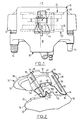
- the disc brake shown in FIG. 1 is of the type comprising a caliper 10, slidably mounted on a fixed support 12, by means of two axial columns 14 and 15.
- the disc brake further comprises two friction members 22 and 24, provided with support plates 26 and 28 respectively, capable of coming into friction engagement with a rotating disc 30, (see Figs. 3 and 4), when a hydraulic brake motor 32 is actuated.
- the friction members 22 and 24 are received in anchoring and sliding in an opening formed in the fixed support 12.
- the two friction members 22 and 24 each have ends 36 and 38 having a circular profile cooperating with circular profiles complementary to the fixed support 12.
- Such a type of friction member is described and shown in more detail in European patent EP-AO 002 399.
- the disc brake shown in Figure 1 is provided with a spring 40 made according to the present invention.
- the spring 40 consists of a folded metal blade which comprises a mounting portion 42 having the general shape of the Greek letter omega elastically mounted in an opening 44 formed in the arch of the stirrup 10.
- the circumferentially spaced sides 46 and 48 forming the constricted parts of the omega letter cooperate with circumferentially spaced edges 50 and 52 of the opening 44.
- the circumferentially spaced sides 46 and 48 are extended by elastic portions 54 and 56 respectively.
- These elastic portions 54 and 56 end in two rigid portions 58 and 60 which extend axially on either side of the corresponding elastic portion 54 or 56 respectively.
- a first rigid portion 58 associated with the elastic portion 54 has two free ends 62, 64 which stress each of the support plates 26, 28 substantially circumferentially (see FIG. 5), by cooperation with bearing surfaces 66 formed on the side d 'a projection 68 formed on the peripheral side 70 of each of the support plates 26 and 28.
- the rigid portion 58 has the shape of a gutter, the corresponding elastic portion 54 forming a pronounced rounded fold 72 (see FIG. 5) so as to allow the rigid portion 58 to urge the projection 68 outside the area occupied by the friction members and by the disc.
- the rigid portion 60 has the shape of a gutter and has two free ends 74 and 76 which cooperate with substantially circumferential bearing surfaces 80 formed on the peripheral side 70 of the support plates 26 and 28.
- the first rigid portion 58 thanks to the fold 72, exerts on the surface 66 a substantially tangential force T.
- the second rigid portion 60 exerts on the surface 80, a substantially radial force R.
- transverse slots 90, 92 formed in the vicinity of the rigid portions 58, 60, respectively, of the side of the elastic portions 54,56, respectively (see Figure 2).
- These slots have the effect of reducing the stiffness of the spring in its central part, in line with the elastic portions 54 and 56.
- the forces applied to the support plates 26, 28 by the spring when the friction members approach the median plane of the spring , as they wear out, are then reduced compared to the forces which would be applied in the absence of these slots. This reduction in effort makes it possible to avoid the drawbacks mentioned above.
- a tab 100 projects laterally and vertically from one end of the rigid portion 58 of the spring. With reference to FIGS. 3 and 4 of the drawing, it is clear that this tab projects beyond the spring on the side where the brake motor 32 is located.
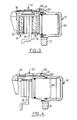
- the brake motor shown in section in Figs 3 and 4 comprises a piston 102 arranged to act on the support plate 26 of the friction member 22, during braking.
- a cap 103 made of flexible material seals the cylinder of the engine 32 which receives the piston, when the latter slides in the cylinder during braking.
- the disc brake is shown without its friction members, the piston extended and the cap 103 deployed, as is the case when the brake is replaced to replace worn friction members.
- the rigid portion 58 of the spring 40 is no longer pushed up by the support plates on which it rested before the extraction of the friction members.
- the rigid portion 58 can then come to bear accidentally on the cap 103 at the risk of shearing the latter due to the fact that it is made of a frangible material such as synthetic rubber.
- the tab 100 makes it possible to avoid this accident. It appears in fact in FIG. 4 and in FIG. 5 (position marked in broken lines) that in the absence of friction members, the lug comes to rest on the upper surface 101 of the brake motor, thereby maintaining the portion rigid 58 of the spring away from the cap 103 of the brake motor.
- the tab 100 and the slot 90 are formed on either side of the rigid portion 58.
- the tab first projects vertically (from the point of view of FIG. 2) from this rigid portion by a substantially radial connecting part 104, from the upper part of which extends the flat and horizontal end of the tab 100 proper, which projects laterally from the support plate 26 towards the upper surface 101 of the brake motor 32.
- Figure 6 is similar to Figure 5 and shows another embodiment of the spring according to the invention. This differs from that of FIG. 5 in that it is simplified by the elimination of the elastic portion 56 and of the rigid portion 60 which applies, in the embodiment of FIG. 5, substantially radial forces to the support plates. The elimination of these forces can indeed be considered acceptable with a certain orientation of the force applied by the other rigid portion of the spring on the bearing surface 66 modified accordingly.
- the removal of this part 56, 60 of the spring makes it possible to reduce the housing 105 hollowed out in the arch of the stirrup 10 (see Figure 5) to allow the movement of this part.
- the arch 10 of the caliper is then hollowed out with a smaller housing 105 ′, which has the effect of improving the robustness of the brake equipped with the spring according to the invention.
Landscapes
- Engineering & Computer Science (AREA)
- General Engineering & Computer Science (AREA)
- Mechanical Engineering (AREA)
- Braking Arrangements (AREA)
Applications Claiming Priority (2)
| Application Number | Priority Date | Filing Date | Title |
|---|---|---|---|
| FR8707677A FR2616186B1 (fr) | 1987-06-02 | 1987-06-02 | Ressort pour frein a disque et frein a disque equipe d'un tel ressort |
| FR8707677 | 1987-06-02 |
Related Child Applications (1)
| Application Number | Title | Priority Date | Filing Date |
|---|---|---|---|
| EP89202698.0 Division-Into | 1989-10-26 |
Publications (3)
| Publication Number | Publication Date |
|---|---|
| EP0294286A2 true EP0294286A2 (de) | 1988-12-07 |
| EP0294286A3 EP0294286A3 (en) | 1989-01-11 |
| EP0294286B1 EP0294286B1 (de) | 1991-04-24 |
Family
ID=9351654
Family Applications (2)
| Application Number | Title | Priority Date | Filing Date |
|---|---|---|---|
| EP88401323A Expired - Lifetime EP0294286B1 (de) | 1987-06-02 | 1988-05-31 | Scheibenbremsenfeder und mit einer solchen Feder ausgerüstete Scheibenbremse |
| EP89202698A Expired - Lifetime EP0355936B1 (de) | 1987-06-02 | 1988-05-31 | Scheibenbremsenfeder und mit einer solchen Feder ausgerüstete Scheibenbremse |
Family Applications After (1)
| Application Number | Title | Priority Date | Filing Date |
|---|---|---|---|
| EP89202698A Expired - Lifetime EP0355936B1 (de) | 1987-06-02 | 1988-05-31 | Scheibenbremsenfeder und mit einer solchen Feder ausgerüstete Scheibenbremse |
Country Status (8)
| Country | Link |
|---|---|
| US (1) | US5002161A (de) |
| EP (2) | EP0294286B1 (de) |
| JP (1) | JPS63312526A (de) |
| KR (1) | KR950013934B1 (de) |
| DE (2) | DE3866353D1 (de) |
| DK (2) | DK166164C (de) |
| ES (2) | ES2022657B3 (de) |
| FR (1) | FR2616186B1 (de) |
Cited By (2)
| Publication number | Priority date | Publication date | Assignee | Title |
|---|---|---|---|---|
| WO1991005176A1 (de) * | 1989-10-06 | 1991-04-18 | Alfred Teves Gmbh | Teilbelag-scheibenbremse |
| EP0501534A1 (de) * | 1991-02-02 | 1992-09-02 | Acg France | Antiratterfeder für Scheibenbremse |
Families Citing this family (6)
| Publication number | Priority date | Publication date | Assignee | Title |
|---|---|---|---|---|
| FR2635842B1 (fr) * | 1988-08-29 | 1990-10-19 | Bendix France | Ressort pour frein a disque et frein a disque le comportant |
| US5358079A (en) * | 1993-09-21 | 1994-10-25 | Alliedsignal Inc. | Disc brake with friction pad backing plate biasing spring |
| EP1898114B1 (de) * | 2006-09-02 | 2009-02-11 | BPW Bergische Achsen KG | Bremsbelag für Fahrzeug-Scheibenbremsen |
| JP4730692B2 (ja) * | 2007-02-28 | 2011-07-20 | 曙ブレーキ工業株式会社 | ディスクブレーキ装置用パッドスプリング |
| DE102016004516A1 (de) * | 2016-04-13 | 2017-10-19 | Wabco Europe Bvba | Scheibenbremse, insbesondere für Nutzfahrzeuge |
| CN111306221A (zh) * | 2020-03-31 | 2020-06-19 | 张建平 | 一种具有定制固定卡扣的卡钳罩 |
Family Cites Families (13)
| Publication number | Priority date | Publication date | Assignee | Title |
|---|---|---|---|---|
| US3298469A (en) * | 1965-02-23 | 1967-01-17 | Kelsey Hayes Co | Disk brake |
| US3937304A (en) * | 1972-04-11 | 1976-02-10 | Girling Limited | Disc brake calipers |
| GB1528124A (en) * | 1974-12-16 | 1978-10-11 | Automotive Prod Co Ltd | Disc brakes for vehicles |
| DE2800300C2 (de) * | 1978-01-04 | 1984-10-18 | Deutsche Perrot-Bremse Gmbh, 6800 Mannheim | Festsattel-Scheibenbremse |
| JPS55109836A (en) * | 1979-02-15 | 1980-08-23 | Aisin Seiki Co Ltd | Disc brake |
| US4415068A (en) * | 1981-07-16 | 1983-11-15 | The Bendix Corporation | Disc brake and antirattle spring therefor |
| GB2109491B (en) * | 1981-09-30 | 1985-07-24 | Nisshin Kogyo Kk | Disc brake arrangement for vehicles |
| DE3244790A1 (de) * | 1982-12-03 | 1984-06-07 | Alfred Teves Gmbh, 6000 Frankfurt | Teilbelagscheibenbremse, insbesondere fuer kraftfahrzeuge |
| GB2150241B (en) * | 1983-08-30 | 1987-01-28 | Nisshin Kogyo Kk | Disc brake device automatic adjustment |
| FR2563595B1 (fr) * | 1984-04-26 | 1986-07-18 | Dba | Ressort de patins de frein a disque a etrier coulissant, et frein a disque equipe d'un tel ressort |
| FR2576379B1 (fr) * | 1985-01-23 | 1987-03-20 | Bendix France | Frein a disque a etrier coulissant |
| FR2582365B1 (fr) * | 1985-05-22 | 1987-07-24 | Bendix France | Ressort pour frein a disque et frein a disque equipe d'un tel ressort |
| DE3533931A1 (de) * | 1985-09-24 | 1987-03-26 | Teves Gmbh Alfred | Scheibenbremse, insbesondere fuer kraftfahrzeuge |
-
1987
- 1987-06-02 FR FR8707677A patent/FR2616186B1/fr not_active Expired - Lifetime
-
1988
- 1988-05-27 DK DK292988A patent/DK166164C/da not_active IP Right Cessation
- 1988-05-31 ES ES88401323T patent/ES2022657B3/es not_active Expired - Lifetime
- 1988-05-31 EP EP88401323A patent/EP0294286B1/de not_active Expired - Lifetime
- 1988-05-31 EP EP89202698A patent/EP0355936B1/de not_active Expired - Lifetime
- 1988-05-31 DE DE8989202698T patent/DE3866353D1/de not_active Expired - Lifetime
- 1988-05-31 DE DE8888401323T patent/DE3862524D1/de not_active Expired - Lifetime
- 1988-05-31 ES ES198989202698T patent/ES2027443T3/es not_active Expired - Lifetime
- 1988-06-01 KR KR1019880006560A patent/KR950013934B1/ko not_active Expired - Fee Related
- 1988-06-01 JP JP63132894A patent/JPS63312526A/ja active Pending
-
1989
- 1989-07-24 US US07/384,893 patent/US5002161A/en not_active Expired - Lifetime
-
1992
- 1992-09-24 DK DK118492A patent/DK118492A/da not_active Application Discontinuation
Cited By (2)
| Publication number | Priority date | Publication date | Assignee | Title |
|---|---|---|---|---|
| WO1991005176A1 (de) * | 1989-10-06 | 1991-04-18 | Alfred Teves Gmbh | Teilbelag-scheibenbremse |
| EP0501534A1 (de) * | 1991-02-02 | 1992-09-02 | Acg France | Antiratterfeder für Scheibenbremse |
Also Published As
| Publication number | Publication date |
|---|---|
| FR2616186A1 (fr) | 1988-12-09 |
| DK292988D0 (da) | 1988-05-27 |
| DK166164B (da) | 1993-03-15 |
| ES2022657B3 (es) | 1991-12-01 |
| JPS63312526A (ja) | 1988-12-21 |
| EP0355936B1 (de) | 1991-11-21 |
| DK292988A (da) | 1988-12-03 |
| US5002161A (en) | 1991-03-26 |
| DK118492D0 (da) | 1992-09-24 |
| EP0294286A3 (en) | 1989-01-11 |
| KR950013934B1 (ko) | 1995-11-18 |
| DE3866353D1 (de) | 1992-01-02 |
| EP0294286B1 (de) | 1991-04-24 |
| DK118492A (da) | 1992-09-24 |
| FR2616186B1 (fr) | 1990-10-19 |
| DK166164C (da) | 1993-08-30 |
| KR890000808A (ko) | 1989-03-16 |
| EP0355936A3 (en) | 1990-08-08 |
| DE3862524D1 (de) | 1991-05-29 |
| EP0355936A2 (de) | 1990-02-28 |
| ES2027443T3 (es) | 1992-06-01 |
Similar Documents
| Publication | Publication Date | Title |
|---|---|---|
| EP0202993B1 (de) | Scheibenbremsenfeder | |
| EP0203841B1 (de) | Scheibenbremsenfeder | |
| FR2619880A1 (fr) | Butee de debrayage, notamment pour vehicules automobiles | |
| EP0142421B1 (de) | Hebel für mechanische Bedienungsvorrichtung einer Trommelbremse und Trommelbremse mit einem solchen Hebel | |
| EP0357469B1 (de) | Feder für Scheibenbremse | |
| EP0294286B1 (de) | Scheibenbremsenfeder und mit einer solchen Feder ausgerüstete Scheibenbremse | |
| EP0059128B1 (de) | Niederhaltefeder für Scheibenbremsen | |
| FR2517399A1 (fr) | Frein a disque et patin pour un tel frein | |
| FR2503299A1 (fr) | Frein a disque a garnitures partielles | |
| EP0266261B2 (de) | Bremsbelag für Scheibenbremse und mit solchen Belägen ausgerüstete Scheibenbremse | |
| WO2006040428A1 (fr) | Element de friction et frein a disque | |
| EP0153238B1 (de) | Bremskraftverstärker | |
| EP0100273B1 (de) | Schuhfeder für Schwimmsattelscheibenbremse und Scheibenbremse ausgerüstet mit einer solchen Feder | |
| EP1933054B1 (de) | Scheibenbremse, die mit elastischen Rückholvorrichtungen für den Bremsbelagträger in seiner Ruheposition ausgestattet ist | |
| FR2576379A1 (fr) | Frein a disque a etrier coulissant | |
| FR2529282A1 (fr) | Element de coulissement et de verrouillage elastique pour frein a disque a etrier flottant supporte sur une colonnette axiale unique, et frein a disque equipe d'un tel element | |
| WO2020260098A1 (fr) | Frein à disque comportant au moins un ressort de rappel élastique d'un patin de freinage, ressort de rappel élastique, kit de remplacement et procédé de montage | |
| FR3072437B1 (fr) | Etrier de frein comprenant des moyens de restriction en translation de plaquette pour compenser l'usure de garniture | |
| EP0037755A1 (de) | Gleitsattelscheibenbremse | |
| EP3342687A1 (de) | Karosserieteil, das eine öffnung zur aufnahme einer klappe umfasst | |
| EP0030184B1 (de) | Scheibenbremse | |
| EP0037305B1 (de) | Gleitsattelscheibenbremse | |
| FR3058194A1 (fr) | Organe de guidage axial d'une plaquette dans un etrier de frein comprenant un corps et un ressort rapporte | |
| FR2698424A1 (fr) | Frein à disque coulissant à rappel élastique. | |
| EP1614924B1 (de) | Schwimmsattel-Scheibenbremse mit Mittel zum Vermeiden der Formveränderung des Bremsträgers während eines Bremsvorgangs |
Legal Events
| Date | Code | Title | Description |
|---|---|---|---|
| PUAI | Public reference made under article 153(3) epc to a published international application that has entered the european phase |
Free format text: ORIGINAL CODE: 0009012 |
|
| PUAL | Search report despatched |
Free format text: ORIGINAL CODE: 0009013 |
|
| 17P | Request for examination filed |
Effective date: 19880603 |
|
| AK | Designated contracting states |
Kind code of ref document: A2 Designated state(s): BE DE ES FR GB IT |
|
| AK | Designated contracting states |
Kind code of ref document: A3 Designated state(s): BE DE ES FR GB IT |
|
| 17Q | First examination report despatched |
Effective date: 19891010 |
|
| RAP1 | Party data changed (applicant data changed or rights of an application transferred) |
Owner name: BENDIX EUROPE SERVICES TECHNIQUES S.A. |
|
| GRAA | (expected) grant |
Free format text: ORIGINAL CODE: 0009210 |
|
| AK | Designated contracting states |
Kind code of ref document: B1 Designated state(s): BE DE ES FR GB IT |
|
| XX | Miscellaneous (additional remarks) |
Free format text: TEILANMELDUNG 89202698.0 EINGEREICHT AM 31/05/88. |
|
| GBT | Gb: translation of ep patent filed (gb section 77(6)(a)/1977) | ||
| REF | Corresponds to: |
Ref document number: 3862524 Country of ref document: DE Date of ref document: 19910529 |
|
| ITF | It: translation for a ep patent filed | ||
| PLBE | No opposition filed within time limit |
Free format text: ORIGINAL CODE: 0009261 |
|
| STAA | Information on the status of an ep patent application or granted ep patent |
Free format text: STATUS: NO OPPOSITION FILED WITHIN TIME LIMIT |
|
| 26N | No opposition filed | ||
| PGFP | Annual fee paid to national office [announced via postgrant information from national office to epo] |
Ref country code: GB Payment date: 19960522 Year of fee payment: 9 |
|
| PGFP | Annual fee paid to national office [announced via postgrant information from national office to epo] |
Ref country code: DE Payment date: 19960528 Year of fee payment: 9 |
|
| PGFP | Annual fee paid to national office [announced via postgrant information from national office to epo] |
Ref country code: FR Payment date: 19960530 Year of fee payment: 9 Ref country code: ES Payment date: 19960530 Year of fee payment: 9 |
|
| PGFP | Annual fee paid to national office [announced via postgrant information from national office to epo] |
Ref country code: BE Payment date: 19960711 Year of fee payment: 9 |
|
| PG25 | Lapsed in a contracting state [announced via postgrant information from national office to epo] |
Ref country code: GB Effective date: 19970531 Ref country code: BE Effective date: 19970531 |
|
| PG25 | Lapsed in a contracting state [announced via postgrant information from national office to epo] |
Ref country code: ES Free format text: LAPSE BECAUSE OF NON-PAYMENT OF DUE FEES Effective date: 19970602 |
|
| BERE | Be: lapsed |
Owner name: S.A. BENDIX EUROPE SERVICES TECHNIQUES Effective date: 19970531 |
|
| GBPC | Gb: european patent ceased through non-payment of renewal fee |
Effective date: 19970531 |
|
| PG25 | Lapsed in a contracting state [announced via postgrant information from national office to epo] |
Ref country code: FR Free format text: LAPSE BECAUSE OF NON-PAYMENT OF DUE FEES Effective date: 19980130 |
|
| PG25 | Lapsed in a contracting state [announced via postgrant information from national office to epo] |
Ref country code: DE Free format text: LAPSE BECAUSE OF NON-PAYMENT OF DUE FEES Effective date: 19980203 |
|
| REG | Reference to a national code |
Ref country code: FR Ref legal event code: ST |
|
| REG | Reference to a national code |
Ref country code: ES Ref legal event code: FD2A Effective date: 19990503 |
|
| PG25 | Lapsed in a contracting state [announced via postgrant information from national office to epo] |
Ref country code: IT Free format text: LAPSE BECAUSE OF NON-PAYMENT OF DUE FEES;WARNING: LAPSES OF ITALIAN PATENTS WITH EFFECTIVE DATE BEFORE 2007 MAY HAVE OCCURRED AT ANY TIME BEFORE 2007. THE CORRECT EFFECTIVE DATE MAY BE DIFFERENT FROM THE ONE RECORDED. Effective date: 20050531 |