EP0294824A2 - Procédé de formation d'images et appareil utilisant un tel procédé - Google Patents
Procédé de formation d'images et appareil utilisant un tel procédé Download PDFInfo
- Publication number
- EP0294824A2 EP0294824A2 EP88109255A EP88109255A EP0294824A2 EP 0294824 A2 EP0294824 A2 EP 0294824A2 EP 88109255 A EP88109255 A EP 88109255A EP 88109255 A EP88109255 A EP 88109255A EP 0294824 A2 EP0294824 A2 EP 0294824A2
- Authority
- EP
- European Patent Office
- Prior art keywords
- image
- toner
- latent image
- developing
- polarity
- Prior art date
- Legal status (The legal status is an assumption and is not a legal conclusion. Google has not performed a legal analysis and makes no representation as to the accuracy of the status listed.)
- Granted
Links
- 238000000034 method Methods 0.000 title claims abstract description 87
- 238000012546 transfer Methods 0.000 claims abstract description 69
- 238000011161 development Methods 0.000 claims abstract description 54
- 230000015572 biosynthetic process Effects 0.000 claims abstract description 43
- 230000018109 developmental process Effects 0.000 claims abstract 11
- 239000000463 material Substances 0.000 claims description 24
- 238000007599 discharging Methods 0.000 claims description 9
- 230000002093 peripheral effect Effects 0.000 description 11
- 230000005686 electrostatic field Effects 0.000 description 10
- 239000002245 particle Substances 0.000 description 10
- 230000003068 static effect Effects 0.000 description 9
- 239000003795 chemical substances by application Substances 0.000 description 8
- 230000000875 corresponding effect Effects 0.000 description 7
- 238000009966 trimming Methods 0.000 description 7
- 229920001577 copolymer Polymers 0.000 description 6
- 238000002474 experimental method Methods 0.000 description 6
- 238000002156 mixing Methods 0.000 description 6
- 239000000203 mixture Substances 0.000 description 6
- 230000008030 elimination Effects 0.000 description 5
- 238000003379 elimination reaction Methods 0.000 description 5
- 230000003287 optical effect Effects 0.000 description 5
- 239000003086 colorant Substances 0.000 description 4
- 230000005684 electric field Effects 0.000 description 4
- 150000002500 ions Chemical class 0.000 description 4
- 239000003381 stabilizer Substances 0.000 description 4
- 230000001276 controlling effect Effects 0.000 description 3
- 238000004898 kneading Methods 0.000 description 3
- 239000006247 magnetic powder Substances 0.000 description 3
- 238000002844 melting Methods 0.000 description 3
- 230000008018 melting Effects 0.000 description 3
- 238000012545 processing Methods 0.000 description 3
- 238000010298 pulverizing process Methods 0.000 description 3
- 239000011347 resin Substances 0.000 description 3
- 229920005989 resin Polymers 0.000 description 3
- 239000011669 selenium Substances 0.000 description 3
- 239000000126 substance Substances 0.000 description 3
- 239000011230 binding agent Substances 0.000 description 2
- 239000006229 carbon black Substances 0.000 description 2
- 238000004140 cleaning Methods 0.000 description 2
- 238000007796 conventional method Methods 0.000 description 2
- 238000013461 design Methods 0.000 description 2
- 230000007613 environmental effect Effects 0.000 description 2
- SZVJSHCCFOBDDC-UHFFFAOYSA-N iron(II,III) oxide Inorganic materials O=[Fe]O[Fe]O[Fe]=O SZVJSHCCFOBDDC-UHFFFAOYSA-N 0.000 description 2
- 238000003825 pressing Methods 0.000 description 2
- 239000001054 red pigment Substances 0.000 description 2
- 230000000717 retained effect Effects 0.000 description 2
- 230000006641 stabilisation Effects 0.000 description 2
- 238000011105 stabilization Methods 0.000 description 2
- 230000000087 stabilizing effect Effects 0.000 description 2
- 229910000859 α-Fe Inorganic materials 0.000 description 2
- XEEYBQQBJWHFJM-UHFFFAOYSA-N Iron Chemical compound [Fe] XEEYBQQBJWHFJM-UHFFFAOYSA-N 0.000 description 1
- BUGBHKTXTAQXES-UHFFFAOYSA-N Selenium Chemical compound [Se] BUGBHKTXTAQXES-UHFFFAOYSA-N 0.000 description 1
- 241000256247 Spodoptera exigua Species 0.000 description 1
- 230000001680 brushing effect Effects 0.000 description 1
- 239000000969 carrier Substances 0.000 description 1
- 239000011248 coating agent Substances 0.000 description 1
- 238000000576 coating method Methods 0.000 description 1
- 238000007334 copolymerization reaction Methods 0.000 description 1
- 239000006185 dispersion Substances 0.000 description 1
- 239000003269 fluorescent indicator Substances 0.000 description 1
- 238000010559 graft polymerization reaction Methods 0.000 description 1
- 230000001678 irradiating effect Effects 0.000 description 1
- 239000004973 liquid crystal related substance Substances 0.000 description 1
- 239000006249 magnetic particle Substances 0.000 description 1
- 229920003229 poly(methyl methacrylate) Polymers 0.000 description 1
- 239000004926 polymethyl methacrylate Substances 0.000 description 1
- 229920000098 polyolefin Polymers 0.000 description 1
- 230000003334 potential effect Effects 0.000 description 1
- 230000002265 prevention Effects 0.000 description 1
- 238000007790 scraping Methods 0.000 description 1
- 238000006748 scratching Methods 0.000 description 1
- 230000002393 scratching effect Effects 0.000 description 1
- 229910052711 selenium Inorganic materials 0.000 description 1
- 239000004065 semiconductor Substances 0.000 description 1
Images







Classifications
-
- G—PHYSICS
- G03—PHOTOGRAPHY; CINEMATOGRAPHY; ANALOGOUS TECHNIQUES USING WAVES OTHER THAN OPTICAL WAVES; ELECTROGRAPHY; HOLOGRAPHY
- G03G—ELECTROGRAPHY; ELECTROPHOTOGRAPHY; MAGNETOGRAPHY
- G03G13/00—Electrographic processes using a charge pattern
- G03G13/22—Processes involving a combination of more than one step according to groups G03G13/02 - G03G13/20
-
- G—PHYSICS
- G03—PHOTOGRAPHY; CINEMATOGRAPHY; ANALOGOUS TECHNIQUES USING WAVES OTHER THAN OPTICAL WAVES; ELECTROGRAPHY; HOLOGRAPHY
- G03G—ELECTROGRAPHY; ELECTROPHOTOGRAPHY; MAGNETOGRAPHY
- G03G13/00—Electrographic processes using a charge pattern
- G03G13/01—Electrographic processes using a charge pattern for multicoloured copies
- G03G13/013—Electrographic processes using a charge pattern for multicoloured copies characterised by the developing step, e.g. the properties of the colour developers
-
- G—PHYSICS
- G03—PHOTOGRAPHY; CINEMATOGRAPHY; ANALOGOUS TECHNIQUES USING WAVES OTHER THAN OPTICAL WAVES; ELECTROGRAPHY; HOLOGRAPHY
- G03G—ELECTROGRAPHY; ELECTROPHOTOGRAPHY; MAGNETOGRAPHY
- G03G13/00—Electrographic processes using a charge pattern
- G03G13/06—Developing
- G03G13/08—Developing using a solid developer, e.g. powder developer
- G03G13/09—Developing using a solid developer, e.g. powder developer using magnetic brush
Definitions
- the present invention relates to a method of and apparatus for forming images of two types by utilizing electrostatic latent images, more particularly, to the improvement of a method of and an apparatus for forming an image in which after the latent images of two types on a latent image holder are developed in a superposed state by adopting so-called superposition development and the developed images are simultaneously transferred to a transfer medium.
- the surface of a photosensitive material is uniformly charged; a negative image is first projected to reversely develop the statically eliminated portion of the photosensitive material which has been irradiated with light, with toner having the same polarity as that of the photosensitive material; a positive image is then projected to eliminate the charges at the residual charge portion on the surface of the photosensitive material except the positive-image projected portion; the residual charge portion of the positive-image projected portion is then developed normally with toner having the opposite polarity to that of the photosensitive material, thereby forming negative and positive toner images on the same surface of the photosensitive material; the negative and positive toner images are arranged in the same polarity; and the negative and positive toner images are transferred to a transfer medium simultaneously.
- the apparatus since means for forming toner images of two types are provided around one photosensitive material, and the toner images of the two types are simultaneously transferred to a recording medium by passing the recording medium only once with respect to the transfer position, the apparatus can be made compact and the image formation speed is increased. Furthermore, since negative and positive latent images are developed by toners having different polarities, it may be possible to effectively prevent in the second developing process the second toner from mixing with the first toner image, thereby preventing the blurring of the color of the toner image and preventing the toner of the first toner image from mixing with the second developer.
- the surface potential VT1 of a first toner image T1 substantially coincides with the potential VH2 of the background portion H2 except the second positive-image projected portion Z2. Or, rather, the surface potential VT1 of a first toner image T1 becomes slightly higher in the absolute value than the potential VH2 of the background portion H2 by the charges of the toner, as shown in Fig. 18(a). Therefore, an electrostatic field S0 directing toward the peripheral portion of the first toner image T1 is slightly applied between the peripheral portion of the first toner image T and the surface of the photosensitive material Q, as shown in Fig. 18(b).
- the second developing process is carried out by developing system as described in Japanese Patent Laid-Open No. 137538/1980, the second developer is uniformly sprinkled over the surface portion of the photosensitive material containing the first toner image T1.
- the second developer therefore impinges on the first toner image T1 frequently and the first toner image is disadvantageously apt to be disturbed by the impact force as well as the action of the field S0.
- a method of executing the second developing process by one component non-contacting development may be considered.
- the one component non-contacting development the following problems are occurred. That is, in a non-contacting AC bias development, flying toners collide with the already developed first toners so that the first toners enter into the second developing device, as a result of which the first and second toners are mixed with each other to thereby mix the colors of the first and second toners with each other.
- a non-contacting DC bias development the gradation reproducibility and narrow line reproducibility is deteriorated. Consequently, it is inevitable to adopt a two component development other than cascade development, namely, magnetic brush development for the second developing process.
- the magnetic brush development is adopted for the second developing process, it is possible to positively attract the second toner to the second positive-image projected portion on the basis of the electrostatic field generated between the second positive-image projected portion and a developing roll by applying an appropriate developing bias VB2 to the developing roll, as indicated by the chain line in Fig. 18(a), and to retain the first toner image T1 by the static attractive force F due to the electrostatic field Sa generated between the developing roll and the first toner image T1, as shown in Fig. 18(c). Accordingly, in comparison with cascade development, the disturbance of the first toner image due to scraping is reduced to a degree corresponding to the existence of the electrostatic attractive force F. However, since the active force F0 caused by the electrostatic field S0 directing toward the peripheral portion of the first toner image T1 is applied, it is impossible to completely prevent the disturbance of the first toner image T1.
- the present invention provides an image forming method comprising: a first toner image formation process for forming a first toner image by forming a first latent image which corresponds to a first image and which is an object of one of the normal development and reverse development on a latent image carrier and developing the first latent image by a first toner charged to one polarity; a second toner image formation process for forming a second toner image by forming a second latent image which corresponds to a second image and which is an object of the other one of reverse development and normal development on the latent image carrier and developing the second latent image by a second toner charged to the other polarity by magnetic brush development while applying a developing bias; and a transfer treatment process for simultaneously transferring the first and second toner images to a transfer medium; the developing bias VB2 satisfying the following equations (1) and (2):
- an apparatus for forming image comprises: a latent image carrier; a first latent image forming means for forming a first latent image which corresponds to a first image and which is an object of either normal development or reverse development on the latent image carrier; a first developing means for developing the first latent image by a first toner charged to one polarity so as to form a first toner image; a second latent image forming means for forming a second latent image which corresponds to a second image and which is an object of either reverse development or normal development on the latent image carrier so that the second latent image has a background potential VH2 which is the intermediate potential of the potential of the image area of the second latent image and the surface potential VT1 of the first toner image; a second developing means to which a developing bias VB2 satisfying the relationship of
- is applied and which
- the present invention provides an image forming method comprising: a first toner image formation process A for forming a first toner image by forming a first latent image which corresponds to a first image and which is an object of one of the normal development and reverse development on a latent image carrier and developing the first latent image by a first toner charged to one polarity; a second toner image formation process B for forming a second toner image by forming a second latent image which corresponds to a second image and which is an object of the other of reverse development and normal development on the latent image carrier and developing the second latent image by a second toner charged to the other polarity by magnetic brush development while applying a developing bias; and a transfer treatment process C for simultaneously transferring the first and second toner images to a transfer medium; the developing bias VB2 satisfying the following equations (1) and (2):
- toner images of two types are not necessarily made of different colors and include the toner images composed of the toner of the same color.
- either of normal development or reverse development may be adopted, so long as one is adopted in one image formation process and the other in the other image formation process.
- reverse development is adopted in the first toner formation process A and normal development is adopted in the second toner formation process B, it is possible to secure a sufficiently large contrast between the potential of each image area and the potential of the background, thereby enabling the formation of an image of an adequate density.
- An apparatus for realizing the above-described image forming method comprises: a latent image carrie 1; a first latent image forming means 2 for forming a first latent image which corresponds to a first image and which is an object of either normal development or reverse development on the latent image carrier or holder 1; a first developing means 3 for developing the first latent image by a first toner charged to one polarity so as to form a first toner image; a second latent image forming means 4 for forming a second latent image which corresponds to a second image and which is an object of either reverse development or normal development on the latent image carrier 1 so that the second latent image has a background potential VH2 which is the intermediate potential of the potential of the image area of the second latent image and the surface potential VT1 of the first toner image; a second developing means 5 to which a developing bias VB2 satisfying the relationship of
- the latent image holder 1 any given material such as a photosensitive material and dielectric on which a latent image can be formed by the latent image forming means 2 and 4 may be selected.
- the latent image carrier may have either a drum-like structure or a belt-like structure.
- the design of the first and second latent image forming means 2 and 4 may be appropriately changed so long as they are capable of forming latent images having a potential of a predetermined level on the latent image holder 1.
- the latent image forming means may be designed so as to charge the latent image carrier 1 in advance and to statically eliminate charges at the position corresponding to the image or the non-image area with light or ions to a predetermined level, or so as to form a latent image of a predetermined level with ions without charging the latent image carrier 1 in advance.
- an optical write means such as a so-called optical image formation system using mirror and lens system, a laser diode array, a light emitting diode array, liquid crystal shutter array and fluorescent indicator element array is used.
- a discharge head is appropriately used.
- first and second developing means 3 and 5 a developer to be used and a developing system may appropriately be selected, so long as the first and second electrostatic latent images are reversely or normally developed with toners having opposite polarities, but at least the second developing means 5 should be so designed as to adopt magnetic brush development to which the developing bias VB2 which satisfies the above-described equations is applied in consideration of effective prevention of disturbance of the first toner image.
- Each of the developing means 3 and 5 is sufficed with one developing function portion, but it may be, for example, so designed to have a multiplicity of developing function portions for different colors and selectively switch the multiplicity of function portions.
- the second developing means 5 is preferably so designed as to reduce the frictional force with the first toner image.
- a two component developer of a low density consisting of a predetermined color toner and a carrier having a density of not more than 4 g/cm3 may be used, for the reasons set forth in the following:
- TG(Trimming Gap)/DRS(Drum Roll Space) in a range from 0.7 to 1.2.
- the magnetic carrier may be appropriately selected from a porous carrier, ferrite carrier, a carrier consisting of magnetic powder dispersed in a resin binder, etc.
- the second developing means 5 may be provided with a developer carrier or holder composed of a magnet roll fixed in a nonmagnetic rotary sleeve. By disposing a repulsion magnetic pole on the magnet roll in correspondence with the developing nip range, it is possible to adjust the magnetic brushing force against the developer in the develop nip range to be soft.
- the second developing means 5 may be provided with a developer holder composed of a magnet roll rotatably disposed in a nonmagnetic fixed sleeve.
- the moving speed of the developer on the developer holder is so set as to satisfy the relationship 0.5 ⁇ V DEVE /V P ⁇ 2.0 where the moving speed of the developer is V DEVE and the rotational speed of the latent image holder 1 is V P , thereby suppressing the impact force of the magnetic brush of the developer within the range which does not impair the developing quality.
- the transfer treatment means 6 may be so designed as to have an electrostatic transfer system, a heat transfer system and the like as desired, so long as it is capable of simultaneously transferring the first toner image and the second toner image to the transfer means 7.
- the electrostatic transfer system may preferably be adopted.
- the transfer treatment means 6 it is necessary to design the transfer treatment means 6 so that after a pretreatment of at least arranging the first and second toner images in the same polarity, the transfer medium 7 is charged to a polarity opposite to that of the toner images, and the toner images are electrostatically attracted to the transfer medium 7.
- fog toner in order to effectively restrain the toner which has adhered to the background portion on the surface of the latent image holder 1, which is called “fog toner", from being transferred to the transfer medium 7, it is preferable, for example, to charge the fog toner to the polarity opposite to that of the toner at the image area, thereby transferring only the toner at the image area to the transfer medium 7.
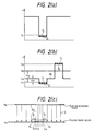
- a first latent image Z1 which is the object of, for example, reverse development and which corresponds to a first image is formed on the latent image carrier 1 which has, for example, a positive charge characteristic. Then, the first latent image Z1 is reversely developed by a first toner which is charged to a positive polarity so as to form a first toner image T1 having a surface potential of VT1, as shown in Fig. 2(a).
- a second latent image Z2 which is the object of normal development and which corresponds to a second image is formed on the latent image carrier 1, and the second latent image Z2 is then normally developed by a second toner which is charged to a negative polarity so as to form a second toner image T2, as shown in Fig. 2(b).
- the background potential VH2 of the second latent image Z2 is set at an intermediate potential of the surface potential VT1 of the first toner image T1 and the image area potential of the second latent image Z2. Since the surface potential VT1 of the first toner image T1 is lower than the background potential VH2, the portion of the first toner image T1 constitutes a kind of potential well with respect to the ambience.
- a magnetic brush holding the second toner brushes against the latent image carrier 1 while a developing bias VB2 is applied. Since the developing bias VB2 is set at a larger value than the background potential VH2 of the second latent image Z2. The second toner is attracted to the second latent image Z2 without adhering to the first toner image portion T1 and the background portion H2 for the second latent image Z2.
- both toner images T1 and T2 on the latent image holder 1 are simultaneously transferred to the transfer medium 7.
- each of the potentials of the first toner image T1 (negative polarity, in this case), the second latent image Z2 and the background portion H2 thereof and the developing bias VB2 are set in the relationship as shown in Fig. 3(a).
- the portion of the first toner image T1 constitutes a kind of potential hill with respect to the ambience.
- an electrostatic field Sn is formed in the direction indicated by the arrow on the basis of the potential difference ⁇ Vn between the peripheral portion of the first toner image T1 and the background portion H2, and an electrostatic force Fn which holds and constrains the first toner image T1 having the negative polarity in the horizontal direction is generated.
- the first toner image T1 is firmly retained on the latent image carrier 1 by the electrostatic forces Fm and Fn, and even if the magnetic brush holding the second toner brushes against the first toner image T1, the disturbance of the first toner image T1 is effectively prevented.
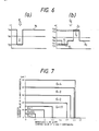
- Fig. 4 shows a first embodiment of a two-color printer to which an image forming method of the present invention is adapted.
- the reference numeral 10 represents a positive charge type photosensitive drum, 11 a charging corotron for charging the photosensitive drum 11 in advance, 12 a first LED array for forming a first latent image 11, 13 a first magnetic brush type developing unit using black toner which is positively charged, 14 a second LED array for forming a second latent image, 15 a second magnetic brush type developing unit using red toner which is negatively charged, 16 a pre-transfer corotron for arranging the charged toners on the photosensitive drum 10 in the same polarity before a transfer step, 17 a transfer corotron for charging a recording sheet 18 to the opposite polarity to that of the toners adjusted by the pre-transfer corotron 16 and for electro-statically transferring the toner image of each color to the recording sheet 18, 19 a static elimination corotron for separating the recording sheet 18 from the photosensitive drum 10 after the transfer step, 20 a static elimination corotron for eliminating the residual charges on the photosensitive drum 10 and residual toner charges before a cleaning step
- a recording image an image consisting of a black image area (GB) and a red image area (GR) on a white ground (W) will be cited, as shown in the above of Fig. 5.
- the photosensitive drum 10 is first uniformly charged positively by the charging corotron 11 (Fig. 5(a)).
- the portion of the photosensitive drum 10 which corresponds to the black image area GB is exposed by the first LED array 12 to obtain a negative image.
- the first latent image Z1 of the photosensitive drum 10 which corresponds to the black image area GB is statically eliminated to a potential of VZ1, while the potentials of the portions of the photosensitive drum 10 which correspond to the white ground W and the red image area GR are maintained at the initial charged potential VH1 (Fig. 5(b)).
- the developing bias VB1 of the first developing unit 13 is set between the potential VP1 of the first latent image Z1 and the initial charged potential VH1, and the first latent image Z1 is reversely developed by black toner positively charged by the first developing unit 13 to form a first toner image T1 (Fig. 5(c)).
- the portion of the photosensitive drum 10 which corresponds to the red image area GR is exposed by the second LED array 14 to obtain a positive image.
- the potential of the second latent image Z2 of the photosensitive drum 10 which corresponds to the red image area GR is maintained at a potential VZ2 which is substantially equal to the initial charged potential VH1, while the background portion H2 except for the second image Z2 is statically eliminated so as to have a potential of VH2 higher than the surface potential VT1 of the first toner image T1 (Fig. 5(d)).
- the developing bias VB2 of the second developing unit 15 is set between the potential VZ2 of the second latent image Z2 and the background potential VH2, and the second latent image Z2 is normally developed by red toner negatively charged by the second developing unit 15 to form a second toner image T2 (Fig. 5(e)).
- the toner images T1 and T2 of the two colors have been formed on the photosensitive drum 10.
- these toner images T1 and T2 are arranged in the same polarity, e.g., a negative polarity, by the pre-transfer corotron 16 (Fig. 5(f)), they are simultaneously transferred to the recording sheet 18 by the transfer corotron 17.
- the recording sheet 18 is passed through the stabilizer 24 to stabilize the toner image of each color on the recording sheet 18.
- Toner images were formed by equalizing the conditions for the first toner image formation process and varying the parameters in the second toner image formation process, and the disturbances of the first toner images T1 and the image densities based on the first and second toner images T1 and T2 were measured.
- the toner image to be measured was a line image of 300 ⁇ m extending in the axial direction (X) and the circumferential direction (Y) of the photosensitive drum 10.
- the disturbance was represented by the line width reproducibility which indicates the ratio of the line width of the reproduced toner image T1 on the assumption that the line width of the line image of a monochrome mode is 1 and the coarseness which indicates the degree of disturbance in the dimension at the edge portion of the reproduced toner image T1.
- Se (selenium) type photosensitive material positive charge type
- Black toner positively charged Carrier . Ferrite carrier having an average particle diameter of 100 ⁇ m .
- Black toner A mixture of 92 parts of a styrene-n-butyl methacrylate copolymer, 8 parts of Carbon Black #4000 (Trade Name, produced by Mitsubishi Chemical Industries, Co., Ltd.) and 2 parts of charging controlling agent (Bontron P-51, Trade Name, produced by Orient Chemical Industries, Co. Ltd.) was melted, kneaded and pulverized to particles having an average particle diameter of 12 ⁇ m. Positively charged with respect to the carrier.
- Red toner negatively charged
- Carrier A magnetic particle dispersion type carrier obtained by melting, kneading and pulverizing a mixture of 35 parts of a styrene-n-butyl methacrylate copolymer and 65 parts of magnetite. Average particle diameter: 30 ⁇ m, and density: 2.2 g/cm3.
- Red toner A mixture of 92 parts of a styrene-n-butyl methacrylate copolymer, 8 parts of a red pigment Lithor Scarlet (Trade Name, produced by BASF) and 2 parts of charging controlling agent (E-84, Trade Name, produced by Orient Chemical Industries, Co. Ltd.) was melted, kneaded and pulverized to particles having an average particle diameter of 12 ⁇ m. Negatively charged with respect to the carrier.
- Trimming gas 0.6 mm .
- Drum Roll Space [Space between the photosensitive drum and the developing roll] 0.8 mm .
- Magnet set angle MMA [Deviation angle of the set position of the main magnetic pole from the developing nip range] +5° .
- the potential VZ1 of the first latent image Z1 was fixed at 200 (V), the background potential VH1 of the first latent image Z1 at 800 (V) and the first developing bias VB1 at 650 (V), as shown in Fig. 6(a).
- the surface potential VT2 of the second toner image, the second developing bias VB2, the background potential VH2 of the second latent image Z2, and the exposure E2 at the time of forming the second latent image on the assumption that the exposure E1 at the time of forming the first latent image was 1 were varied to select the six Examples 1 to 6 shown in Table 1.
- the potentials VZ1 and VZ2 of the first and second latent images Z1 and Z2, respectively, and the surface potential VT1 of the first toner image T1 were fixed at 160 (V), 700 (V) and 190 (V), respectively, with consideration for the darkdecay.
- the suitability means whether the conditions (1) and (2) are satisfied or not. If they are satisfied, the mark O is given, while if they are not, the mark x is given.
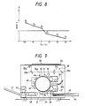
- Table 2 Ex. 1 Ex. 2 Ex. 3 Ex. 4 Ex. 5 Ex. 6 Reproduced line width (X) 1.07 1.14 1.20 1.30 1.40 1.50 Reproduced line width (Y) 1.10 1.17 1.20 1.30 1.35 1.40 Coarseness (X) 6 7 8 10 15 20 Coarseness (Y) 5 6 8 11 14 20 Density of first image 1.60 1.60 1.60 1.50 1.45 Density of second image 0.90 1.05 1.20 1.20 1.20 1.20 1.20
- the images of the Examples 1 to 3 are in the good range, namely, have the grade of 1 or less and the images of the Examples 4 to 6 (represented by P4 to P6 in Fig. 8) are in the bad range, namely, have the grades exceeding 1.
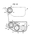
- Fig. 9 shows a second embodiment of a two-color copying machine to which the image forming method of the present invention is adapted.
- the reference numeral 30 represents a negative charge type photosensitive drum serving as a latent image carrier having a photoconductive layer 30a on the periphery therof, 31 a charging corotron for charging the photosensitive drum 30 in advance, 32 an LED array for forming a first latent image, 33 an optical image formation system for forming a second latent image which consists of an exposure lamp 33a for irradiating an original 35 on a platen 34, a group of a plurality of mirrors 33b for introducing the light reflected from the original 35 to a predetermined position of the photosensitive drum 30 and an image formation lens for forming an optical image on the predetermined position of the photosensitive drum, 36 a first magnetic brush type developing unit using black toner which is negatively charged, 37 a second magnetic brush type developing unit using red toner which is positively charged, 38 a pre-transfer corotron for arranging the charged toners on the photosensitive drum 30 in the same polarity before a transfer step, 39 a transfer corotron for
- the second developing unit 37 is composed of a housing 51 which accommodates a developing roll 52, an agitator 53 for agitating a developer, a conveying paddle 54 for supplying the agitated developer g to the developing roll 52, a trimming bar 55 for controlling the trimming gap of the developer g supplied to the periphery of the developing roll 52 and a mixing plate 56 for returning the developer g scraped off by the trimming bar 55 to the side of the agitator 53, as shown in Fig. 10.
- the developing roll 52 is composed of a fixed sleeve 57 of a nonmagnetic material, and a magnet roll 58 which has a multiplicity of propulsion magnetic poles 58a and 58b mounted therearound and which is disposed in the fixed sleeve 57 so as to be rotatable at a predetermined speed.
- the rotational speed of the photosensitive drum 30 is V P
- the moving speed of the developer g of the developing roll 52 is V DEVE
- the condition 0.5 ⁇ V DEVE /V p ⁇ 2.0 is satisfied on the basis of the results of the later-described experiments.
- the fundamental structure of the first developing unit 36 is substantially the same as the second developing unit 37.
- the developing roll 52 of the first developing unit 36 is composed of a rotary sleeve 59 and a magnet roll 60 which has a multiplicity of propulsion magnetic poles 58a and 58b mounted therearound and which is fixed inside the rotary sleeve 59.
- the negative charge type photosensitive drum 30 is first uniformly charged by the charging corotron 31 (Fig. 11(a)), and light is then projected by the LED array 32 in accordance with the image information to form the first negative latent image Z1 on the photosensitive drum 30 (Fig. 11(b)). While an appropriate developing bias VB1 is applied to the developing roll 52 of the first developing unit 36, the first negative latent image Z1 is developed by negatively charged black toner to form the first toner image T1 (Fig. 11(c)).
- the second positive latent image Z2 (the absolute value of the potential VH2 of the background H2 is larger than the absolute value of the surface potential VT1 of the first toner image T1) corresponding to the image of the original 35 is formed on the photosensitive drum 30 by the optical image forming system 33 (Fig. 11(d))
- the second positive latent image Z2 is developed by positively charged red toner to form the second toner image T2 while an appropriate developing bias VB2 is applied to the developing roll 52 of the second developing unit 37 (Fig. 11(e)).
- the toners T1 and T2 on the photosensitive drum 30 are arranged in the same polarity by the pre-transfer corotron 38 and the toner images T1 and T2 are transferred to the copying sheet 40 by the transfer corotron 39.
- the toner images T1 and T2 are stabilized through a predetermined stabilization step.
- the frictional force between the developers g and the photosensitive drum 30 therefore becomes comparatively large.
- magnet roll 58 moves in the direction indicated by the arrow U1, as shown in Fig. 12(a), so that the group of the developers g (carrier g c and toner g t ) in the state of erecting on the fixed sleeve 57 revolves in the direction indicated by the arrow U2 at a predetermined speed V DEVE while each developer rotates on its axis.
- the frictional force between the group of the developers g and the photosensitive drum 30 is restricted to a small force, thereby effectively preventing the disturbance of the first toner image T1.
- Two component type (black toner negatively charged) A mixture of 95 parts by weight of a carrier obtained by coating iron powder with a polymethyl methacrylate copolymer and having an average particle diameter of 100 ⁇ m and 5 parts by weight of a toner obtained by dispersing 7 parts by weight of carbon black in 93 parts by weight of a styrene-n-butyl methacrylate copolymer (copolymerization ratio 80 : 20) and having an average particle diameter of 11 ⁇ m.
- Two component type (red toner positively charged) A mixture of 90 parts by weight of a carrier obtained by mixing, melting, kneading and pulverizing a styrene-n-butyl methacrylate copolymer (density: 1.1 g/cm3) and cubic type magnetite (density: 4.8 g/cm3) in the ratio of 35/65 and having a density of 2.2 g/cm3 and an average particle diameter of 30 ⁇ m, and 10 parts by weight of a toner obtained by melting, kneading and pulverizing 92 parts by weight of a resin obtained by graft polymerization of a styrene butyl methacrylate copolymer with a low-molecular polyolefin and 8 parts by weight of a red pigment "Lithor Scarlet" (Trade Name: produced by BASF) and having an average particle diameter of 9.8 ⁇ m.
- a carrier obtained by mixing, melting,
- the first negative latent image Z1 -60 V
- the background portion of the first negative latent image Z1 -600 V
- the first developing bias VB1 -400 V
- the second positive latent image Z2 -580 V
- the background portion of the second positive latent image Z2 -200 V
- the second developing bias VB2 -300 V
- the number of poles of the second developing unit 37 was charged to 8, 10 and 12 and the revolution number of the magnet roll 58 was varied to 5, 10 15, 25 and 30 (rps).
- the first toner image was a horizontal line image 250 ⁇ m in line width.
- the mark o was given, when it was within 1.2, the mark ⁇ was given, and in the other cases, the mark x was given.
- Table 3 The results are shown in Table 3.
- V DEVE ( ⁇ D x NlRM)/( ⁇ D-Nl)[mm/sec].
- V DEVE NRm.
- the speed ratio of the moving speed V DEVE of the developer with respect to the rotational speed Vp of the photosensitive drum is m.
- the m satisfy the equation 0.5 ⁇ m ⁇ 2.0.
- the m satisfy the equation 0.8 ⁇ m ⁇ 1.5.
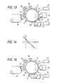
- Fig. 13 shows a third embodiment of a two-color printer to which the image forming method of the present invention is adapted.
- the reference numeral 70 represents a positive charge type photosensitive drum (Se type in this embodiment) serving as a latent image holder having a photoconductive layer 70a on the periphery thereof, 71 a charging corotron, 72 a first LED array for forming a first latent image, 73 a first magnetic brush type developing unit using black toner which is negatively charged, 74 a recharging scorotron serving as a recharger for recharging the photosensitive drum 70, 75 a second LED array for forming a second latent image, 76 a second magnetic brush type developing unit using red toner which is positively charged, 77 a corotron for exposing and charging the photosensitive drum 70 simultaneously, 78 a transfer corotron, 79 a roll type recording sheet roll, 80 a guide roll for the recording sheet 79, 81 a static elimination corotron, 82 a cleaner and 83 a static eliminating lamp.
- a positive charge type photosensitive drum Se type in this embodiment
- 72 a first LED array for forming
- the exposing and charging corotron 77 discharges the photoconductive layer 70a of the photosensitive drum 70 by applying to the corotron 77 AC voltage on which a DC voltage having the same polarity as the photosensitive layer 70a is superposed while uniformly exposing the photoconductive layer 70a.
- Example of the discharging characteristic is shown in Fig. 14.
- the ordinate represents the current I flowing to the surface of the photoconductive layer by the discharging treatment
- the abscissa represents the surface potential VPR of the photoconductive layer 70a
- the potential V0 is set at a higher value in absolute value than the background potential.
- the photoconductive layer 70a of the photosensitive drum 70 which was rotating in the direction indicated by the arrow was first uniformly charged to +1300 (V) by the charging corotron 71 (Fig. 15(a)).
- the portion of the photosensitive drum 70 which corresponded to the first image is exposed by the first LED array 72 to obtain a positive latent image Z1 on the photoconductive layer 70a (Fig. 15(b)).
- the potential VZ1 of the first latent image Z1 after the exposure was +1200 (V) and the potential VH1 of the background portion H1 is +650 (V).
- the first latent image Z1 is normally developed by black toner negatively charged by the first developing unit 73 to form a first toner image T1 (Fig. 15(b)).
- the symbol T1′ represents a first fog toner which adheres to the background portion.
- the photoconductive layer 70a is charged again by the recharging scorotron 74 so that the potential VT1 of the first toner image T1 was +600 (V) and the background potential VH2 is +500 (V) (Fig. 15(c)).
- the portion of the photosensitive drum 70 which corresponds to the second image was exposed by the second LED array 75 to form a negative latent image Z2 (Fig. 15(d)).
- the potential VZ2 of the second latent image Z2 after exposure is +100 (V).
- the second latent image Z2 is reversely developed by the positively charged red toner by the second developing unit 76 to form a second toner image T2 (Fig. 15(d)).
- the symbol T2′ represents a second fog toner which adheres to the background portion.
- the photoconductive layer 70a is next subjected to discharging treatment under uniform exposure by the exposing and charging corotron 77.
- the background portion of the photoconductive layer 70a having no toner images T1 and T2 thereon is made photoconductive by the uniform exposure.
- the photo-conductive layer 70a at those portions does not become photoconductive, so that the surface potential at the positions of the toner images T1 and T2 is kept higher than the background poten-tial (Fig. 15(e)).
- the discharging treatment was carried out by applying to the corotron 77 an AC voltage on wihch superposed is a DC voltage having the positive polarity which is the same as that of the photoconductive layer 70a.
- V0 is set at a slightly higher value (about 50 (V)) in the absolute value than the background potential
- the first and second toner images T1 and T2 at the image area are negatively charged, while the fog toners T1′ and T2′ at the background portion were positively charged (Fig. 15(f)).
- the toner images T1 and T2 are then transferred by the transfer corotron 78 to which a DC voltage having the opposite polarity to that of the toner at the image area is applied.
- the toner images T1 and T2 alone which have been arranged in the negative polarity are transferred to the recording sheet 79, thereby obtaining a good red and black image without fog.
- Fig. 16 shows a fourth embodiment of a two-color printer to which the present invention is adapted.
- the fundamental structure thereof is substantially the same as that of the above-described Embodiment 3.
- the recharging corotron 74 is not used, and in place of the exposing and discharging corotron 77, a pre-transfer exposure lamp 91 and a pre-transfer charging corotron 92 which are functionally separated from each other are used.
- the same numerals are provided for the elements which are the same as those in the Embodiment 3, and explanation thereof will be omitted.
- the first LED array 72 exposes to obtain a negative image corresponding to the first image
- the second LED array 75 exposes to obtain a positive image corresponding to the second image.
- the first developing unit 73 carries positively charged black toner
- the second developing unit 76 carries negatively charged red toner.
- the photoconductive layer 70a of the photosensitive drum 70 is first uniformly charged to +1000 (V) by the charging corotron 71 (Fig. 17(a)).
- the portion of the photosensitive drum 70 which corresponds to the first image is exposed by the first LED array 72 to obtain a negative latent image Z1 on the photoconductive layer 70a (Fig. 17(b)).
- the potential VZ1 of the first latent image Z1 after the exposure is +250 (V) and the potential VH1 of the background portion H1 is +900 (V).
- the first latent image Z1 is reversely developed by positively charged black toner by the first developing unit 73 to form a first toner image T1 (Fig. 17(b)).
- the symbol T1′ represents a first fog toner which adheres to the background portion.
- the portion of the photosensitive drum 70 which corresponded to the second image is exposed by the second LED array 75 to form a positive latent image Z2 (Fig. 17(c)).
- the potential VZ2 of the second latent image Z2 after the exposure is +800 (V)
- the background potential VH2 is 300 (V)
- the surface potential VT1 of the first toner image T1 is 200 (V).
- the second latent image Z2 is normally developed by negatively charged red toner by the second developing unit 76 to form a second toner image T2 (Fig. 17(c)).
- the symbol T2′ represents a second fog toner which adheres to the background portion.
- the photoconductive layer 70a was next subjected to discharging treatment by the uniform exposure by the pre-transfer exposure lamp 91 (Fig. 17(e)).
- the photoconductive layer 70a was next subjected to discharging treatment by the pre-transfer charging corotron 92.
- the first and second toner images T1 and T2 at the image area are negatively charged, while the fog toners T1′ and T2′ at the background portion are positively charged (Fig. 17(e)).
- the toner images T1 and T2 are then transferred by the transfer corotron 78 to which a DC voltage having the opposite polarity to that of the toner at the image area is applied is applied.
- a DC voltage having the opposite polarity to that of the toner at the image area is applied is applied.
- the toner images T1 and T2 alone which have been arranged in the negative polarity are transferred to the recording sheet 79, thereby obtaining a good red and black image without fog.
- toners having the opposite polarities are used to form toner images of two types and a force for preventing the disturbance of the first toner image is provided in the second toner image formation process, it is possible to form a good image based on the toner images of two types while effectively preventing the toners of two types from mixing and the first toner image from being disturbed.
- a method of forming an image in the present invention it is possible to realize the formation of two types with good efficiency in the case of using a photosensitive material as a latent image holder or carrier.
- a photosensitive material as a latent image holder or carrier.
- the photosensitive material is initially charged, it is possible to secure a sufficiently large contrast between the first and second latent images without the need for recharging in the middle course of processing, thereby facilitating the formation of an image having a sufficient density.
- the constraining force of the magnetic brush with respect to the developer holder in the second developing means is weakened in the developing nip range on the basis of the field of a repulsion magnetic pole, the frictional force between the magnetic brush and the latent image holder in the developing nip range is suppressed, and the disturbance of the first toner image is safely prevented to that degree.
- the second developing means is devised so as to suppress the frictional force between the magnetic brush and the latent image holder in the range which keeps the developing capacity, it is possible to safely prevent the disturbance of the first toner image without impairing the state of the formation of the second toner image.
- an image forming apparatus of the present invention it is possible to transfer toner images having different polarities to a transfer medium with good efficiency by utilizing an electrostatic trans-fer system.
- an AC voltage to which is superposed DC component having the same polarity as the charged polarity of the latent image carrier is applied to the charging means, it is possible to effectively make the polarities of the toner at the image area and the toner at the background portion different from each other.
Landscapes
- Physics & Mathematics (AREA)
- General Physics & Mathematics (AREA)
- Color Electrophotography (AREA)
Applications Claiming Priority (8)
| Application Number | Priority Date | Filing Date | Title |
|---|---|---|---|
| JP14330187 | 1987-06-10 | ||
| JP143301/87 | 1987-06-10 | ||
| JP198300/87 | 1987-08-10 | ||
| JP19830087 | 1987-08-10 | ||
| JP3081688 | 1988-02-15 | ||
| JP30816/88 | 1988-02-15 | ||
| JP138399/88 | 1988-06-07 | ||
| JP63138399A JPH087478B2 (ja) | 1987-06-10 | 1988-06-07 | 画像形成方法及びその装置 |
Publications (3)
| Publication Number | Publication Date |
|---|---|
| EP0294824A2 true EP0294824A2 (fr) | 1988-12-14 |
| EP0294824A3 EP0294824A3 (en) | 1990-09-12 |
| EP0294824B1 EP0294824B1 (fr) | 1994-04-06 |
Family
ID=27459320
Family Applications (1)
| Application Number | Title | Priority Date | Filing Date |
|---|---|---|---|
| EP88109255A Expired - Lifetime EP0294824B1 (fr) | 1987-06-10 | 1988-06-10 | Procédé de formation d'images et appareil utilisant un tel procédé |
Country Status (3)
| Country | Link |
|---|---|
| EP (1) | EP0294824B1 (fr) |
| JP (1) | JPH087478B2 (fr) |
| DE (1) | DE3888873T2 (fr) |
Cited By (2)
| Publication number | Priority date | Publication date | Assignee | Title |
|---|---|---|---|---|
| EP0465211A3 (en) * | 1990-07-02 | 1992-09-16 | Xerox Corporation | Highlight printing apparatus |
| EP0503878A3 (en) * | 1991-03-11 | 1993-07-28 | Xerox Corporation | Development apparatus |
Families Citing this family (2)
| Publication number | Priority date | Publication date | Assignee | Title |
|---|---|---|---|---|
| JPH087475B2 (ja) * | 1990-01-29 | 1996-01-29 | 富士ゼロックス株式会社 | カラー画像形成装置及びその使用方法 |
| JP3234855B2 (ja) * | 1995-08-29 | 2001-12-04 | 株式会社日立製作所 | 電子写真記録装置 |
Family Cites Families (6)
| Publication number | Priority date | Publication date | Assignee | Title |
|---|---|---|---|---|
| JPS572047A (en) * | 1980-06-06 | 1982-01-07 | Hitachi Ltd | Two color electrostatic recording method |
| JPS57188061A (en) * | 1981-05-15 | 1982-11-18 | Hitachi Ltd | Electrophotographing device |
| US4660961A (en) * | 1984-06-07 | 1987-04-28 | Matsushita Electric Industrial Co., Ltd. | Copying apparatus for synthesizing images |
| JPS61219964A (ja) * | 1985-03-26 | 1986-09-30 | Casio Comput Co Ltd | 2色画像形成方法 |
| US4831408A (en) * | 1986-08-08 | 1989-05-16 | Canon Kabushiki Kaisha | Electrophotographic apparatus capable of forming images in different colors |
| JPS6341874A (ja) * | 1986-08-08 | 1988-02-23 | Canon Inc | 2色電子写真方法 |
-
1988
- 1988-06-07 JP JP63138399A patent/JPH087478B2/ja not_active Expired - Fee Related
- 1988-06-10 DE DE3888873T patent/DE3888873T2/de not_active Expired - Lifetime
- 1988-06-10 EP EP88109255A patent/EP0294824B1/fr not_active Expired - Lifetime
Cited By (2)
| Publication number | Priority date | Publication date | Assignee | Title |
|---|---|---|---|---|
| EP0465211A3 (en) * | 1990-07-02 | 1992-09-16 | Xerox Corporation | Highlight printing apparatus |
| EP0503878A3 (en) * | 1991-03-11 | 1993-07-28 | Xerox Corporation | Development apparatus |
Also Published As
| Publication number | Publication date |
|---|---|
| EP0294824B1 (fr) | 1994-04-06 |
| JPH087478B2 (ja) | 1996-01-29 |
| DE3888873D1 (de) | 1994-05-11 |
| EP0294824A3 (en) | 1990-09-12 |
| JPH01287581A (ja) | 1989-11-20 |
| DE3888873T2 (de) | 1994-11-10 |
Similar Documents
| Publication | Publication Date | Title |
|---|---|---|
| US5489975A (en) | Image forming method and apparatus | |
| US4937629A (en) | Composite image recording apparatus | |
| US3649262A (en) | Simultaneous development-cleaning of the same area of an electrostatographic image support surface | |
| EP0401437B1 (fr) | Appareil de formation d'images avec accentuation des couleurs | |
| US4349270A (en) | Developer removing device for copying apparatus | |
| EP0354310A1 (fr) | Procédé et dispositif pour le tirage électrophotographique | |
| JP3248047B2 (ja) | 画像形成装置 | |
| US5024181A (en) | Method for the development of an electrostatic latent image | |
| EP0294824B1 (fr) | Procédé de formation d'images et appareil utilisant un tel procédé | |
| US4640883A (en) | Method of forming composite or dichromatic images | |
| CA1112500A (fr) | Materiaux porteurs de particules isolantes et conductrices | |
| JPS61226773A (ja) | 像形成方法及びその装置 | |
| JP2606476B2 (ja) | 多色記録方法 | |
| JPH05323681A (ja) | 現像方法 | |
| JPH11231641A (ja) | 多色画像形成装置 | |
| JPH0248683A (ja) | 画像形成装置 | |
| JPS613153A (ja) | 現像方法 | |
| JPS63254472A (ja) | カラ−画像記録方法 | |
| JPS6243678A (ja) | 多色像形成装置 | |
| JPS6243661A (ja) | 多色像形成装置 | |
| JP2001125369A (ja) | 現像装置 | |
| JPH0695510A (ja) | 現像方法 | |
| JP2004021095A (ja) | 現像方法及び現像装置及び画像形成方法及び画像形成装置 | |
| JPH04329563A (ja) | カラー画像記録方法 | |
| JPS6073546A (ja) | 乾式現像剤 |
Legal Events
| Date | Code | Title | Description |
|---|---|---|---|
| PUAI | Public reference made under article 153(3) epc to a published international application that has entered the european phase |
Free format text: ORIGINAL CODE: 0009012 |
|
| AK | Designated contracting states |
Kind code of ref document: A2 Designated state(s): DE GB |
|
| PUAL | Search report despatched |
Free format text: ORIGINAL CODE: 0009013 |
|
| AK | Designated contracting states |
Kind code of ref document: A3 Designated state(s): DE GB |
|
| 17P | Request for examination filed |
Effective date: 19900928 |
|
| 17Q | First examination report despatched |
Effective date: 19920220 |
|
| GRAA | (expected) grant |
Free format text: ORIGINAL CODE: 0009210 |
|
| AK | Designated contracting states |
Kind code of ref document: B1 Designated state(s): DE GB |
|
| REF | Corresponds to: |
Ref document number: 3888873 Country of ref document: DE Date of ref document: 19940511 |
|
| PLBE | No opposition filed within time limit |
Free format text: ORIGINAL CODE: 0009261 |
|
| STAA | Information on the status of an ep patent application or granted ep patent |
Free format text: STATUS: NO OPPOSITION FILED WITHIN TIME LIMIT |
|
| 26N | No opposition filed | ||
| REG | Reference to a national code |
Ref country code: GB Ref legal event code: IF02 |
|
| PGFP | Annual fee paid to national office [announced via postgrant information from national office to epo] |
Ref country code: DE Payment date: 20070607 Year of fee payment: 20 |
|
| PGFP | Annual fee paid to national office [announced via postgrant information from national office to epo] |
Ref country code: GB Payment date: 20070606 Year of fee payment: 20 |
|
| REG | Reference to a national code |
Ref country code: GB Ref legal event code: PE20 Expiry date: 20080609 |
|
| PG25 | Lapsed in a contracting state [announced via postgrant information from national office to epo] |
Ref country code: GB Free format text: LAPSE BECAUSE OF EXPIRATION OF PROTECTION Effective date: 20080609 |