EP0295102A2 - Dispositif pour renforcer le déplacement d'un élément piézoélectrique ou d'un élément semblable - Google Patents
Dispositif pour renforcer le déplacement d'un élément piézoélectrique ou d'un élément semblable Download PDFInfo
- Publication number
- EP0295102A2 EP0295102A2 EP88305280A EP88305280A EP0295102A2 EP 0295102 A2 EP0295102 A2 EP 0295102A2 EP 88305280 A EP88305280 A EP 88305280A EP 88305280 A EP88305280 A EP 88305280A EP 0295102 A2 EP0295102 A2 EP 0295102A2
- Authority
- EP
- European Patent Office
- Prior art keywords
- piezoelectric element
- displacement
- frame
- movable member
- leaf springs
- Prior art date
- Legal status (The legal status is an assumption and is not a legal conclusion. Google has not performed a legal analysis and makes no representation as to the accuracy of the status listed.)
- Granted
Links
Images













Classifications
-
- H—ELECTRICITY
- H02—GENERATION; CONVERSION OR DISTRIBUTION OF ELECTRIC POWER
- H02N—ELECTRIC MACHINES NOT OTHERWISE PROVIDED FOR
- H02N2/00—Electric machines in general using piezoelectric effect, electrostriction or magnetostriction
- H02N2/02—Electric machines in general using piezoelectric effect, electrostriction or magnetostriction producing linear motion, e.g. actuators; Linear positioners ; Linear motors
- H02N2/04—Constructional details
- H02N2/043—Mechanical transmission means, e.g. for stroke amplification
-
- B—PERFORMING OPERATIONS; TRANSPORTING
- B41—PRINTING; LINING MACHINES; TYPEWRITERS; STAMPS
- B41J—TYPEWRITERS; SELECTIVE PRINTING MECHANISMS, i.e. MECHANISMS PRINTING OTHERWISE THAN FROM A FORME; CORRECTION OF TYPOGRAPHICAL ERRORS
- B41J2/00—Typewriters or selective printing mechanisms characterised by the printing or marking process for which they are designed
- B41J2/22—Typewriters or selective printing mechanisms characterised by the printing or marking process for which they are designed characterised by selective application of impact or pressure on a printing material or impression-transfer material
- B41J2/23—Typewriters or selective printing mechanisms characterised by the printing or marking process for which they are designed characterised by selective application of impact or pressure on a printing material or impression-transfer material using print wires
- B41J2/27—Actuators for print wires
- B41J2/295—Actuators for print wires using piezoelectric elements
-
- H—ELECTRICITY
- H02—GENERATION; CONVERSION OR DISTRIBUTION OF ELECTRIC POWER
- H02N—ELECTRIC MACHINES NOT OTHERWISE PROVIDED FOR
- H02N2/00—Electric machines in general using piezoelectric effect, electrostriction or magnetostriction
- H02N2/22—Methods relating to manufacturing, e.g. assembling, calibration
Definitions
- the present invention relates to an actuator for driving a printing wire or the like in a printing head, for example, and more particularly to a device for magnifying displacement of a piezoelectric element or the like as a driving source wherein expansion and contraction of the piezoelectric element is magnified through a rolling motion of a rolling member into a relatively large movement of the printing wire to carry out a printing operation of the printing wire.
- the present invention also relates to a method of producing such a device as mentioned above.
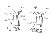
- a device for magnifying displacement of a piezoelectric element as shown in Figs. 39(A) and 39(B).
- Figs. 39(A) and 39(B) which show a rest condition and an operative condition of the device, respectively, a piezoelectric element 302 is fixed to a frame 300, and a rolling member 308 is connected through a pair of leaf springs 304 and 306 spaced a given distance from each other to the piezoelectric element 302 and the frame 300.
- Fig. 39(A) and 39(B) which show a rest condition and an operative condition of the device, respectively.
- a printing wire is connected directly to one end of the rolling member 308 or indirectly such as through another member to the one end of the rolling member 308, thus constructing a printing unit.
- a plurality of the printing units of the number equal to that of the printing wires are installed in the printing head.
- Each printing unit includes the piezoelectric element 302, and lead wires extending from both electrodes of the piezoelectric element 302 are guided to a certain wiring board, and are connected to feeder lines formed on the wiring board by soldering or the like.
- lead wires they tend to be tangled with each other, making the connecting operation difficult. Further, it is also difficult to recognize the polarity of the lead wires.
- the plurality of printing units are usually located between two parallel base plates, and the frame 300 of each printing unit is fixed to the base plates by a suitable fixing means such as bolts directed parallel to a direction of displacement of the piezoelectric element 302.
- a suitable fixing means such as bolts directed parallel to a direction of displacement of the piezoelectric element 302.
- the frame 300 is expanded parallel to the direction of displacement of the piezoelectric element 302. Further, a fixed position of the frame 300 with respect to the direction parallel to the direction of displacement is slipped.
- a device for magnifying displacement of a piezoelectric element adapted to be displaced by application of voltage thereto, comprising a frame extending substantially parallel to a direction of displacement of the piezoelectric element and mounting the piezoelectric element thereon, a movable member fixed to one end of the piezoelectric element with respect to the direction of displacement, a first mount surface formed on the frame and extending substantially parallel to the direction of displacement, a second mount surface formed on the movable member and extending substantially parallel to the direction of displacement, said second mount surface being opposed to the first mount surface, a first leaf spring mounted at its one end portion on the first mount surface and extending substantially parallel to the direction of displacement, a second leaf spring mounted at its one end portion on the second mount surface and extending substantially parallel to the direction of displacement, and a deflecting member fixed to the other end portions of the first and second leaf springs, wherein when the piezoelectric element is displaced, the second leaf spring is displaced along the first leaf
- a device for magnifying displacement of a piezoelectric element adapted to be displaced by application of voltage thereto, comprising a frame extending substantially parallel to a direction of displacement of the piezoelectric element and mounting the piezoelectric element thereon, a movable member fixed to one end of the piezoelectric element with respect to the direction of displacement, a first mount surface formed on the frame and extending substantially parallel to the direction of displacement, a second mount surface formed on the movable member and extending substantially parallel to the direction of displacement, said second mount surface being opposed to the first mount surface, a first leaf spring mounted at its one end portion on the first mount surface and extending substantially parallel to the direction of displacement, a second leaf spring mounted at its one end portion on the second mount surface and extending substantially parallel to the direction of displacement, and a deflecting member fixed to the other end portions of the first and second leaf springs, wherein when the piezoelectric element is displaced, the second leaf spring is displaced along the first leaf
- a device for magnifying displacement of a piezoelectric element adapted to be displaced by application of voltage thereto, comprising a frame extending along the piezoelectric element and having a base portion for supporting one end of the piezoelectric element with respect to a direction of displacement, a movable member fixed to the other end of the piezoelectric element, a pair of first and second leaf springs fixed at their one end portions to the frame and the movable member, and a deflecting member fixed to the other end portions of the leaf springs, wherein when the piezoelectric element is displaced, the leaf springs are deformed to rotate the deflecting member; wherein the leaf springs are formed from a single spring member to define a split groove therein extending from one end of the spring member toward the other end thereof, and the rolling member is integrally connected to the other end of the spring member.
- a device for magnifying displacement of a piezoelectric element adapted to be displaced by application of voltage thereto, comprising a frame extending along the piezoelectric element and having a base portion for supporting one end of the piezoelectric element with respect to a direction of displacement, a movable member fixed to the other end of the piezoelectric element, a pair of first and second leaf springs fixed at their one end portions to the frame and the movable member, and a deflecting member fixed to the other end portions of the leaf springs, wherein when the piezoelectric element is displaced, the leaf springs are deformed to rotate the deflecting member; wherein the first and second leaf springs are formed with a small sectional area portion at a portion except the fixed ends of the leaf springs, said small sectional area portion having a small sectional area in a direction substantially perpendicular to the direction of displacement of the piezoelectric element smaller than a sectional area of the fixed ends.
- a device for magnifying displacement of a piezoelectric element adapted to be displaced by application of voltage thereto, comprising a frame extending substantially parallel to a direction of displacement of the piezoelectric element and mounting the piezoelectric element on a base portion thereof, a movable member fixed to one end of the piezoelectric element with respect to the direction of displacement, a first mount surface formed on the frame and extending substantially parallel to the direction of displacement, a second mount surface formed on the movable member and extending substantially parallel to the direction of displacement, said second mount surface being opposed to the first mount surface, a first leaf spring mounted at its one end portion on the first mount surface and extending substantially parallel to the direction of displacement, a second leaf spring mounted at its one end portion on the second mount surface and extending substantially parallel to the direction of displacement, and a deflecting member fixed to the other end portions of the first and second leaf springs, wherein when the piezoelectric element is displaced, the second leaf spring is displaced
- a device for magnifying displacement of a piezoelectric element adapted to be displaced by application of voltage thereto, comprising a frame extending substantially parallel to a direction of displacement of the piezoelectric element and mounting the piezoelectric element on a base portion thereof, a movable member fixed to one end of the piezoelectric element with respect to the direction of displacement, a first mount surface formed on the frame and extending substantially parallel to the direction of displacement, a second mount surface formed on the movable member and extending substantially parallel to the direction of displacement, said second mount surface being opposed to the first mount surface, a first leaf spring mounted at its one end portion on the first mount surface and extending substantially parallel to the direction of displacement, a second leaf spring mounted at its one end portion on the second mount surface and extending substantially parallel to the direction of displacement, and a deflecting member fixed to the other end portions of the first and second leaf springs, wherein when the piezoelectric element is displaced, the second leaf spring is displaced
- a method of producing a device for magnifying displacement of a piezoelectric element adapted to be displaced by application of voltage thereto comprising a frame extending substantially parallel to a direction of displacement of the piezoelectric element and mounting the piezoelectric element thereon, a movable member fixed to one end of the piezoelectric element with respect to the direction of displacement, a first mount surface formed on the frame and extending substantially parallel to the direction of displacement, a second mount surface formed on the movable member and extending substantially parallel to the direction of displacement, said second mount surface being opposed to the first mount surface, a first leaf spring mounted at its one end portion on the first mount surface and extending substantially parallel to the direction of displacement, a second leaf spring mounted at its one end portion on the second mount surface and extending substantially parallel to the direction of displacement, and a deflecting member fixed to the other end portions of the first and second leaf springs, wherein when the piezoelectric element is displaced, the second leaf spring is displaced, the second leaf spring is displaced, the second leaf spring
- an impact dot printing head of a type to be driven by a piezoelectric element adapted to be displaced by application of voltage thereto comprising a plurality of printing units each having a printing wire for printing dots onto a printing medium, a displacement transmitting mechanism for transmitting displacement of the piezoelectric element to the printing wire, and a frame for supporting the piezoelectric element and the displacement transmitting mechanism, said frame extending in a direction of displacement of the piezoelectric element; a first base plate for fixedly supporting one end of the frame with respect to the direction of displacement of the piezoelectric element; a second base plate for fixedly supporting the other end of the frame with respect to the direction of displacement of the piezoelectric element, said second base plate having a nose portion for supporting the printing wire; a first fixing means for fixing the first base plate to the frame; and a second fixing means for fixing the second base plate to the frame, wherein at least one of the first and second fixing means is so arranged as to intersect the
- an impact dot printing head of a type to be driven by a piezoelectric element adapted to be displaced by application of voltage thereto comprising a displacement transmitting mechanism for transmitting displacement of the piezoelectric element to a printing wire for printing dots onto a printing medium; a base plate for supporting the piezoelectric element; a wiring board fixed to the base plate for supporting a feeder line to be electrically connected to a lead wire connected to the piezoelectric element; and a holder having a cylindrical portion to be engaged with an outer periphery of the piezoelectric element and a leg portion extending from one end of the cylindrical portion toward the wiring board, said leg portion having a through-hole for inserting the lead wire.
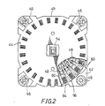
- a head body 40 primarily consists of first and second substantially rectangular base plates 42 and 44 opposed to each other at a predetermined distance, and four posts 46 connecting the base plates 42 and 44 at the four corners thereof.
- a plurality of (twenty four, for example) printing units 48 are provided between the first and second base plates 42 and 44 in such a manner as to be arranged on a circle concentric with a common center line of both the base plates 42 and 44.
- the second base plate 44 is formed with a substantially circular plate portion 49 disposed along the printing units 48, and with a hollow nose portion 54 extending outward from the plate portion 49.
- the nose portion 54 includes a plurality of guide plates 52 for guiding the movement of each printing wire 50 connected to each printing unit 48.
- a support member 56 is provided on the inner surface of the second base plate 44 to position and support each printing unit 48.
- the support member 56 primarily consists of a circular support plate 58 disposed along the inner surface of the second base plate 44 and a plurality of partition walls 60 radially extending inward from the support plate 58 in such a manner that each partition wall 60 is interposed between the adjacent printing units 48.
- the partition walls 60 are integrally formed with a support ring 64 for supporting the outer surface of each frame 62 of the printing units 48.
- the support plate 58 is formed at its central portion with a central hole 66 communicated with the axial hole of the nose portion 54.
- a plurality of guide pins 70 project from the inner surface of the support plate 58 in such a manner as to be arranged around the central hole 66, for guiding each wire driving arm 96 of the printing units 48.
- each printing unit 48 includes a piezoelectric element 72 adapted to be expanded and contracted by the application of voltage thereto and a displacement transmitting mechanism 74 adapted to magnify the expansion and contraction of the piezoelectric element 72 and transmit such a magnified displacement to the printing wire 50.
- the piezoelectric element 72 and the displacement transmitting mechanism 74 are supported to the frame 62.
- the frame 62 is formed of a metal plate having a predetermined thickness and an elongated shape in such a manner as to extend in substantially parallel to the displacement direction of the piezoelectric element 72.
- the frame 62 is formed at its lower end with a laterally extending base portion 78 for supporting one end of the piezoelectric element 72 through a temperature compensation member 76.
- the piezoelectric element 72 is formed by a stack of piezoelectric ceramics adapted to be expanded and contracted in the direction of the stack (in the longitudinal direction of the piezoelectric element 72).
- the temperature compensation member 76 is fixed to one end surface of the piezoelectric element 72 by an adhesive or the like.
- the piezoelectric element 72 is supported through the temperature compensation member 76 onto a support surface 80 of the support portion 78.
- a rectangular movable member 82 is fixed to the other end surface of the piezoelectric element 72 by an adhesive or the like.
- the movable member 82 has a side surface opposed to an upper side surface of the frame 62 with a given spacing defined therebetween.
- the given spacing is filled with a pair of first and second leaf springs 84 and 86 to be fixed to spring mounting surfaces 88 and 90 of the frame 62 and the movable member 82, respectively.
- the spring mounting surfaces 88 and 90 are flat surfaces extending in substantially parallel to the displacement direction of the piezoelectric element 72.
- the spring mount surface 90 of the movable member 82 is located at an end surface of the movable member 82 offset from a center line of the piezoelectric element 72 to the frame 62.
- the first leaf spring 84 has a side surface entirely fixed by brazing or the like to the spring mounting surface 88 of the frame 62, while the second leaf spring 86 has a side surface entirely fixed by brazing or the like to the spring mounting surface 90 of the movable member 82.
- the second leaf spring 86 is movable relative to the first leaf spring 84 under the condition where the opposed surfaces of both the leaf springs 84 and 86 are in contact.
- the first and second leaf springs 84 and 86 extend upward by a given length from the upper ends of the spring mounting surfaces 88 and 90 along the displacement direction of the piezoelectric element 72.
- a deflecting or rolling member 92 is fixed to the upper ends of the first and second leaf springs 84 and 86.
- the rolling member 92 primarily consists of a base member 94 having a high rigidity and a lightweight wire driving arm 96 connected to the base member 94.
- the base member 94 of the rolling member 92 is formed at its lower surface with a horizontal recess 98 for receiving the upper ends of the first and second leaf springs 84 and 86.
- the surfaces (back surfaces) opposite the facing surfaces of the leaf springs 84 and 86 are fixed by brazing to the inner surface of the recess 98.
- the base member 94 is further formed at its front surface with a vertical recess 100 for receiving the base portion of the wire driving arm 96.
- the base portion is fixed in the vertical recess 100 by brazing.
- the printing wire 50 is fixed at its one end to the front end of the wire driving arm 96 by brazing.
- connection member 104 In order to move the movable member 82 in parallel to the displacement direction of the piezoelectric element 72, there is provided an elastically deformable connection member 104 between the frame 62 and the movable member 82.
- the connection member 104 extends vertically along the displacement direction of the piezoelectric element 72 on the opposite side of the frame 62 with respect to the piezoelectric element 72.
- a lower end portion of the connection member 104 is fixed to an end surface of the base portion 78 of the frame 62, while an upper end portion of the connection member 104 is fixed to a front end surface of the movable member 82 on the opposite side of the second leaf spring 86.
- connection member 104 is formed by a thin-walled planar material having a width in a plane parallel to the side surface of the frame 62. Such arrangement of the connection member 104 contributes to ensure a high rigidity of the connection member 104 in a rolling direction of the movable member 82 rolled by a reaction force of the leaf spring 86. Further, an elastic force of the connecting member 104 is set so that the moving force of the movable member 82 due to the expansion of the piezoelectric element 72 may be applied substantially uniformly to the leaf spring 86 and the connection member 104. That is, the elastic force of the connection member 104 is set to be smaller than that of the leaf spring 86.
- the ratio of the elastic forces of the connection member 104 and the leaf spring 86 is set to be about 1:1.5 under the unoperational condition of the piezoelectric element 72. This is due to the fact that when the leaf spring 86 is curved by the upward movement of the movable member 82, a substantially vertical component (a component in the displacement direction of the piezoelectric element 72) of the elastic force of the leaf spring 86 is required to be equal to the elastic force of the connection member 104 under the operational condition. Therefore, the elastic force of the connection member 104 is set to be smaller than that of the leaf spring 86.
- connection member 104 If the elastic force of the connection member 104 is greater than that of the leaf sprng 86 under the operational condition of the piezoelectric element 72, the movable member generates a clockwise moment to hinder smooth vertical motion of the movable member 82 and also badly affect smooth expansion of the piezoelectric element 72. Thus, the provision of the connection member 104 contributes to substantially prevent the inclination of the movable member 82.
- a back stopper 106 formed of low elastic rubber is fixed at an upper end of the connection member 104, so that when the rolling member 92 is rolled and returned, the lower edge of the wire driving arm 96 abuts against the upper surface of the back stopper 106.
- the back stopper 106 is formed with a recess 108 for receiving the upper end portion of the connection member 104, and is further formed with a side hole 110 for filling an adhesive therethrough into the recess 108.
- the back stopper 106 is fixed to the connection member 104 by the adhesive.
- the temperature compensation member 76 bonded to the lower surface of the piezoelectric element 72 functions to compensate the expansion or contraction of the piezoelectric element 72 due to a peripheral temperature change and thereby maintain constant the height from the support surface 80 of the base portion 78 of the frame 62 to the upper end of the piezoelectric element 72.
- a thrust pin 112 is fitted into the base portion 78 for supporting the lower surface of the temperature compensation member 76, and is then fixed integrally with the base portion 78 by means of beam welding.
- the thrust pin 112 operates to slightly upwardly thrust the lower surface of the temperature compensation member 76 on the support surface 80, thereby applying the spring forces of the connection member 104 and the second leaf spring 86 to the piezoelectric element 72 at all times.
- Lead wires 114 and 116 are connected at respective each one end to both electrodes of the piezoelectric element 72 of each printing unit 48, and are connected at respective each other end to given feeder lines 122 by welding.
- the feeder lines 122 are supported on a wiring plate 120 formed of an electrical insulator material.
- the wiring plate 120 is fixed to the outer surface of the first base plate 42.
- the lead wires 114 and 116 are supported on a holder 118 formed of an electrical insulator material.
- Each holder 118 is primarily composed of a rectangular cylindrical portion 124 surroundingly engaged with the outer periphery of the piezoelectric element 72 and a leg portion 128 extending from one side of the cylindrical portion 124 through a hole 126 formed through the first base plate 42 to the inner surface of the wiring plate 120.
- the leg portion 128 of the holder 118 is formed on its one side surface with a pair of guide channels 130 and 132 for guiding and supporting the lead wires 114 and 116 led out from both the electrodes of the piezoelectric element 72 toward the wiring plate 120.
- the leg portion 128 is further formed at its lower end with a projection 134 projecting from the one side surface of the leg portion 128.
- the projection 134 has a pair of guide holes 136 and 138 straight communicated with the guide channels 130 and 132.
- the wiring plate 120 also has a pair of guide holes 140 and 142 straight communicated with the guide holes 136 and 138 of the projection 134.
- the lead wires 114 and 116 guided by the guide channels 130 and 132 pass through the guide holes 136 and 138 of the projection 134 and the guide holes 140 and 142 of the wiring plate 120. Then, the lead wires 114 and 116 from the guide holes 140 and 142 are connected by soldering to the feeder lines 122.
- the rectangular cylindrical portion 124 is formed at its lower end on the opposite side of the leg portion 128 with a downward projection 143 bonded at its lower end to the temperature compensation member 76, so as to support the cylindrical portion 124.
- the cylindrical portion 124 is loosely fitted around the piezoelectric element 72 so as not to hinder the expansion and contraction of the piezoelectric element 72.
- the feeder lines 122 on the wiring plate 120 are supplied with a signal corresponding to print data from a control circuit.
- the inner surface of the first base plate 42 is defined as a reference surface F, and one end surface of the frame 62 of each printing unit 48 is brought into abutment against the reference surface F. Then, a tightening screw 144 is threadly inserted from the outer surface of the first base plate 42 in a direction parallel to the displacement direction of the piezoelectric element 72 into one end portion of the frame 62, thus fixing the one end portion of the frame 62 to the first base plate 42.
- the circular plate portion 49 of the second base plate 44 is formed at its outer periphery on the inner surface thereof with a plurality of mounting projections 148 projecting inwardly perpendicularly therefrom.
- Each projection 148 has a hole 150 elongated in a direction parallel to the displacement direction of the piezoelectric element 72.
- a tightening screw 146 is inserted through each hole 150 of the projection 148 in a direction instersecting the displacement direction, preferably in a direction perpendicular thereto, and is threaded into a mounting projection 152 projecting outwardly from the other end surface of the frame 62, thus fixing the other end portion of the first base plate 44.
- the support posts 46 of the head body 40, the frames 62 and the connection members 104 of the printing units 48 are formed of a material having the same coefficient of linear thermal expansion, so as to cope with a temperature change.
- the piezoelectric element 72 is expanded by a fixed length in the direction of stack of the ceramics, namely, in the direction of arrow X shown in Fig. 4 to thereby lift the movable member 82.
- the second leaf spring 86 receives the moving force of the movable member 82, and is accordingly lifted along the first leaf spring 84.
- the second leaf spring 86 is elastically deformed to be curved between the movable member 82 and the base portion 94 of the rolling member 92.
- Such an elastic deformation of the second leaf spring 86 generates a moment in the direction of arrow P shown in Fig. 4.
- the first leaf spring 84 is slightly elastically deformed, and simultaneously the rolling member 92 is rolled, so that the printing wire 50 connected at the tip of the rolling member 92 is driven to advance as being guided by the guide plates 52. Accordingly, an end of the printing wire 50 is forced against a printing ribbon (not shown), thus carrying out printing.
- the opposed surfaces of the first and second leaf springs 84 and 86 contact with each other.
- the preferred embodiment can provide a greater magnification of expansion of the piezoelectric element 72 owing to the above arrangement of the leaf springs 84 and 86. Accordingly, a requisite stroke of the printing wire 50 can be sufficiently provided.
- the piezoelectric element 72 under the expanded condition is returned to its original condition. Then, the movable member 82, the leaf springs 84 and 86 and the rolling member 92 are all returned to their original condition, thus retracting the printing wire 50 to its original position.
- the flat surfaces of the first and second leaf springs 84 and 86 are fixed by brazing or the like to the flat spring mounting surfaces 88 and 90 of the frame 62 and the movable member 82. Therefore, large fixing areas between the frame 62 and the first leaf spring 84 and between the movable member 82 and the second leaf spring 86 may be provided to thereby ensure strong and stable fixed condition. Furthermore, as the volumes of the frame 62 and the movable member 82 are large, these members may have a large rigidity.
- the base portion 94 of the rolling member 92 as fixed to the respective end portions of the first and second leaf springs 84 and 86 has a width substantially the same as that of the leaf springs 84 and 86, and has a large volume, so that the base portion 94 may also have a large rigidity. Owing to the large rigidity of the frame 62, the movable member 82 and the base portion 94 of the rolling member 92, the leaf springs 84 and 86 are deformed at a limited portion among the frame 62, the movable member 82 and the base portion 94, thereby suppressing a reduction in displacement magnification rate.
- the moving force of the movable member 82 generated by the expansion of the piezoelectric element 72 is substantially uniformly received by the second leaf spring 86 and the connection member 104. Accordingly, the movable member 82 may be moved in a direction parallel to the displacement direction of the piezoelectric element 72, thereby preventing the generation of a bending moment in the piezoelectric element 72. Therefore, in spite of the fact that the piezoelectric element 72 is formed of piezoelectric ceramics which are less resistant against a bending stress, the piezoelectric element 72 may be prevented from being damaged to thereby improve the durability.
- each printing unit 48 In installing each printing unit 48 into the head body 40, the printing unit 48 is first inserted into the adjacent partition walls 60 of the supporting member 56 on the second base plate 44, and is then temporarily mounted at its one end to the second base plate 44 by means of the tightening screw 146. Then, the first base plate 42 is mounted to the printing unit 48 in such a manner that the other end of the frame 62 abuts against the reference surface F of the first base plate 42, and is fixed to the printing unit 48 by tightening the screw 144 in a direction parallel to the displacement direction of the piezoelectric element 72. Thereafter, the screw 146 is tightened in a direction perpendicular to the displacement direction of the piezoelectric element 72 to fix the frame 62 at the mounting portion 152 to the second base plate 44.
- each printing unit 48 is fixed at its both ends to the first and second base plates 42 and 44.
- this preferred embodiment may reduce the dispersion in mounting position of the frame 62 with respect to the displacement direction of the piezoelectric element 72.
- the tightening forces of the screws 144 and 146 do not operate to expand the frame 62 in the displacement direction of the piezoelectric element 72, thereby preventing the expansion of the frame 62 upon tightening of the screws 144 and 146.
- the lead wires 114 and 116 connected to both the electrodes of each piezoelectric element 72 are guided through the guide channels 130 and 132 of the leg portion 128 of the holder 118, and are inserted through the holes 136 and 138 of the leg portion 128 and through the holes 140 and 142 of the wiring plate 120. Then, each end of the lead wires 114 and 116 is connected by soldering to the feeder lines 122 on the wiring plate 120. With this arrangement, it is possible to prevent interference or entanglement between the lead wires 114 and 116 and make the soldering work easy. Further, it is also possible to prevent that the lead wiers 114 and 116 are erroneously soldered to the electrodes of the piezoelectric element 72.
- the frame 62, the connection member 104 and the movable member 82 are formed independently, and are then integrally fixed together by brazing or the like. Therefore, the supporting surface 80 of the base portion 78 of the frame 62 and the fixing surface of the movable member 82 to the piezoelectric element 72 may be easily finished with a high accuracy. Accordingly, the displacement of the piezoelectric element 72 upon application of voltage thereto may be reliably transmitted to the movable member 82 and the second leaf spring 86.
- the frame 62, the connection member 104 and the movable member 82 may be integrally formed from a single metal plate.
- first base plate 42 may be formed at its outer periphery on the inner surface with a perpendicular projection for threadedly inserting thereinto the tightening screw 144 in a direction perpendicular to the displacement direction of the piezoelectric element 72.
- the screw 146 on the second base plate 44 side the screw 146 may be tightened in either of the direction perpendicular or parallel to the displacement direction of the piezoelectric element 72.
- the holder 118 shown in Fig. 3 may be removed.
- the lead wires 114 and 116 are directly led to the feeder lines 122 on the wiring plate 120.
- the leaf springs 84 and 86 may be spaced a small distance.
- Fig. 8 shows an expanded perspective view of the leaf spring 84(86).
- Both the leaf springs 84 and 86 are formed from a rectangular elastic plate having uniform thickness and width.
- the leaf spring 86 fixed to the movable member 82 is upwardly displaced in parallel to the leaf spring 84 fixed to the frame 62.
- both the leaf springs 84 and 86 are elastically deformed to generate a stress therein. The stress tends to be concentrated at an fixed edge of the leaf springs 84 and 86, e.g., near the point O shown in Fig. 7.
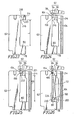
- Figs. 9 to 12 which show a second preferred embodiment intending to reduce such a stress concentration in the first preferred embodiment and improve the durability of the leaf springs.
- the same or like parts as in the first preferred embodiment are designated by the same reference numerals, and the related explanation will be omitted thereinafter.
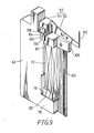
- a second leaf spring 156 fixed to the movable member 82 is adapted to be displaced in parallel to a first leaf spring 154 fixed to the frame 62 upon expansion of the piezoelectric element 72, resulting in rolling of the rolling member 92.
- the leaf springs 154 and 156 are constructed in such a manner that a sectional area in a direction perpendicular to the displacement direction is reduced at an intermediate position of the displacement direction. That is, as clearly shown in Figs. 11 and 12, the first and second leaf springs 154 and 156 are formed on their side surfaces opposite to the facing surfaces with sectional U-shaped grooves 158 and 160 extending across the width W of the leaf springs, respectively.
- the first leaf spring 154 has a large sectional area at the fixed portions fixed to the frame 62 and the rolling member 92, but has a small sectional area at the thin-walled portion 162, namely, at the elastically deformable portion.
- the second leaf spring 156 also has a large sectional area at the fixed portions fixed to the movable member 82 and the rolling member 92, but has a small sectional area at the thin-walled portion 164.
- the first leaf spring 154 is formed on its outer side surface with three U-shaped grooves 166, 168 and 170 extending across the width of the leaf spring 154 and arranged in uniformly spaced relationship from each other in the displacement direction of the leaf spring 154.
- the central groove 168 has a depth greater than the other grooves 166 and 170.
- the second leaf spring 156 is formed on its side surface opposite to the outer side surface of the first leaf spring 154 with three U-shaped grooves 172, 174 and 176 similar to the U-shaped grooves 166, 168 and 170.
- the stress is prevented from being concentrated at the thin-walled portions corresponding to the central deep grooves 168 and 174, and may be dispersed to the other thin-walled portions corresponding to the shallow grooves 166, 170, 172 and 176.
- the first leaf spring 154 is formed on its outer side surface with a pair of U-shaped grooves 178 and 180 extending across the width of the leaf spring 154 and arranged in given spaced relationship from each other in the displacement direction of the leaf spring 154.
- the grooves 178 and 180 have the same width and depth.
- the second leaf spring 156 is formed on its side surface opposite to the outer side surface of the first leaf spring 154 with a pair of U-shaped grooves 182 and 184 similar to the grooves 178 and 180. With this arrangement, the stress is substantially uniformly dispersed to the thin-walled portions formed between the grooves 178, 182 and 180, 184.
- first and second leaf springs 154 and 156 have a uniform thickness, but have a reduced width at their intermediate portions 186. Further, each leaf spring 154(156) is formed at its upper and lower fixed ends with recesses 188 and 190 to be engaged with projections 194 of the base portion 94 of the rolling member 92 and projections 192 and 196 of the frame 62 and the movable member 82, respectively. With this arrangement, the first and second leaf springs 154 and 156 are positioned at their fixed end portions to the groove 98 of the rolling member 92, the mounting surface 88 of the frame 62 and the mounting surface 90 of the movable member 82, and are fixed by brazing thereto. Further, as each leaf spring has the intermediate small-width portions 186, the stress may be prevented from being concentrated at the fixed edge of each leaf spring.
- the first and second leaf springs 84 and 86 or 154 and 156 are so arranged as to extend in parallel to the displacement direction of the piezoelectric element 72 under the condition where the facing surfaces of each leaf spring are in contact with each other.
- the movable member 82 Upon expansion of the piezoelectric element 72, the movable member 82 is displaced to upwardly move the leaf spring 86(156) fixed to the movable member 82 in such a manner as to slidingly contact the leaf spring 84(154) fixed to the frame 62.
- both the leaf springs 84 and 86 (154 and 156) are elastically deformed.
- the leaf springs 84 and 86 are installed into the groove 98 of the base portion 94 of the rolling member 92 in such a manner that the lower ends of the leaf springs tend to be curved outwardly. Further, the leaf spring 86(156) is fixed to one side surface of the movable member 82. As a result, it was realized in the experiment that the deformable portions of the leaf springs are wavingly slid with a large frictional force, causing a possibility of wear or seizure of the leaf springs.
- Figs. 16 to 22 show a third preferred embodiment intended to reduce such large friction at the deformable portions of the leaf springs contacting with each other and thereby prevent the wear or seizure of the leaf springs.
- a pair of upper and lower wedge members 198 and 200 are interposed between the lower end surface of the piezoelectric element 72 and the upper end surface of the base portion 78 of the frame 62.
- Both the wedge members 198 and 200 are formed of a material such as zinc having a linear expansion characteristic contrary to that of the piezoelectric element 72, so that the expansion and contraction of the piezoelectric element 72 due to a temperature change may be compensated by the contraction and expansion of the wedge members 198 and 200 to thereby maintain constant the height of the piezoelectric element 72 from the upper end surface of the base portion 78 of the frame 62.
- first and second leaf springs 204 and 206 contacting with each other are formed with U-shaped grooves 158 and 160 to form thin-walled portions (deformable portions) 162 and 164, respectively.
- the thin-walled portions 162 and 164 are readily deformable.
- the opposed surfaces of the deformable portions 162 and 164 of the leaf springs 204 and 206 are formed with recessed portions 208 and 210 for hindering intercontact between the deformable portions 162 and 164.
- the recessed portions 208 and 210 extend across the width of the leaf springs 204 and 206 on the opposite side of the grooves 158 and 160, thus defining a rectangular cavity between the deformable portions 162 and 164.
- W and t stand for a width and a thickness of the leaf spring, respectively; l and t2 stand for a length and a wall thickness of the deformable portion, respectively; S and l2 stand for a spacing and a length of the cavity defined by the recessed portion; and N and P stand for the natural frequency and the stroke of the wire 50.
- the leaf springs 154 and 156 were used in the test under an initial condition where seizure and wear have not yet been generated.
- the deformable portions 162 and 164 of the leaf springs 204 and 206 shown in Fig. 19 are formed with the recessed portions 208 and 210 defining a cavity with a spacing of 0.2 mm, a frictional force between the facing surfaces of the deformable portions 162 and 164 may be greatly reduced to thereby increase the displacement magnification rate (a percentage of the stroke of the printing wire 50 relative to the expansion quantity of the piezoelectric element 72).
- the seizure and wear to be generated between the facing surfaces of the deformable portions 162 and 164 may be prevented to maintain the increased magnification rate for a long period of time.
- Example 1 the spacing S of the cavity defined by the deformable portions 208 and 210 was set to 0.6 mm, and the length of the cavity was set to 1.0 mm.
- the other dimensions were identical with those of Example shown in Fig. 19.
- Example 2 shown in Fig. 20 the deformable portions 162 and 164 of the leaf springs 204 and 206 have no grooves on opposite side surfaces thereof so as to increase the spacing S of the cavity defined by the recessed portions 208 and 210.
- Example 3 shown in Fig. 21 the structure is similar to that of Example 2 except that a small spacing S2 is defined between the facing surfaces of the leaf springs 204 and 206.
- the U-shaped groove 213 functions as the cavity mentioned in the previous Examples 1 to 3.
- Table 4 shows the comparison among the above Examples 1 to 4.
- Example 1 4.0 0.8 1.0 0.2 0.6 1.0 - 2.4 330
- Example 2 4.0 0.8 1.0 0.27 1.06 1.0 - 4.2 210
- Example 3 4.0 0.6 1.0 0.2 1.0 1.0 0.2 3.5 250
- Example 4 4.0 0.5 1.0 0.2 0.6 - - 2.4 330
- Example 1 and Example 4 As apparent from Tables 3 and 4, the displacement magnification rate in Example shown in Fig. 19, Example 1 and Example 4 is increased in comparison with that in Example shown in Fig. 12.
- Example shown in Fig. 12 the spacing S is reduced to be zero so as to increase the magnification rate in accordance with a principle of lever.
- a load to be applied to the piezoelectric element 72 is increased to suppress the expansion of the piezoelectric element 72, resulting in limitation of the stroke of the printing wire.
- Example shown in Fig. 19 Example 1 and Example 4
- a distance between the center of the thickness of the deformable portion 162 and the center of the thickness of the deformable portion 164 is set to 0.4 - 0.8 mm, so that although the magnification rate is just reduced, the load to be applied to the piezoelectric element 72 is reduced. Accordingly, it is considered that a large stroke of the printing wire could be obtained.
- an increase in the natural frequency contributes to an increase in a return speed of the rolling member 92, resulting in an improvement in a printing speed of the printing head.
- the natural frequencies in Examples 1 and 4 are smaller than those in Examples 2 and 3, Examples 1 and 4 are preferred from the viewpoint of the stroke of the printing wire.
- the frame 62 and the movable member 82 are formed independently.
- the movable member 82 is positioned through the leaf springs 84 and 86 (154 and 156 or 204 and 206) and the connecting member 104 relative to the frame 62, and then the piezoelectric element 72 is fixedly interposed between the movable member 82 and the base portion 78 of the frame 62.
- Figs. 23 to 26 show a method of producing the printing unit which improves the accuracy of dimension and the degree of parallelism between the movable member 82 and the base portion 78 of the frame 62 by way of an example in accordance with the present invention.
- the frame 62 is formed from a rectangular metal plate having a given thickness extending in a direction substantially parallel to the piezoelectric element 72.
- the frame 62 is formed at its lower end portion with the laterally projecting base portion 78 for supporting the lower end of the piezoelectric element 72 through the pair of wedge members 198 and 200.
- the frame 62 is integrally formed at its upper end portion with a movable member 214 connected through a connecting portion 216.
- the movable member 214 is spaced a distance L from the base portion 78 so as to insert the piezoelectric element 72 and the wedge members 198 and 200.
- a recess 218 is defined between the frame 62 and the movable member 214 so as to insert the base portions of the leaf springs 154 and 156 by press working, for example.
- the upper surface 80 of the base portion 78 of the frame 62 and the lower surface 220 of the movable member 214 are finished as required so as to further improve the accuracy of the distance L and the degree of parallelism.
- the upper end portions of the leaf springs 154 and 156 are inserted into the groove 98 of the base member 94 of the rolling member 92, and are fixed by brazing thereto. Then, the base portions of the leaf springs 154 and 156 fixed to the base member 94 are inserted into the recess 218, and are fixed by brazing to the inner wall surface of the recess 218. Under the condition, the leaf springs 154 and 156 are elastically deformably contacted with each other.
- the connecting member 104 adapted to be elastically displaced in a direction parallel to the displacement direction of the piezoelectric element 72 is provided between the movable member 214 and the base portion 78 of the frame 62 in such a manner that the upper end portion of the connecting member 104 is fixed to the side surface of the movable member 214, while the lower end portion is fixed to the side surface of the base portion 78.
- a sectional area at the end portions of the connecting member 104 to be fixed to the movable member 214 and the frame 62 are larger than a sectional area at an intermediate portion between the fixed end portions, by forming three elongated holes at the intermediate portion, so that the connecting member 104 may be more readily expanded and contracted in receipt of the displacement of the piezoelectric element 72.
- a separation slit 222 is formed into the connecting portion 220 from the underside to the bottom of the recess 218, so as to separate the movable member 214 from the frame 62.
- the upper wedge member 198 is fixed to the lower end surface of the piezoelectric element 72 by an adhesive, and they are inserted between the movable member 214 and the base portion 78 of the frame 62 until a stopper surface 226 of the upper wedge member 198 abuts against the side surface of the frame 62, and then the upper end surface of the piezoelectric element 72 abuts against the lower surface of the movable member 214. At this time, the upper end surface of the piezoelectric element 72 is bonded by an adhesive to the lower surface of the movable member 214 as required.
- the lower wedge member 200 is inserted between the upper wedge member 198 and the base portion 78 of the frame 62, and is beat by a give force, thus completing the installation of the piezoelectric element 72.
- the abutting surfaces among the lower wedge member 200, the upper wedge member 198 and the base portion 78 of the frame 62 are coated with an adhesive as required.
- the high accuracy of the distance L (shown in Fig. 25) and the parallelism between the base portion 78 of the frame 62 and the movable member 214 may be ensured. Accordingly, the piezoelectric element 72 and the pair of wedge members 198 and 200 may be closely fitted between the base portion 78 of the frame 62 and the movable member 214, and the movable member 214 may be displaced sufficiently in receipt of the displacement of the piezoelectric element 72.
- both the leaf springs 154 and 156 are elastically deformed sufficiently in receipt of the displacement of the movable member 214 to accurately roll the rolling member 92 at a given angle, thereby ensuring good printing operation.
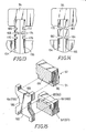
- Figs. 27 and 28 which show a modification of the preferred embodiment shown in Figs. 23 to 26, wherein a single thick leaf spring 212 is formed with a central split groove 213 extending from the separation groove 222 formed at the connecting portion 216.
- the printing unit in this case is manufactured in the following manner. That is, as shown in Fig. 27, the movable member 214 is integrally formed at one end of the frame 62 through the connecting portion 216. Then, the single thick leaf spring 212 fixed to the rolling member 92 is inserted into the recess 218 formed between the frame 62 and the movable member 214, and is fixed by brazing to the recess 218.
- the separation groove 222 is formed in the connecting portion to separate the movable member 214 from the frame 62. Further, the central split groove 213 is formed in the single leaf spring 212 in such a manner as to extend from the separation groove 222, thereby forming a pair of leaf spring members 204 and 206.
- the high accuracy of the distance and the parallelism between the movable member 214 and the base portion 78 of the frame 62 can be obtained. Moreover, since the single leaf spring 212 is used, the number of parts may be reduced.
- the rolling member 92 is so fixed as to ride over the end portions of the pair of leaf springs.
- the upper end portions of the leaf springs 154 and 156 are fixed in the recess 98 of the base member 94 of the rolling member 92, and the lower end portions are fixed to the movable member 82 and the frame 62.
- the deformation of the leaf springs 154 and 156 on the base member 94 side is greater than that on the frame 62 and the movable member 82 side, and a brazed portion A on the inner surface of the recess 98 is subject to a repeated tensile load and compression load. Thereafter, there is a possibility of cracks being generated at the brazed portion A. If the cracks were generated, the leaf springs 154 and 156 would be eventually separated from the base member 94 of the rolling member 92.
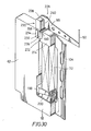
- the following preferred embodiment as shown in Figs. 30 and 31 is intended to prevent the generation of cracks at the fixing portion between the leaf springs and the rolling member and thereby improve the durability, and also to reduce the number of parts and thereby simplify the structure.
- a single thick spring member 230 is formed with a central split groove 232 to thereby form a pair of leaf springs 234 and 236. Further, a head portion connecting the leaf springs 234 and 236 functions as a rolling base member 238. That is, the pair of split plate portions of the spring member 230 function as the leaf springs 234 and 236, while the head portion of the spring member 230 functions as the rolling base member 238. In other words, the leaf springs 234 and 236 are integrally formed with the rolling base member 238 with no fixed portions.
- the leaf springs 234 and 236 are fixed by brazing to the spring mounting surfaces 88 and 90 of the frame 62 and the movable member 214. Further, the leaf springs 234 and 236 are formed at their intermediate positions with opposite U-shaped grooves 158 and 160 at which portions the leaf springs are mainly elastically deformed.
- the head portion 238 is formed with a recess 240 for receiving the wire driving arm 96 of the rolling member 228.
- the base end portion of the wire driving arm 96 is inserted into the recess 240, and is fixed by brazing to the recess 240.
- the printing wire 50 is also fixed by brazing to the tip of the wire driving arm 96.
- the frame 62 is formed independently of the movable member 214.
- Fig. 32 shows a modification of the preferred embodiment shown in Figs. 30 and 31.
- the movable member 214 is integrally formed with the frame 62, so that the high accuracy of the distance L and the parallelism between the base portion of the frame 62 and the movable member 214 may be readily attained.
- the separation groove 222 is formed in the connecting portion 216 to separate the frame 62 and the movable member 214.
- the central split groove 232 is formed in the spring member 230 in such a manner as to extend from the separation groove 222.
- the pair of leaf springs 234 and 236 and the rolling base member 238 are integrally formed by the single spring member 230, there is no necessity for fixing (brazing) both the members, resulting in no possibility of the generation of cracks at the brazed portion, thus improving the durability. In addition, the number of parts may be reduced.
- a spring member 242 is bent in the form of a U-shape to form the pair of leaf springs 234 and 236.
- a bent portion or a head portion of the spring member 242 is fixed to a base portion 244 (corresponding to the rolling base member) of the rolling member 228 by welding or brazing.
- the elastically deformable connecting member 104 between the movable member 82 (as in Fig. 10, for example) and the base portion 78 of the frame, so as to maintain parallel displacement of the movable member 82 in receipt of the displacement of the piezoelectric element 72 and thereby prevent lack of the rolling angle of the rolling member 92.
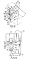
- the following preferred embodiment as shown in Figs. 34 through 38 intends to prevent the inclination of the movable member 82 more reliably by providing a parallel link mechanism between the movable member 82 and the frame 62.
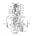
- a parallel link mechanism 246 is provided.
- the parallel link mechanism 246 is provided between the frame 62 and the movable member 82 so as to guide the movable member 82 under the condition parallel to the displacement direction of the piezoelectric element 72.
- the parallel link mechanism 246 is formed from an elastically deformable single plate by punching and bending, thus forming a pair of parallel link plates 248 having the same shape and a connecting portion 250 connecting both the link plates 248.
- Each of the pair of link plates 248 includes a pair of parallel vertical link portions 252 and 254, a pair of parallel horizontal link portions 264 and 266 and four elastically deformable hinge portions 256, 258, 260 and 262 connecting the vertical link portions 252 and 254 with the horizontal link portions 264 and 266.
- the link plate 248 forms a quadri-hinged parallel link.
- the opposed inner surfaces of the left vertical link portions 252 of the link plates 248 are fixed by brazing to both the side surfaces of the frame 62, while the opposed inner surfaces of the right vertical link portions 254 are fixed by brazing to both the side surfaces of the movable member 82 at its intermediate portion. Further, the inner surface of the connecting portion 250 of the link mechanism 246 is fixed to the upper surface of the movable member 82.
- the piezoelectric element 72 In operation, when the piezoelectric element 72 is supplied with voltage, it is expanded by a predetermined length in the direction of the arrow X shown in Fig. 35 to displace the movable member 82 against the load of the connecting member 104, the second leaf spring 156 and the parallel link mechanism 246. Then, the second leaf spring 156 is lifted along the first leaf spring 154 by the displacement force of the movable member 82. As a result, both the leaf springs 154 and 156 are curved like a bimetal to generate a moment in the direction of the arrow P shown in Fig. 35. Accordingly, the rolling member 92 is rolled to advance the printing wire 50. To the contrary, when the voltage applied to the piezoelectric element 72 is removed, the piezoelectric element 72 is contracted to follow the displacement of the movable member 82 and thereby return the rolling member 92 and the printing wire 50 to their original position.
- the inclination of the movable member 82 due to the load of the leaf spring 156 is suppressed by the connecting member 104 connected to the movable member 82, and it is further suppressed by the parallel link mechanism 246 so fixed as to ride over the movable member 82 and the frame 62. That is, the movement of the movable member 82 is restricted by the link plates 248, and is guided under the condition parallel to the displacement direction of the piezoelectric element 72. Accordingly, it is possible to eliminate lack of elastic deformation of the leaf springs 154 and 156 due to the inclination of the movable member 82, thereby providing a sufficient stroke of the printing wire 50.
- the leaf springs 154 and 156 are formed with grooves 158 and 160 to form thin-walled deformable portions similar to the previous preferred embodiments. Additionally, the leaf springs 154 and 156 are formed with upper small grooves 268a and lower small grooves 268b, so as to ensure brazing. That is, upon brazing, rod-like brazing members are inserted into the small grooves 268a and 268b, and the same molten by application of heat is penetrated into a small gap between the contact surfaces among the leaf springs, the movable member and the frame. Then, the brazing material is hardened to complete the brazing.
- the horizontal link portions 264 and 266 have a length greater than that in the previous preferred embodiment shown in Figs. 34 to 36, and the other construction is similar to the previous preferred embodiment.
- the displacement of the movable member 82 may be made near a linear displacement in parallel to the displacement of the piezoelectric element 72.
- the pair of leaf springs 234 and 236 are formed from a single thick spring member 230 by defining the split groove 232, and the head portion of the spring member 230 forms the rolling base member 238 to be fixed to the wire driving arm 96.
- This construction is substantially the same as that shown in Fig. 30.
- Reference numeral 272 designates a parallel link mechanism in this modification.
- the vertical link portions 252 and 254 extend a fixed length upward from the upper surfaces of the frame 62 and the movable member 82.
- the vertical link portions 252 are fixed at their lower portion to both the side surfaces of the frame 62, and are integrally connected at their upper portion with each other by a connecting portion 250.
- the parallel link mechanism 272 shown in Fig. 38 is located in such a manner that the horizontal link portions 264 and 266 ride over the leaf springs 234 and 236, and the distance between the horizontal link portions 264 and 266 is increased.
- the movable member 82 may be more stably displaced in parallel to the displacement direction of the piezoelectric element 72.
- the connecting member 104 may be removed when suitably setting an elastic force of the hinge portions of the parallel link mechanism owing to the elasticity of the hinge portions.
- the quick return operation of the movable member 82 and the rolling member 92 may be ensured, and the parallel displacement of the movable member 82 in relation to the piezoelectric element 72 may be also ensured.
Landscapes
- Engineering & Computer Science (AREA)
- Manufacturing & Machinery (AREA)
- Impact Printers (AREA)
Applications Claiming Priority (16)
| Application Number | Priority Date | Filing Date | Title |
|---|---|---|---|
| JP143530/87 | 1987-06-09 | ||
| JP62143530A JP2550583B2 (ja) | 1987-06-09 | 1987-06-09 | 圧電素子の運動変換機構 |
| JP9083487U JPS63198541U (fr) | 1987-06-12 | 1987-06-12 | |
| JP90834/87U | 1987-06-12 | ||
| JP62149535A JPS63312852A (ja) | 1987-06-16 | 1987-06-16 | 圧電素子駆動型インパクト印字ヘッド |
| JP149535/87 | 1987-06-16 | ||
| JP277169/87 | 1987-10-30 | ||
| JP62277169A JP2775739B2 (ja) | 1987-10-30 | 1987-10-30 | 運動変換機構 |
| JP13229/88 | 1988-01-23 | ||
| JP63013229A JP2555666B2 (ja) | 1988-01-23 | 1988-01-23 | 圧電素子を用いた運動変換機構の製造方法 |
| JP63014019A JP2555667B2 (ja) | 1988-01-25 | 1988-01-25 | 圧電素子の運動変換装置 |
| JP14019/88 | 1988-01-25 | ||
| JP19844/88 | 1988-01-29 | ||
| JP63019844A JP2556081B2 (ja) | 1988-01-29 | 1988-01-29 | 圧電素子の運動変換装置 |
| JP63023561A JP2555670B2 (ja) | 1988-02-02 | 1988-02-02 | 圧電素子の運動変換機構 |
| JP23561/88 | 1988-02-02 |
Publications (3)
| Publication Number | Publication Date |
|---|---|
| EP0295102A2 true EP0295102A2 (fr) | 1988-12-14 |
| EP0295102A3 EP0295102A3 (en) | 1990-06-13 |
| EP0295102B1 EP0295102B1 (fr) | 1993-09-22 |
Family
ID=27571733
Family Applications (1)
| Application Number | Title | Priority Date | Filing Date |
|---|---|---|---|
| EP88305280A Expired - Lifetime EP0295102B1 (fr) | 1987-06-09 | 1988-06-09 | Dispositif pour renforcer le déplacement d'un élément piézoélectrique ou d'un élément semblable |
Country Status (3)
| Country | Link |
|---|---|
| US (2) | US4874978A (fr) |
| EP (1) | EP0295102B1 (fr) |
| DE (1) | DE3884281T2 (fr) |
Cited By (6)
| Publication number | Priority date | Publication date | Assignee | Title |
|---|---|---|---|---|
| EP0409224A1 (fr) * | 1989-07-20 | 1991-01-23 | Fujitsu Limited | Mécanisme pour renforcer le déplacement, par exemple pour un élément d'impression |
| EP0416551A3 (en) * | 1989-09-05 | 1991-08-21 | Brother Kogyo Kabushiki Kaisha | Device for magnifying displacement of piezoelectric element and method of producing the same |
| EP0407184A3 (en) * | 1989-07-06 | 1991-08-21 | Brother Kogyo Kabushiki Kaisha | Parallel link mechanism |
| GB2245097B (en) * | 1990-03-06 | 1993-09-15 | Brother Ind Ltd | Longitudinal-effect type laminar piezoelectric/electrostrictive driver,and printing actuator using the driver |
| GB2270038B (en) * | 1992-08-18 | 1997-03-26 | Fujitsu Ltd | Electromechanical actuators for use in wire-dot printing heads |
| EP0756938A3 (fr) * | 1992-05-08 | 1998-01-14 | Fujitsu Limited | Tête d'impression |
Families Citing this family (22)
| Publication number | Priority date | Publication date | Assignee | Title |
|---|---|---|---|---|
| US5028834A (en) * | 1988-07-21 | 1991-07-02 | Brother Kogyo Kabushiki Kaisha | Device for magnifying displacement of piezoelectric element and method of producing same |
| US5165809A (en) * | 1990-03-06 | 1992-11-24 | Brother Kogyo Kabushiki Kaisha | Piezoelectric actuator and print head using the actuator, having means for increasing durability of laminar piezoelectric driver |
| US5133612A (en) * | 1990-10-03 | 1992-07-28 | Brother Kogyo Kabushiki Kaisha | Dot impact type printing head with adhesively attached base unit |
| JPH04102849U (ja) * | 1991-02-08 | 1992-09-04 | ブラザー工業株式会社 | 印字ヘツド |
| JPH05147237A (ja) * | 1991-11-18 | 1993-06-15 | Fujitsu Ltd | 印字ヘツド |
| US5903085A (en) * | 1997-06-18 | 1999-05-11 | Phase Metrics, Inc. | Piezoelectric nanopositioner |
| US6548938B2 (en) | 2000-04-18 | 2003-04-15 | Viking Technologies, L.C. | Apparatus having a pair of opposing surfaces driven by a piezoelectric actuator |
| US6717332B2 (en) | 2000-04-18 | 2004-04-06 | Viking Technologies, L.C. | Apparatus having a support structure and actuator |
| US6759790B1 (en) * | 2001-01-29 | 2004-07-06 | Viking Technologies, L.C. | Apparatus for moving folded-back arms having a pair of opposing surfaces in response to an electrical activation |
| US6879087B2 (en) | 2002-02-06 | 2005-04-12 | Viking Technologies, L.C. | Apparatus for moving a pair of opposing surfaces in response to an electrical activation |
| USD494923S1 (en) | 2002-06-19 | 2004-08-24 | Viking Technologies, L.C. | Integral force transfer member |
| USD493416S1 (en) | 2002-06-19 | 2004-07-27 | Viking Technologies, L.C. | Integral actuator with force transfer member |
| USD483335S1 (en) | 2002-06-19 | 2003-12-09 | Viking Technologies, L.C. | Integral actuator with folded-back arms |
| USD496330S1 (en) | 2002-12-10 | 2004-09-21 | Viking Technologies, L.C. | Integral actuator with hollowed out force transfer member |
| USD493135S1 (en) | 2002-12-10 | 2004-07-20 | Viking Technologies, L.C. | Integral actuator with folded back arms and hollowed out force transfer member |
| USD493417S1 (en) | 2002-12-10 | 2004-07-27 | Viking Technologies, L.C. | Folded back arm actuator |
| CA2521307C (fr) | 2003-04-04 | 2014-07-15 | Viking Technologies, L.C. | Appareil et processus d'optimisation du travail a partir d'un dispositif de commande materiel intelligent |
| USD512085S1 (en) | 2003-06-06 | 2005-11-29 | Viking Technologies, L.C. | Folded back arm actuator with enlarged central anvil |
| US20060214284A1 (en) * | 2005-03-24 | 2006-09-28 | Stuart Haden | Apparatus and method for data capture |
| JP4511437B2 (ja) * | 2005-09-09 | 2010-07-28 | Necトーキン株式会社 | 音響信号発生用圧電装置 |
| AU2009301643B2 (en) * | 2008-10-09 | 2014-09-04 | Elektron Technology Uk Limited | A positioning system and method |
| DE102016108690A1 (de) * | 2016-05-11 | 2017-11-16 | Lofelt Gmbh | Vibrierender Aktor |
Family Cites Families (13)
| Publication number | Priority date | Publication date | Assignee | Title |
|---|---|---|---|---|
| GB1193503A (en) * | 1967-03-10 | 1970-06-03 | Int Computers Ltd | Actuators |
| US3614486A (en) * | 1969-11-10 | 1971-10-19 | Physics Int Co | Lever motion multiplier driven by electroexpansive material |
| US3649857A (en) * | 1970-07-30 | 1972-03-14 | Ibm | Mechanical energy storage and release device |
| US3955049A (en) * | 1974-12-04 | 1976-05-04 | Florida Data Corporation | Printing head |
| JPS57187980A (en) * | 1981-05-14 | 1982-11-18 | Nec Corp | Rotation movement generating mechanism |
| US4435666A (en) * | 1981-05-26 | 1984-03-06 | Nippon Electric Co., Ltd. | Lever actuator comprising a longitudinal-effect electroexpansive transducer and designed to prevent actuation from degrading the actuator |
| DE3367558D1 (en) * | 1982-08-05 | 1987-01-02 | Nec Corp | Impact printer head capable of printing a dot at a distance narrower than a thickness of a printer unit |
| US4547086A (en) * | 1982-12-06 | 1985-10-15 | Nec Corporation | Piezoelectrically driven printing mechanism for dot matrix printers |
| CA1218561A (fr) * | 1983-02-25 | 1987-03-03 | Takeshi Yano | Commande mecanique differentielle a bras, avec segments de transmission de l'effort peu susceptibles de se rompre |
| JPS6081568A (ja) * | 1983-10-11 | 1985-05-09 | Nec Corp | 機械的増幅機構 |
| US4675568A (en) * | 1984-08-13 | 1987-06-23 | Nec Corporation | Mechanical amplification mechanism for electromechanical transducer |
| DE3681927D1 (de) * | 1985-01-21 | 1991-11-21 | Nec Corp | Piezoelektrische bistabile betaetigungsvorrichtung mit einem projektil das einen stoss empfaengt. |
| CA1319295C (fr) * | 1988-03-18 | 1993-06-22 | Akio Yano | Tete d'imprimante a mosaique |
-
1988
- 1988-06-03 US US07/202,035 patent/US4874978A/en not_active Ceased
- 1988-06-09 EP EP88305280A patent/EP0295102B1/fr not_active Expired - Lifetime
- 1988-06-09 DE DE88305280T patent/DE3884281T2/de not_active Expired - Lifetime
-
1991
- 1991-10-17 US US07/780,099 patent/USRE34823E/en not_active Expired - Lifetime
Cited By (9)
| Publication number | Priority date | Publication date | Assignee | Title |
|---|---|---|---|---|
| EP0407184A3 (en) * | 1989-07-06 | 1991-08-21 | Brother Kogyo Kabushiki Kaisha | Parallel link mechanism |
| EP0409224A1 (fr) * | 1989-07-20 | 1991-01-23 | Fujitsu Limited | Mécanisme pour renforcer le déplacement, par exemple pour un élément d'impression |
| US5184901A (en) * | 1989-07-20 | 1993-02-09 | Fujitsu Ltd. | Displacement magnifying mechanism for a print element |
| EP0416551A3 (en) * | 1989-09-05 | 1991-08-21 | Brother Kogyo Kabushiki Kaisha | Device for magnifying displacement of piezoelectric element and method of producing the same |
| US5111101A (en) * | 1989-09-05 | 1992-05-05 | Brother Kogyo Kabushiki Kaisha | Device for magnifying displacement of piezoelectric element and method of producing the same |
| GB2245097B (en) * | 1990-03-06 | 1993-09-15 | Brother Ind Ltd | Longitudinal-effect type laminar piezoelectric/electrostrictive driver,and printing actuator using the driver |
| EP0756938A3 (fr) * | 1992-05-08 | 1998-01-14 | Fujitsu Limited | Tête d'impression |
| GB2270038B (en) * | 1992-08-18 | 1997-03-26 | Fujitsu Ltd | Electromechanical actuators for use in wire-dot printing heads |
| US5726521A (en) * | 1992-08-18 | 1998-03-10 | Fujitsu Limited | Electromechanical actuator used in wire-dot printing head |
Also Published As
| Publication number | Publication date |
|---|---|
| USRE34823E (en) | 1995-01-10 |
| EP0295102B1 (fr) | 1993-09-22 |
| DE3884281T2 (de) | 1994-02-17 |
| US4874978A (en) | 1989-10-17 |
| DE3884281D1 (de) | 1993-10-28 |
| EP0295102A3 (en) | 1990-06-13 |
Similar Documents
| Publication | Publication Date | Title |
|---|---|---|
| EP0295102A2 (fr) | Dispositif pour renforcer le déplacement d'un élément piézoélectrique ou d'un élément semblable | |
| US4979275A (en) | Device for magnifying displacement of piezoelectric element or the like and method for producing same | |
| US5028834A (en) | Device for magnifying displacement of piezoelectric element and method of producing same | |
| US4675568A (en) | Mechanical amplification mechanism for electromechanical transducer | |
| EP0065784B1 (fr) | Système d'entraînement à levier ayant un transducteur à effet longitudinal électroexpansif construit de facon à empêcher des mouvements dégradant le système d'entraînement | |
| KR920000390B1 (ko) | 와이어-돗트 충격식 프린터의 인쇄헤드 | |
| EP0101018B1 (fr) | Tête d'impression à impact pouvant imprimer des points à une distance inférieure à la largeur d'un élément d'imprimante | |
| US5596242A (en) | Guide device for vibration driven motor | |
| US5111101A (en) | Device for magnifying displacement of piezoelectric element and method of producing the same | |
| JP2775739B2 (ja) | 運動変換機構 | |
| US4547089A (en) | Guide for a print head of a printing device | |
| CN116633191A (zh) | 行走式压电致动位移装置及装配方法 | |
| US5292201A (en) | Printing head of wire-dot impact printer | |
| US5219235A (en) | Dot line printer having improved yoke assembly | |
| JPS5926273A (ja) | インパクト印字ヘッド | |
| JP2550583B2 (ja) | 圧電素子の運動変換機構 | |
| JPH03288662A (ja) | 圧電素子の運動変換装置における圧電素子の組付け方法 | |
| JP2590947B2 (ja) | 圧電素子の変位変換装置 | |
| EP0569253B1 (fr) | Tête d'impression | |
| JP2556081B2 (ja) | 圧電素子の運動変換装置 | |
| JP2555666B2 (ja) | 圧電素子を用いた運動変換機構の製造方法 | |
| JPH0434039Y2 (fr) | ||
| CN120487758A (zh) | 一种柔性铰链以及半导体定位设备 | |
| JPH0276272A (ja) | 圧電素子の運動変換装置 | |
| JP2555667B2 (ja) | 圧電素子の運動変換装置 |
Legal Events
| Date | Code | Title | Description |
|---|---|---|---|
| PUAI | Public reference made under article 153(3) epc to a published international application that has entered the european phase |
Free format text: ORIGINAL CODE: 0009012 |
|
| AK | Designated contracting states |
Kind code of ref document: A2 Designated state(s): DE FR GB IT |
|
| PUAL | Search report despatched |
Free format text: ORIGINAL CODE: 0009013 |
|
| RHK1 | Main classification (correction) |
Ipc: B41J 7/80 |
|
| AK | Designated contracting states |
Kind code of ref document: A3 Designated state(s): DE FR GB IT |
|
| 17P | Request for examination filed |
Effective date: 19900618 |
|
| 17Q | First examination report despatched |
Effective date: 19920221 |
|
| GRAA | (expected) grant |
Free format text: ORIGINAL CODE: 0009210 |
|
| AK | Designated contracting states |
Kind code of ref document: B1 Designated state(s): DE FR GB IT |
|
| PG25 | Lapsed in a contracting state [announced via postgrant information from national office to epo] |
Ref country code: IT Free format text: LAPSE BECAUSE OF FAILURE TO SUBMIT A TRANSLATION OF THE DESCRIPTION OR TO PAY THE FEE WITHIN THE PRESCRIBED TIME-LIMIT;WARNING: LAPSES OF ITALIAN PATENTS WITH EFFECTIVE DATE BEFORE 2007 MAY HAVE OCCURRED AT ANY TIME BEFORE 2007. THE CORRECT EFFECTIVE DATE MAY BE DIFFERENT FROM THE ONE RECORDED. Effective date: 19930922 Ref country code: FR Effective date: 19930922 |
|
| REF | Corresponds to: |
Ref document number: 3884281 Country of ref document: DE Date of ref document: 19931028 |
|
| EN | Fr: translation not filed | ||
| PLBE | No opposition filed within time limit |
Free format text: ORIGINAL CODE: 0009261 |
|
| STAA | Information on the status of an ep patent application or granted ep patent |
Free format text: STATUS: NO OPPOSITION FILED WITHIN TIME LIMIT |
|
| 26N | No opposition filed | ||
| REG | Reference to a national code |
Ref country code: GB Ref legal event code: IF02 |
|
| PGFP | Annual fee paid to national office [announced via postgrant information from national office to epo] |
Ref country code: DE Payment date: 20070607 Year of fee payment: 20 |
|
| PGFP | Annual fee paid to national office [announced via postgrant information from national office to epo] |
Ref country code: GB Payment date: 20070606 Year of fee payment: 20 |
|
| REG | Reference to a national code |
Ref country code: GB Ref legal event code: PE20 Expiry date: 20080608 |
|
| PG25 | Lapsed in a contracting state [announced via postgrant information from national office to epo] |
Ref country code: GB Free format text: LAPSE BECAUSE OF EXPIRATION OF PROTECTION Effective date: 20080608 |