EP0295124A2 - Dispositif d'alimentation à vis - Google Patents
Dispositif d'alimentation à vis Download PDFInfo
- Publication number
- EP0295124A2 EP0295124A2 EP19880305323 EP88305323A EP0295124A2 EP 0295124 A2 EP0295124 A2 EP 0295124A2 EP 19880305323 EP19880305323 EP 19880305323 EP 88305323 A EP88305323 A EP 88305323A EP 0295124 A2 EP0295124 A2 EP 0295124A2
- Authority
- EP
- European Patent Office
- Prior art keywords
- funnel
- auger
- shaft
- metering cylinder
- frame
- Prior art date
- Legal status (The legal status is an assumption and is not a legal conclusion. Google has not performed a legal analysis and makes no representation as to the accuracy of the status listed.)
- Ceased
Links
- 239000002245 particle Substances 0.000 claims abstract description 13
- 239000000843 powder Substances 0.000 claims description 62
- 230000008093 supporting effect Effects 0.000 claims description 9
- 230000005484 gravity Effects 0.000 claims description 3
- 238000007599 discharging Methods 0.000 claims description 2
- 238000001514 detection method Methods 0.000 abstract description 6
- 239000003814 drug Substances 0.000 abstract description 6
- 230000001954 sterilising effect Effects 0.000 abstract description 6
- 229940079593 drug Drugs 0.000 abstract 1
- 238000004659 sterilization and disinfection Methods 0.000 abstract 1
- 239000000463 material Substances 0.000 description 11
- 238000010276 construction Methods 0.000 description 9
- 230000002093 peripheral effect Effects 0.000 description 8
- 238000005303 weighing Methods 0.000 description 6
- 239000004020 conductor Substances 0.000 description 5
- 230000007246 mechanism Effects 0.000 description 5
- 230000004048 modification Effects 0.000 description 4
- 238000012986 modification Methods 0.000 description 4
- 238000002347 injection Methods 0.000 description 3
- 239000007924 injection Substances 0.000 description 3
- 238000000034 method Methods 0.000 description 3
- 238000002156 mixing Methods 0.000 description 3
- 230000008569 process Effects 0.000 description 3
- 239000007787 solid Substances 0.000 description 3
- 241001052209 Cylinder Species 0.000 description 2
- 239000000428 dust Substances 0.000 description 2
- 239000000945 filler Substances 0.000 description 2
- 239000011810 insulating material Substances 0.000 description 2
- 238000005192 partition Methods 0.000 description 2
- 238000003756 stirring Methods 0.000 description 2
- 230000004308 accommodation Effects 0.000 description 1
- 230000004323 axial length Effects 0.000 description 1
- 230000005540 biological transmission Effects 0.000 description 1
- 230000000903 blocking effect Effects 0.000 description 1
- 239000013043 chemical agent Substances 0.000 description 1
- 238000004140 cleaning Methods 0.000 description 1
- 230000000052 comparative effect Effects 0.000 description 1
- 238000010586 diagram Methods 0.000 description 1
- 230000000694 effects Effects 0.000 description 1
- 238000005530 etching Methods 0.000 description 1
- 238000002474 experimental method Methods 0.000 description 1
- 239000008187 granular material Substances 0.000 description 1
- 238000009413 insulation Methods 0.000 description 1
- 238000009940 knitting Methods 0.000 description 1
- 239000000203 mixture Substances 0.000 description 1
- 230000002265 prevention Effects 0.000 description 1
- 230000000717 retained effect Effects 0.000 description 1
- 238000007789 sealing Methods 0.000 description 1
Images


Classifications
-
- B—PERFORMING OPERATIONS; TRANSPORTING
- B65—CONVEYING; PACKING; STORING; HANDLING THIN OR FILAMENTARY MATERIAL
- B65B—MACHINES, APPARATUS OR DEVICES FOR, OR METHODS OF, PACKAGING ARTICLES OR MATERIALS; UNPACKING
- B65B1/00—Packaging fluent solid material, e.g. powders, granular or loose fibrous material, loose masses of small articles, in individual containers or receptacles, e.g. bags, sacks, boxes, cartons, cans, or jars
- B65B1/04—Methods of, or means for, filling the material into the containers or receptacles
- B65B1/10—Methods of, or means for, filling the material into the containers or receptacles by rotary feeders
- B65B1/12—Methods of, or means for, filling the material into the containers or receptacles by rotary feeders of screw type
Definitions
- the present invention generally relates to an auger feeder, wherein powder within a cylinder is metered and discharged in accordance with the rotation angle of a screw rotated within the cylinder, to be itemized into a given amount of powder to fill containers.
- a cylindrical metering portion is provided on the lower end portion of a funnel (so-called hopper) for throwing in the powder, a rotary shaft is inserted downwards from above into the funnel, and an auger screw which is loosely engaged within the cylindrical metering portion is secured to the lower end of the rotary shaft.
- the given amount of powder is rendered to fill into a container through a resistor provided at the lower-end opening in accordance with the rotating angle of the screw.
- the above-described auger feeder is used to itemize a comparative large capacity of granule of 10 grams, 100 grams and so on to fill the containers.
- rotary mechanism for an auger screw, funnel for accommodating the weighed thing such as powder or the like are secured as one component of the filler, so that they are adapted not to be dismantled or assembled easily.
- strict consideration is not taken about the mixing prevention of foreign matters such as dusts in the operation step with respect to the weighed powders.
- mixtures of foreign materials such as dusts are required to be completely removed in a step from a process of throwing in the powder to be funnel to a process of itemizing and filling the powder into vials. Consideration is required not to allow the foreign materials, such as dusts, floating in the air or falling from the friction portion of the machine to be mixed with the weighed powder. In the conventional auger feeder, however, this kind of consideration is not given. Also, in the case of an injectables (the bulk pharmaceutical for injection), normally powder as infinitesimal in amount as, for example, 50 mg in one weighing value is required to be itemized, filled. But conventionally it is difficult to itemize, fill the powder of infinitesimal amount with high accuracy, because one itemizing, filling amount is comparatively large in capacity as described hereinabove.
- a resistance member such as a mesh is provided at an outlet disposed at the lower end of the metering part in order to prevent the natural falling of powdery particles to be metered.
- the resistance member is, for example, consists of a mesh of a cross knitting in a radial configuration.
- a predetermined amount of powdery particles to be fed is as infinitesimal as 10 mg, 50 mg, 100 mg, 500 mg or the like which is less than 1 g.
- the conventional resistance members are not capable of achieving the above-described metering accuracy.
- an object of the present invention is to provide an auger feeder, which is capable of dismantling, assembling, in a container, the members, which come into contact against the metered, such as auger screw, auger shaft, funnel and so on, almost completely removing the mixing operation of the powder with foreign matters such as dusts at the operation process, effecting automatic detections to stop the operation of the auger filler in a case where the foreign materials may be mixed, i.e., where the auger screw has come into contact against the inside face of the metering portion, so that the sanitation may be thoroughly controlled.
- the powder may be filled with high accuracy even if the itemizing fill is infinitesimal in amount.
- an auger feeder wherein a cylindrical metering portion is provided at the tip end portion of a funnel for accommodating in powder, an auger screw which is fixedly coupled to the tip end of the auger shaft to rotate through the operative cooperation of the auger shaft is disposed within the metering portion, powder is weighed, itemized in accordance with the rotary angle of the auger screw to fill containers and so on, characterized in that the other side portion of the auger shaft is coupled detachably to a rotary driving shaft provided on the driving portion through taper splicing, spline engagement or the like, the funnel is mounted detachably with respect to the support means so that the auger shaft which comes into contact against the powder, the auger screw, the funnel and so on may be freely dismantled, engaged with respect to the secured equipments, and in order to detect the contact between the auger screw disposed at the space from the inner wall of the metering portion, and the metering portion,
- a preparing hopper whose lower end extends through into the funnel, is inclined by 60° or more with respect to the horizontal face and has a side face like a conical face surrounding the axial center of the funnel is provided, a two-divided cover which closes the top-face opening portion of the funnel with the exception of the preparing hopper and the auger shaft is provided, a gas feeding entrance for retaining the funnel interior under the positive voltage is provided in the cover of the funnel top face, a solid, gas separator which collects dusts from the air within the funnel to release them is mounted.
- the auger shaft is vertically divided into two so as to detachably couple them
- the funnel is divided into two, upper and lower portions, so as to detachably couple them
- the upper, lower funnels are respectively positioned in supporting means and mounted
- a resisting member which prevents the natural fall of the powder during the auger stop is adapted to be detachably mounted in the lower end opening portion of the weighing portion formed at the tip end of the funnel on the side of the lower portion.
- the auger feeder in accordance with the present invention comprises a metering cylindrical portion provided at the lower end of a funnel which accommodates powder, an auger screw disposed inside the cylindrical portion spaced a predetermined clearance from the inner peripheral face of the cylindrical metering portion in which the powder which has been metered and itemized is fed from the outlet disposed at the lower end of the cylindrical part to a container according to the rotation of the auger screw, and a plate-shaped resistance member, to be mounted on the outlet disposed at the lower end of the cylindrical metering part, composed of an outer peripheral frame portion, straight or curved bridges which partition the interior of the frame, and a plurality of opening portions surrounded by the frame portion and the bridges.
- the present invention has the following function.
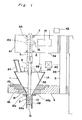
- the auger feeder includes, as major members shown schematically in Fig. 1, a funnel 1, a metering cylinder 2 provided on the lower end portion of the funnel 1, a vertically erected support 3, a bracket 4 for a funnel supporting means projected from the support 3, a rotary driving shaft 5, bearings 6, 7 for rotatably supporting both the upper, lower ends in the frame of the rotary driving shaft 5, an auger shaft 9 composed of an upper shaft 9A and a lower shaft 9B, an auger screw 10 which is fixedly mounted at the lower end of the lower auger shaft 9B and is loosely engaged within the metering cylinder 2, a servo motor 14 for driving the rotary driving shaft 5, a charge hopper which throws powder to be metered and subdivided into the funnel 1, a cover 25 which closes the top-face opening portion of the funnel 1, and a contact detector 40 to be provided between the metering
- the servo motor 14 is provided on one side of a housing 41 accommodating the driving mechanism, while the rotary driving shaft 5 is rotatably supported and is vertically provided, on the other side, by the bearings 6, 7 mounted on the housing upper, lower frames.
- the driving force of the servo motor 14 is transmitted to the rotary driving shaft 5 by a pulley transmission mechanism 15 composed of a belt 15a and a pulley 15b secured to the rotary driving shaft 5.
- the servo motor 14 is controlled by a control unit 42 and is adapted to rotate at the given rotating angle of the rotary driving shaft 5 and come to a stop.
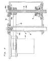
- the rotary driving shaft 5 of a long, cylindrical shape projects downwardly from the housing 41, with the inner peripheral face of the lower side forming a taper portion 5a which becomes larger in inner diameter towards the bottom and a pair of notches 5b being formed opposite to the lower end portion.
- the upper shaft 9A of auger shaft 9 is a little shorter in length than the rotary driving shaft 5, with a mounting head 9A1 on the housing 41 being formed on the top end of the upper shaft 9A, the upper shaft 9A being internally engaged with the rotary driving shaft 5 from above and being mounted on the housing 41.
- a screw portion 9A2 which projects into the taper portion 5a of the rotary driving shaft 5 is provided on the lower portion of the upper shaft 9A.
- the lower shaft 9B of auger shaft 9 has the outer peripheral face of the upper side portion thereof forming a taper portion 9B1 which internally engaged with the taper portion 5a of the rotary driving shaft 5, with a tapped hole 9B2 being drilled in the axial center portion from the top end face and a pair of pins 9B3 being projected from the lower portion of the taper face 9B1.
- the lower shaft 9B has at the upper-portion the taper portion to be spliced with and internally engaged with the taper portion of the rotary driving shaft 5, a topped hole 9B2 to be engaged with the screw portion 9A2 of the upper shaft 9A, and the pair of pins 9B3 to be engaged with the notch 5c of the rotary driving shaft 5.
- the auger shaft 9 may be easily dismantled, assembled, the easier dismantling, assembling operations may be effected with respect to the rotary driving shaft 5 disposed in the housing of the driving portion. Also, as the auger shaft 9 is internally engaged into the driving shaft of long length the eccentricity of the auger shaft may be eliminated.
- the lower shaft 9B is inserted through the cover 25 into the axial-center portion of the funnel 1, the tapped hole 9B4 is drilled in the lower end portion thereof, with the upper-end screw portion 10a of the auger screw 10 being couplingly engaged into the tapped hole 9B4.
- a stirring member 45 as shown in Fig. 3 to stir the powder within the funnel 1 is mounted on the upper portion of the auger screw 10 so as to be rotated integrally with the auger screw 10.
- the construction of the funnel 1 for accommodating the powder to be metered and subdivided is composed of two members of the upper funnel 1A and the lower funnel 1B.
- the inner face is set to be connected into an inversely conical shape.
- the upper and lower funnels 1A, 1B are assembled in such that the upper funnel 1A is detachably secured to the support bracket 4 and the lower funnel 1B is detachably secured connected to the upper funnel 1A.
- a flange 1A which is projected in both side ways is integrally formed on the lower end portion of the upper funnel 1A, and the bottom face of the flange 1A, is shaped in two stages.
- the flange 1A1 is set on the placement portion 4a formed in the stage shape corresponding to the bracket 4 and is fixedly clamped with a bolt 46.
- the stage-shaped flange 1B1 which is projected from both the side portions is integrally formed even in the lower funnel 1B, the flange 1B1 is engaged with the bracket 4 and the upper funnel 1A, is positioned and secured with a bolt 47.
- a screen set 48 forming the metering cylinder 2 is mounted with a bolt 49 on the bottom-face of the lower funnel 1B.
- the screen set 48 has a cylindrical skirt 48a, which has an inner diameter equal in diameter to the hole 1B2 open in the bottom-face axial portion of the lower funnel 1B, and a fixing flange 48b on the top end thereof, with a resistance member 16 being detachably mounted on the lower portion of the cylindrical skirt 48a.
- the auger screw 10 is loosely engaged in the metering cylinder, namely, a gap of the given amount is provided between the outer diameter of the auger screw to be mounted and the inner peripheral face of the cylindrical skirt to allow the internal engagement.
- the resistance member 16 is composed of an outer ring 21 of the outer periphery, a plurality of span strips 22a each bridged over the outer ring 21, a plurality of curved strips 22b each bridged between the span strips and a plurality of opening portions 23 surrounded by elements to be selected from the outer ring, span strips, and curved strips.
- the bottle 19 is carried as far as the given position by a supply conveyer (not shown) in such a manner that when it is detected that the bottle has arrived at its given position, a robot operates to place the bottle 19 in a filling holder to stop at a position where the holder has risen to effect the filling operation.
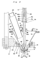
- a charge hopper 24 for feeding the powder to the funnel 1 is fixedly provided on the cover 25 blocking the top-face opening of the funnel 1.
- the bottom portion of the charge hopper 24 is projected from the upper portion within the funnel 1.
- the upper portion of the charge hopper 24 has a side face composed of an inner conical face 26 and an outer conical face 27 surrounding an auger shaft 9, and semi-cylindrical faces 28, 29 connecting both the ends of both the conical faces, with this side face being inclined by 60° or more with respect to the horizontal face.
- the cylindrical supply 51 of small diameter is fixedly projected from the top-side closed face of the charge hopper, and a cover 30 is adapted to be mounted in the supply opening of the cylindrical supply during the supply stop.
- the accommodation volume may be made much larger. Because of steep slope on the side face, the powder bridge is not formed at the inside of the charge hopper 24, thus requiring no vibrator to break the power bridge.
- the cover 25 of a funnel 1 consists of a pair of half-circular plates to be detachably connected with each other to sandwich the auger shaft therebetween, with an auger shaft through-portion 25a being formed in the axial-center of the splicing portion thereof.
- the pair of plates of the cover are detachably mounted in a sealing condition through an O ring 53 on the upper-flange 1A2 of the upper funnel 1A, and are mutually coupled closely with a retaining member (not shown).
- a gas feeding pipe 31 for feeding clean air into the funnel 1 is mounted on the cover 25, and a two-division solid, gas separator 36 is mounted on the outer periphery of the auger shaft through-portion 25a so as to surround the auger shaft 9 for mutual connection.
- the air which has been fed from the gas feeding pipe 31 retains the funnel interior under the positive pressure and is released externally after the dust collection from the solid, gas separator 36, with the funnel lower portion being blocked by the powder.
- the interior of the funnel 1 is retained under the positive pressure in this manner, fine dusts may be prevented from entering into the interior of the funnel 1 from the gaps.
- a contact detecting means to be provided between the funnel 1 and the auger screw 10 will be described.
- a space is provided between the auger screw 10 and the metering cylinder 2. But the foreign matters may be mixed with the powder when they come into contact against each other.
- the detecting means is provided which may detect the filling of foreign matters existing in the powder to remove the fillings at this time.
- the screen set composed of the metering cylinder 2, the funnel 1, the support bracket 4 for securing the funnel 1 are made of a conductive material, and a conductive route to a support 3 for supporting the support bracket 4 is formed to mount a power supply 35 on the support 3.
- all the auger screw 10, the upper and lower shafts 9A, 9B, the rotary driving shaft 5, the support bearing 6 of the rotary driving shaft 5 are made of a conductive material to form the conductive route to the housing 41, with the power supply 34 being mounted on the housing 41.
- An insulating material 13 which electrically insulates is interposed between the housing 41 and the support 3.
- the support 3 and the housing 41 which are respectively connected with the electrodes 34, 35 are connected with a contact detector 40 shown in Fig. 6.
- the contact detector 40 the connection is made to a series circuit of DC power supply 60 and a resistor 37 to input both the ends of the resistor 37 into an operation amplifier 38.
- both the electrodes 34, 35 are insulated by the insulating material 13 during the normal time when the auger screw 10 is not in contact against the weighing portion 2, the potential difference is not caused at both the ends of the resistor 37.
- the operation amplifier 38 detects the potential difference to switch the output lever 1. A warning is issued by the output signal to stop the feeder.
- the detecting means which is not restricted to the embodiment has the housing 41 to the earth, only the side of the support 3 connected with the contact detector 40. If the contact detector 40 is constructed to ground the one terminal to the earth as shown in Fig. 7, the contact between the auger screw 10 and the metering cylinder 2 may be detected as described hereinabove.
- the dismantling operation of the members to which the powder comes into contact is effected in the following order for sterilizing operation.
- Fig. 8, Fig. 9 show an auger feeder in accordance with the second embodiment of the present invention.
- the same members as those of the first embodiment are given the same reference numbers to omit the description.
- a first different point between the second embodiment and the first embodiment is that the auger shaft 9′ is composed of one member without being divided, the upper portion, as a root portion, of the auger shaft is made an outer spline 8′, with the lower side portion extended from the spline 8′ extending through the funnel 1.
- the outer spline 8′ is engaged with an inner spline 5′a formed on the inner peripheral face of the rotary driving shaft 5′ so that the rotating drive force may be transmitted.
- the axial length of the spline 8′ is set five times or more as long as the valley diameter of the spline portion of the auger shaft 9′ to delete the eccentricity of the auger shaft 9′ through the spline engagement.
- the auger shaft 9′ has a screw portion 71 formed at its top end and is supported through clamping operation into the tapped hole 72 formed in the housing 40.
- a semi-division-shaped dust-proof cover 32 is mounted.
- a rotating dust-proof disc 33 is provided within the dust-proof cover 32, so that the falling dusts are adapted to fall down on the outer peripheral portion of the dust-proof cover 32.
- a second different point between the second embodiment and the first embodiment is that the funnel 1′ is integrally found without being divided, with a metering cylinder 2′ being integrally formed in the lower end thereof. Therefore, the resistance member 16 is detachably mounted by a retaining member 17 on the lower end face of the metering cylinder 2′. Also, through a skirt 18 which guides the powder into the bottle 19 is provided on the retaining member 17, the skirt 18 is not always necessary.
- a flange l′a is projected from an approximately central portion of the outer peripheral face, the flange 1′a is placed on a bracket 4′ composed of a support arm extending horizontally from a base plate 3′ vertically erected, is grasped by a stationary plate 74 and is detachably mounted by a bolt 75.
- the second embodiment is somewhat different even in the detection means.
- the bracket 4′ and the support 3′ coupled to the funnel 1 are made of a conductive material, while a horizontal support member 11 for supporting the support bearing 6 of the rotary driving shaft 5 is coupled to the base plate 12 vertically erected, with the base plate 12 and the base plate 3′ being combined with each other through an electric insulating plate 13′.
- Electrodes 34, 35 are mounted on the base plate 3 and the base plate 4, which are connected with contact detector 40.
- the funnel 1 is removed by the releasing operation of the fixation with the bracket 4, thereafter the auger shaft 9′ is removed from the rotary driving shaft 5.
- the engagement may be effected inversely in order.
- the dismantling, engaging operations may be very easily effected.
- the funnel, the cover and the charge hopper, the auger screw, the auger shaft and so on may be easily dismantled, assembled, thus allowing the cleaning, sterilizing operation after removing operation.
- the charge hopper may be made larger in volume even if the funnel is small in size, the number of the supplying operations of the metered material may be reduced, the long hours' operation may be effected with the upward opening portions of the funnel and the hopper being closed.
- the charge hopper does not require an apparatus for preventing bridges from being caused such as vibrator or the like, thus simplifying the apparatus so that the factors for causing the foreign materials are reduced and the weighing accuracy may be improved.
- the auger shaft As the auger shaft is engaged with, at the axial long distance, with the rotary driving shaft, the eccentricity of the auger shaft and the auger screw is eliminated, the contact between the auger screw and the metering cylinder may be prevented, the foreign materials may be prevented from being mixed through the contacting operation.
- the auger screw When the auger screw has come into contact against the metering cylinder, the automatic detection may be made, with the various advantages that bottles with foreign materials being mixed therein may be completely removed.
- the resistance member 16 mounted on the outlet of the metering cylinder 2 as if though closes the outlet has the functions of preventing the natural falling of the powder when the auger screw 10 does not rotate and dropping the powder smoothly when the auger screw 10 is rotating.
- the resistance member 16 is formed as shown in Figs. 11(A) to 11(C) as well as Fig. 4 by a metallic thin plate by subjecting it to, for example, a laser work, a wire cutting, an etching with chemical agent, an electric discharging work, and an ultrasonic work.
- These resistance members 16 have all circular frame, i.e., outer ring 21, and a plurality of span strips 22a each bridged over the outer ring 21 and a plurality of curved strips 22b each bridged between the span strip 22a and being coaxial with the outer ring 21 circular, the span strip 22a being radially partition the space between the outer ring 21 and the curved strips 22b, and the space surrounded by the curved strips 22b and meet with each other at the center of the outer ring to form lots of opening sections 23.
- a plurality of opening sections 23 surrounded by the outer ring 21, the strips 22 are formed.
- the number of opening section 23 is 12 in Fig. 4; 15 in Fig. 11(A); 18 in Fig. 11(B), and 24 in Fig. 11(C).
- two coaxial small circular curved strips 22b-1, 22b-2 are provided inside the outer ring 21, thus forming two coaxial spaces. These circular spaces are partitioned by straight strips 22a-1, 22a-2, 22a-3 which radially extend in different directions. The space surrounded by the inner circular strip 22b-2 radially partitioned by straight strips 22a-3 in the same manner as that described above.
- the auger feeder in accordance with the present invention is used to itemize a powder by trace amounts of 10 mg - 500 mg
- the size of powder, the dimensions of the metering cylinder 2 and the auger screw 10 provided therein are set to satisfy the following requirements (a) - (c) and the dimensions of the respective portions of the resistance member 16 are set to satisfy the requirements (d) - (i).
- the resistance member 16 shown in Fig. 4 has eight opening sections 23 surrounded by the outer ring 21 and the curved strips 22b and radially partitioned by the span strip 22a i.e., one opening section 23 is surrounded by four sides consisting of one outer ring 21 and three strips 22.
- the resistance member 16 has four opening sections 23, inside the curved strip 22a, partitioned by the span strips 23b which radially extend, i.e., surrounded by three sides, namely, three strips 22.
- the areas of the opening sections 23 can be equalized by appropriately selecting the diameter of the circular strip 22b.
- the inner diameter of the outer ring 21 is 6 mm and the widths of the strips 22 are 0.5 mm.
- the longest side corresponds to the length of the inner circumferential face of the small circle and the length is 2.081 mm while the shortest side corresponds to the length of the outer circumferential face of the small circle
- the total area of the opening section including the area of the respective opening sections of the resistance member 16 is more than 58.5 % of the total area of the resistance member excluding the area of the outer ring, in addition to that the ratio of the maximum length of a line which crosses the center of gravity of an opening section to the minimum length of a line which crosses it is 7A and is less than 1.83.
- the outlet construction according to the present invention has advantages that it can be utilized to itemize trace amounts of powdery particles by a feed.
Landscapes
- Engineering & Computer Science (AREA)
- Mechanical Engineering (AREA)
- Basic Packing Technique (AREA)
- Filling Or Emptying Of Bunkers, Hoppers, And Tanks (AREA)
- Crushing And Pulverization Processes (AREA)
Applications Claiming Priority (4)
| Application Number | Priority Date | Filing Date | Title |
|---|---|---|---|
| JP14746487 | 1987-06-12 | ||
| JP147464/87 | 1987-06-12 | ||
| JP14746387 | 1987-06-12 | ||
| JP147463/87 | 1987-06-12 |
Publications (2)
| Publication Number | Publication Date |
|---|---|
| EP0295124A2 true EP0295124A2 (fr) | 1988-12-14 |
| EP0295124A3 EP0295124A3 (fr) | 1989-10-18 |
Family
ID=26477998
Family Applications (1)
| Application Number | Title | Priority Date | Filing Date |
|---|---|---|---|
| EP88305323A Ceased EP0295124A3 (fr) | 1987-06-12 | 1988-06-10 | Dispositif d'alimentation à vis |
Country Status (3)
| Country | Link |
|---|---|
| US (1) | US4895274A (fr) |
| EP (1) | EP0295124A3 (fr) |
| DK (1) | DK316588A (fr) |
Cited By (6)
| Publication number | Priority date | Publication date | Assignee | Title |
|---|---|---|---|---|
| EP0408822A3 (en) * | 1989-07-18 | 1992-02-12 | Takeda Chemical Industries, Ltd. | Filling apparatus |
| EP1476729A4 (fr) * | 2002-01-24 | 2006-05-17 | Bristol Myers Squibb Co | Appareil automatique permettant de distribuer des doses de poudre aux contenants d'un systeme |
| CN102837835A (zh) * | 2012-09-24 | 2012-12-26 | 山东新华医疗器械股份有限公司 | 抗生素填充装置 |
| CN106272971A (zh) * | 2016-08-17 | 2017-01-04 | 张红 | 建筑用干粉砂浆防离析结构 |
| CN108423206A (zh) * | 2018-05-21 | 2018-08-21 | 季嘉豪 | 一种带自动上料的饲料分包打包机构 |
| WO2019113320A1 (fr) * | 2017-12-08 | 2019-06-13 | Baxter International Inc. | Appareil de remplissage de poudre à micro-vis sans fin |
Families Citing this family (23)
| Publication number | Priority date | Publication date | Assignee | Title |
|---|---|---|---|---|
| US5170914A (en) * | 1992-01-24 | 1992-12-15 | Klockner Bartelt, Inc. | Dispensing mechanism with quickly changeable auger |
| US5464125A (en) * | 1994-06-16 | 1995-11-07 | Daansen; Warren S. | Dispensing apparatus having a pump tube |
| DE69810611T2 (de) | 1997-05-07 | 2003-10-02 | E.I. Du Pont De Nemours And Co., Wilmington | Mess- und abgabevorrichtung für feste trockene fliessfähige materialen |
| US6712496B2 (en) | 2001-07-26 | 2004-03-30 | The Procter & Gamble Company | Auger fed mixer apparatus and method of using |
| ITTO20050651A1 (it) * | 2005-09-21 | 2007-03-22 | Elbi Int Spa | Dispositivo erogatore di un agente di lavaggio o di risciacquo. |
| WO2007039611A1 (fr) * | 2005-10-03 | 2007-04-12 | Mettler-Toledo Ag | Dispositif de dosage pour substances pulverulentes ou pateuses |
| US7540310B2 (en) * | 2005-10-11 | 2009-06-02 | Xerox Corporation | Continuity-detecting method of dispensing particles, a particle filling line and apparatus for dispensing particles |
| US7934622B2 (en) * | 2005-11-01 | 2011-05-03 | Mediatek, Llc | System and method for dispensing dehydrated culture media powder |
| KR20150052879A (ko) * | 2006-11-17 | 2015-05-14 | 서머힐 바이오매스 시스템즈, 아이엔씨. | 분말 연료, 이의 분산물, 및 이와 관련된 연소장치 |
| US20090255474A1 (en) * | 2007-10-05 | 2009-10-15 | Jerry Gleesing | Automatic aquarium feeder |
| DE102007048199B3 (de) * | 2007-10-08 | 2009-01-15 | Miele & Cie. Kg | Dosiereinrichtung für pulverförmiges Behandlungsmittel für eine Waschmaschine und Waschmaschine |
| DE102007048196A1 (de) * | 2007-10-08 | 2009-04-16 | Miele & Cie. Kg | Dosiereinrichtung für pulverförmiges Behandlungsmittel für eine Waschmaschine |
| DE102007048197A1 (de) * | 2007-10-08 | 2009-04-16 | Miele & Cie. Kg | Dosiereinrichtung für Behandlungsmittel für eine Waschmaschine und Waschmaschine |
| US20090223612A1 (en) * | 2007-11-16 | 2009-09-10 | Mcknight James K | Powdered fuels and powdered fuel dispersions |
| NL2003319C2 (nl) * | 2009-07-31 | 2011-02-02 | Bag Treat Holland B V | Inrichting voor het verpakken van stortgoed. |
| DE102010028697B3 (de) | 2010-05-06 | 2011-11-10 | Rovema Gmbh | Dosiervorrichtung mit Schadensüberwachung |
| CN103662128B (zh) * | 2012-09-21 | 2015-10-21 | 黄锦洲 | 储料装置的自动分量方法 |
| CN105395074B (zh) * | 2015-11-25 | 2018-05-15 | 深圳饭来科技有限公司 | 投料机构及具有所述投料机构的烹饪设备 |
| CN106275908B (zh) * | 2016-08-17 | 2018-06-22 | 锦汇建设集团有限公司 | 干混砂浆防离析结构 |
| IT201600091025A1 (it) * | 2016-09-08 | 2018-03-08 | Ica Spa | Sistema e metodo per il confezionamento di polveri |
| CN108674706A (zh) * | 2018-05-21 | 2018-10-19 | 赵雨薇 | 一种上料混料定量打包和卸料一体化的饲料处理装置 |
| CN108408091A (zh) * | 2018-05-21 | 2018-08-17 | 祝李哲 | 一种带止逆阀的定量多功能混出料装置 |
| CN108674707B (zh) * | 2018-05-21 | 2021-01-15 | 瑞安市味乐食品厂 | 一种投混料一体化设备 |
Family Cites Families (8)
| Publication number | Priority date | Publication date | Assignee | Title |
|---|---|---|---|---|
| US1520669A (en) * | 1922-08-26 | 1924-12-23 | American Machinery Co Inc | Feeding device |
| US2686618A (en) * | 1950-01-24 | 1954-08-17 | Mateer George Diehl | Screw actuated hopper feeder |
| DE1112443B (de) * | 1959-07-06 | 1961-08-03 | Niepmann & Co Maschf Fr | Vorrichtung zum Foerdern von plastischen Massen, insbesondere von Sprengstoff, bei Verpackungsmaschinen |
| US3191642A (en) * | 1962-09-24 | 1965-06-29 | Nissan Chemical Ind Ltd | Automatic feeder of pulverulent body |
| US3616968A (en) * | 1969-04-10 | 1971-11-02 | Hayssen Mfg Co | Auger filler and control therefor |
| US3658212A (en) * | 1969-10-22 | 1972-04-25 | All Fill Inc | Multiple orifice filling machine |
| SU562724A1 (ru) * | 1975-12-22 | 1977-06-25 | Предприятие П/Я В-2763 | Устройство дл дозировани сыпучих материалов |
| US4381545A (en) * | 1980-12-29 | 1983-04-26 | E. I. Du Pont De Nemours And Company | Control means and method for powder bagging |
-
1988
- 1988-06-09 US US07/204,524 patent/US4895274A/en not_active Expired - Fee Related
- 1988-06-10 DK DK316588A patent/DK316588A/da unknown
- 1988-06-10 EP EP88305323A patent/EP0295124A3/fr not_active Ceased
Cited By (6)
| Publication number | Priority date | Publication date | Assignee | Title |
|---|---|---|---|---|
| EP0408822A3 (en) * | 1989-07-18 | 1992-02-12 | Takeda Chemical Industries, Ltd. | Filling apparatus |
| EP1476729A4 (fr) * | 2002-01-24 | 2006-05-17 | Bristol Myers Squibb Co | Appareil automatique permettant de distribuer des doses de poudre aux contenants d'un systeme |
| CN102837835A (zh) * | 2012-09-24 | 2012-12-26 | 山东新华医疗器械股份有限公司 | 抗生素填充装置 |
| CN106272971A (zh) * | 2016-08-17 | 2017-01-04 | 张红 | 建筑用干粉砂浆防离析结构 |
| WO2019113320A1 (fr) * | 2017-12-08 | 2019-06-13 | Baxter International Inc. | Appareil de remplissage de poudre à micro-vis sans fin |
| CN108423206A (zh) * | 2018-05-21 | 2018-08-21 | 季嘉豪 | 一种带自动上料的饲料分包打包机构 |
Also Published As
| Publication number | Publication date |
|---|---|
| EP0295124A3 (fr) | 1989-10-18 |
| DK316588D0 (da) | 1988-06-10 |
| DK316588A (da) | 1988-12-13 |
| US4895274A (en) | 1990-01-23 |
Similar Documents
| Publication | Publication Date | Title |
|---|---|---|
| EP0295124A2 (fr) | Dispositif d'alimentation à vis | |
| US4615403A (en) | Weighing device | |
| KR101117832B1 (ko) | 분말 분배 및 감지 장치와 방법 | |
| US3804303A (en) | System for metering particulate material | |
| WO1995021768A1 (fr) | Procede et appareil de remplissage pour poudres cohesives | |
| JP7113413B2 (ja) | 薬剤払出し装置、散薬秤量装置及び薬剤分包システム | |
| EP0878695A2 (fr) | Appareil pour pesée continue de matière pulvérulente, granulaire ou écailleuse pendant l'alimentation de celui-ci | |
| CN218431988U (zh) | 一种智能物料定量包装机 | |
| WO2020081462A1 (fr) | Systèmes et procédés destinés à être utilisés dans la manipulation de composants | |
| US3981417A (en) | System for aerating and fluidizing particulate material | |
| CA1169393A (fr) | Doseur de matieres semifluables | |
| US2706072A (en) | Tablet counter and packager | |
| JP2728129B2 (ja) | 小型オーガー充填機の吐出口構造 | |
| CN114715448B (zh) | 放射性药物的分装系统及分装方法、及其用途 | |
| US4338982A (en) | Rotating riffler | |
| JP2007204137A (ja) | 粉末充填装置および粉末充填装置用スクリーン | |
| CN215794552U (zh) | 一种离心式定量分装装置 | |
| JPH04346051A (ja) | 粉体の分割採取装置 | |
| CN221970757U (zh) | 一种物料处理用精准计量仓 | |
| CN221564762U (zh) | 一种胶囊剂生产用定量送料装置 | |
| CN220356772U (zh) | 一种土壤检测粉碎筛分系统 | |
| CN220794392U (zh) | 一种精确度高的称重机构 | |
| EP0896837B1 (fr) | Dispositif pour trier des déchets | |
| CN223291170U (zh) | 一种旋转型放射性药物分装装置 | |
| CN215613097U (zh) | 一种多通道同时出料的自动送料装置 |
Legal Events
| Date | Code | Title | Description |
|---|---|---|---|
| PUAI | Public reference made under article 153(3) epc to a published international application that has entered the european phase |
Free format text: ORIGINAL CODE: 0009012 |
|
| AK | Designated contracting states |
Kind code of ref document: A2 Designated state(s): AT BE CH DE ES FR GB GR IT LI LU NL SE |
|
| PUAL | Search report despatched |
Free format text: ORIGINAL CODE: 0009013 |
|
| AK | Designated contracting states |
Kind code of ref document: A3 Designated state(s): AT BE CH DE ES FR GB GR IT LI LU NL SE |
|
| RAP1 | Party data changed (applicant data changed or rights of an application transferred) |
Owner name: TAKEDA CHEMICAL INDUSTRIES, LTD. |
|
| 17P | Request for examination filed |
Effective date: 19900403 |
|
| 17Q | First examination report despatched |
Effective date: 19910305 |
|
| RAP3 | Party data changed (applicant data changed or rights of an application transferred) |
Owner name: TAKEDA CHEMICAL INDUSTRIES, LTD. |
|
| STAA | Information on the status of an ep patent application or granted ep patent |
Free format text: STATUS: THE APPLICATION HAS BEEN REFUSED |
|
| 18R | Application refused |
Effective date: 19920727 |