EP0295152A2 - Apparatus for following sun light - Google Patents
Apparatus for following sun light Download PDFInfo
- Publication number
- EP0295152A2 EP0295152A2 EP88305400A EP88305400A EP0295152A2 EP 0295152 A2 EP0295152 A2 EP 0295152A2 EP 88305400 A EP88305400 A EP 88305400A EP 88305400 A EP88305400 A EP 88305400A EP 0295152 A2 EP0295152 A2 EP 0295152A2
- Authority
- EP
- European Patent Office
- Prior art keywords
- light
- sunlight
- detecting means
- condensing
- following
- Prior art date
- Legal status (The legal status is an assumption and is not a legal conclusion. Google has not performed a legal analysis and makes no representation as to the accuracy of the status listed.)
- Granted
Links
Images




Classifications
-
- G—PHYSICS
- G01—MEASURING; TESTING
- G01S—RADIO DIRECTION-FINDING; RADIO NAVIGATION; DETERMINING DISTANCE OR VELOCITY BY USE OF RADIO WAVES; LOCATING OR PRESENCE-DETECTING BY USE OF THE REFLECTION OR RERADIATION OF RADIO WAVES; ANALOGOUS ARRANGEMENTS USING OTHER WAVES
- G01S3/00—Direction-finders for determining the direction from which infrasonic, sonic, ultrasonic or electromagnetic waves, or particle emission, not having a directional significance, are being received
- G01S3/78—Direction-finders for determining the direction from which infrasonic, sonic, ultrasonic or electromagnetic waves, or particle emission, not having a directional significance, are being received using electromagnetic waves other than radio waves
-
- G—PHYSICS
- G01—MEASURING; TESTING
- G01S—RADIO DIRECTION-FINDING; RADIO NAVIGATION; DETERMINING DISTANCE OR VELOCITY BY USE OF RADIO WAVES; LOCATING OR PRESENCE-DETECTING BY USE OF THE REFLECTION OR RERADIATION OF RADIO WAVES; ANALOGOUS ARRANGEMENTS USING OTHER WAVES
- G01S3/00—Direction-finders for determining the direction from which infrasonic, sonic, ultrasonic or electromagnetic waves, or particle emission, not having a directional significance, are being received
- G01S3/78—Direction-finders for determining the direction from which infrasonic, sonic, ultrasonic or electromagnetic waves, or particle emission, not having a directional significance, are being received using electromagnetic waves other than radio waves
- G01S3/782—Systems for determining direction or deviation from predetermined direction
- G01S3/785—Systems for determining direction or deviation from predetermined direction using adjustment of orientation of directivity characteristics of a detector or detector system to give a desired condition of signal derived from that detector or detector system
- G01S3/786—Systems for determining direction or deviation from predetermined direction using adjustment of orientation of directivity characteristics of a detector or detector system to give a desired condition of signal derived from that detector or detector system the desired condition being maintained automatically
- G01S3/7861—Solar tracking systems
Definitions
- This invention relates generally to apparatus for following sunlight, and particularly to apparatus which is used with sunlight collecting apparatus arranged to condense sunlight and to send it to a place where sunlight is needed via an optical fiber cable.
- one apparatus is arranged to sense sunlight, one is arranged to perform numerical control through computation of the path of the sun, one is arranged to move a focal point portion (e.g. a parabolic mirror), and one is arranged to utilize a fixed device which is inclined in a manner of south side down and north side up.
- a focal point portion e.g. a parabolic mirror
- Another type of sunlight condensing apparatus condenses sunlight using a Fresnel lens and automatically changes its angle to face the sun, and sends condensed sunlight via an optical fiber cable to a place where the light is needed.
- An example of this apparatus is the sunlight automatic condensing and transmission apparatus known as "HIMAWARI" produced by La Foret Engineering Co. Ltd.
- the abovementioned conventional apparatus has the following problems since the sunlight sensor is located remote from the light-condensing portion where a Fresnel lens and the end of the optical fiber cable are located:
- the present invention has been developed in order to reduce or remove the abovedescribed drawbacks inherent in the conventional apparatus for following sunlight and which is capable of providing a higher accuracy in tracking at a lower cost.
- apparatus for following sunlight for use with sunlight condensing apparatus with a lens
- said apparatus for following sunlight being arranged to perform normal tracking in accordance with data including longitude and latitude, the geographical location of the apparatu, the number of days after vernal equinox and time, characterised by at least two pairs of light-detecting means, the number of each pair provided on opposing edges of a region onto which said sunlight is to be condensed, a signal processing circuit responsive to output signals from said light-detecting means for producing a control signal in response to differences between the members of a pair of incident light thereon caused by misalignment of the apparatus and means for interrupting said normal tracking in the presence of said control signal and for moving said sunlight condensing apparatus in a direction to realign the apparatus.
- At least two pairs of light-receiving means provided at opposite positions along the periphery of an end plane of incidence of an optical fiber, i.e. a circular portion where sunlight is to be condensed by a lens, are provided to produce a control signal when there is a difference in incident light intensity on the members of a pair, and in response to this the tracking direction is corrected.
- a control signal is produced to interrupt normal tracking operation and to move the light-condensing apparatus in a given direction.
- light-detecting means located at a place of such protrusion detects this to perform position control in a direction of correcting the protrusion.
- the light-condensing portion protrudes into two opposite portions of the end plane of incidence of the fiber cable, it cannot be determined in which direction position correction is to be made, and therefore no position correction is made.
- another light-receiving means is also provided within the circular portion where sunlight is to be condensed, and it is arranged to control the moving speed of the equatorial depending on whether sunlight is detected by this light-receiving means.
- the moving speed of the equatorial mounting may be selected for correcting the deviation of sunlight condensing area from the end plane depending on the degree of such deviation.
- means for receiving sunlight not through an optical system of condensing apparatus are provided in addition to the structure of the first embodiment to detect abnormal condition of the optical system by comparison with means for receiving sunlight through the optical system which may be an additional detector on one or more of the detectors used for maintaining the alignment of the system.
- an optical system including e.g. a filter and a lens, of light condensing apparatus and sunlight passed through the optical system are respectively detected, and therefore an abnormal condition of the optical system may be detected to produce an alarm signal.
- this feature may be easily combined with other features of the invention.
- the apparatus for collecting sunlight comprises sunlight following apparatus 18, and equatorial mounting 16, light-condensing portion casing 10, and light-taking optical fiber cable 20 all mounted on a base 22.
- Sunlight is condensed by a Fresnel lens 14 to be incident on an end plane 24 of the optical fiber cable 20 with infrared rays being eliminated by a filter 12 attached to a front portion of the light-condensing portion casing 10.
- the equatorial mounting 16 and sunlight following apparatus 18 are provided.
- the Fresnel lens 14 is made of transparent PMMA (polymethylmethacrylate), and has radius of 150 mm and focal length of 412 mm.
- the optical fiber cable 20 may use a plastic optical fiber made by Mitsubishi Rayon Co., Ltd. named "Eska” (trademark).
- the angle of view (40°) of the Fresnel lens 14 is made smaller than the opening angle (60°) of "Eska”.
- the radius of the sun is 6.95 x 10⁵ km, and the distance to the earth is 1.5 x 10⁸ km. Due to its elliptical orbit the visual angle varies slightly and is approximately 32 minutes.
- the optical fiber cable 20 has a diameter of 7.5 mm and comprises a tube tightly filled with 39 Eskas each having a diameter of 1 mm.
- the sunlight following apparatus 18 performs position control normally to follow moving incident sunlight in accordance with the following equations:
- ⁇ 23.5° X sin(2 ⁇ T/365) + 54.5 (1) wherein ⁇ is declination of the sun; and T is the number of days counted from vernal equinox.
- H 15° X (t - 12 + p / 15 + e) (2) wherein H is right ascension of the sun; t is time; p is (longitude of the mounting point - longitude of standard time (135° E); and e is equation of time (+16.4 14.3m)
- the sun moves 360° a day, i.e. 15° an hour, and the equatorial 16 is moved in units of 0.76 second.
- the accuracy of polar axis setting of the equatorial mounting 16 is within 3 minutes, the light-guidance error of the sun light following apparatus 18 during operation is approximately 20 minutes, and since the frequency of a crystal oscillator used for generating a basic clock of a timer of the sun light following apparatus 18 is calibrated to 5 digits, the overall accuracy is within 26 seconds per month (i.e. 6.5 minutes in terms of right ascension per month).
- Fig. 2 shows an arrangement of light-receiving means used for apparatus for following sunlight according to the present invention.
- the ends of four optical fibers 30a, 30b, 30c and 30d equidistantly, such that 30a and 30c are on opposite ends of a diameter and 30b and 30d are on opposite ends of a second diameter.
- the other ends of these optical fibers 30a to 30d are connected to light-receiving elements 32a, 32bj, 32c and 32d, such as photodiodes, to detect deviation in light condensation at the periphery of the end plane 24 of the optical fiber cable 20.
- a member 34 is used to mount the light-receiving elements 32a to 32d, and is attached at an appropriate position within the equatorial mounting 16 or the sunlight following apparatus 18 of Fig. 1.
- Figs. 3 and 4 are top plan views of the end plane 24 of the optical fiber cable 20 of Fig. 2.
- the end plane 24 of the optical fiber cable 20 is circular, and during normal tracking operation sunlight is condensed to be applied to the entire area of the circular end plane 24 by way of the Fresnel lengs 14 as shown by a hatched area in Fig. 3.
- none of the optical fibers 30a to 30d receives sunlight.
- the direction from 30b to 30d is the direction of right ascension and the direction from 30a to 30d is the direction of declination.
- correction is then required.
- Fig. 4 shows a state where condensed sunlight is applied beyond the circular portion of the end plane 24 to protrude to a side of the optical fiber 30d. In this case, only the light-receiving element 30d detects sun light to produce an output signal.
- Fig. 5 shows a diagram of a circuit which generates a control signal by processing output signals from the light-receiving elements 32a to 32d.
- the references 38a to 38d are lead wires of the light-receiving elements 32a to 32d.
- the references 40a to 40d are AND gates whose one input terminal is an inverted input, and each of them is responsive to electrical signals from each pair of light-receiving elements 32a to 32d responsive to optical signals from each pair of diametrically opposite optical fibers 30a to 30d.
- the reference 42 is a NOR gate which is responsive to an output signal from output signals from the AND gates 40a to 40d. Under the light condensing state of Fig.
- the drive unit control circuit 44 includes a switching circuit (not shown) responsive to the output signal from the NOR gate 42, and in the presence of logic "0" signal from the NOR gate 42, the drive unit control circuit 44 is becomes responsive to the output signals from the AND gates 40a to 40d.
- the relationship between the state of sun light incident on respective optical fibers 30a to 30d and the control direction of the equatorial mounting 16 is shown in the following table.
- the reference ON indicates sun light incidence and the reference OFF indicates the absence of sun light incidence.
- Arrows in the column of control direction of the equatorial mounting 16 indicates various directions, i.e. right, left, up and down in Fig. 3.
- the NOR gate 42 produces logic "1" to restore normal tracking operation.
- the number of pairs of light-receiving means may be any number as long as it is 2 or more.
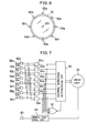
- Fig. 6 shows a second embodiment of the present invention in which four pairs of light-receiving means, i.e. eight optical fibers 50a to 50h are arranged along the periphery of the end plane of incidence 24. Respective optical fibers 50a to 50h are respectively connected to corresponding light-receiving elements 52a to 52h in the same manner as shown in Fig. 2, where output signals from the light-receiving elements 52a to 52h are fed to a signal processing circuit of Fig. 7.
- the signal processing circuit illustrated in Fig. 7 includes AND gates 54a to 54h each having an inverted input terminal, a control direction determining circuit 56 and and a NOR 57 gate both receiving output signals from the AND gates 54a to 54h.
- the control direction determining circuit 56 is used to determine the direction of the movement of the equatorial 16 performed by a drive unit 60 on the basis of the output signals from the AND gates 54a to 54h. More specifically, control direction of the equatorial mounting 16 is determined by which optical fiber or fibers is/are receiving incident sun light. In the case two or more optical fibers detect incidence of sunlight the control direction is selected to be a middle of end planes of incidence of such plural optical fibers. In order determine the control direction, a memory map may be used.
- the NOR gate 57 is arranged to produce an output signal for interrupting and restarting normal tracking operation in the same manner as in the first embodiment of Fig. 5.
- additional light-receiving means 50i has been provided within the end plane of incidence 24.
- the additional light-receiving means 50i is an optical fiber like other light-receiving means 50a to 50h, and is connected to a corresponding light-receiving element 52i.
- An output signal from the light-receiving element 52i is inputted to a speed control circuit 58.
- the speed control circuit 58 is arranged to produce a speed control signal which causes the drive unit 60 to operate at a high speed when the light-receiving element 52i does not detect sun light, and to operate at a low speed when sun light is detected. More specifically, as shown in Fig. 8 when an irradiated portion 36 as a result of sun light condensation deviates to one side so that the center of the end plane of incidence 24 is not irradiated, the equatorial mounting 16 is moved at a high speed. Then as shown in Fig. 9, when the irradiated portion 36 is moved to include the center portion, then the moving speed of the equatorial mounting 16 is reduced. With such speed control, position control of the equatorial mounting 16 is effected within a short period of time and also the occurrence of hunting is effectively prevented.
- Fig. 10 shows a third embodiment which includes a circuit arrangement for detecting abnormal condition of the optical system of the sunlight condensing apparatus.
- This embodiment also comprises an optical fiber 50i for detecting irradiating condition at the center of the end plane 24 in the same manner as in the second embodiment of Figs. 6 and 7.
- another optical fiber 62 is provided at place where sunlight is applied without passing through the filter 12 and the Fresnel lens 14 which constitute the optical system of the sunlight condensing apparatus, and a light-receiving element 64 responsive to the optical fiber 62 is provided.
- An abnormal condition of the optical system is determined on the basis of output signals from the light-receiving elements 52i and 64 to output an alarm such as a buzzer signal.
- an alarm such as a buzzer signal.
- the output signal from the light-receiving element 52 is applied to an input of a monostable multivibrator (MSMV) 68 and to an inverted input of an AND gate 66.
- the monostable multivibrator 66 is arranged to cause its output logic level to be zero for a predetermined period of time when triggered by a rising edge (trailing edge) of the output signal from the light-receiving element 52i.
- This predetermined period of time is set to a period of time (for instance 10 seconds) which is longer than a maximum period of time normally required until the irradiated portion 36 which is deviated from the end plane 24 is moved to be completely within the end plane 24 through position control of the equatorial mounting 16.
- the output signal from the monostable multivibrator 68 is applied to an input of the AND gate 66.
- An output signal from the light-receiving element 64 is also applied to the AND gate 66.
- the output signal from the AND gate 66 is fed to an alarm 70. Any alarm device which emits sound like a buzzer or a bell or which flashes a lamp or the like may be used as this alarm 70.
- the combination of the optical fiber 62 which directly receives sun light and light-receiving element 64 is referred to as external light-receiving means, and the combination of the optical fiber 50i provided within the end plane of incidence 24 and light-receiving element 52i is referred to as internal light-receiving means.
- the relationship between sun light detecting condition by the external light-receiving means and by the internal light-receiving means, the output signal from the monostable multivibrator 68, and the output signal from the AND gate 66 is shown in Fig. 11. Let us assume that sun light incidence on the sun light condensing apparatus is interrupted at time t1 for a short period of time (till t2) by clouds, birds or the like.
- Both the external light-receiving means and the internal light-receiving means detect this interruption and thus the monostable multivibrator 68 produces a signal of logic "0" till time t3. Therefore, the output signal of the AND gate 66 is kept logic "0" even after time t3 and no alarm is issued.
- the internal light-receiving means does not detect sun light incidence at time t4. While the monostable multivibrator 68 produces a signal of logic "0” till time t5 as being triggered, the output of the AND gate 66 is continuously kept logic "0" even thereafter, and therefore no alarm is issued.
- circuit arrangement of Fig. 10 By using the circuit arrangement of Fig. 10, an alarm is issued only when abnormal condition occurs in the optical system through detection of the same. Therefore, this embodiment is advantageous in connection with maintenance of the sun light condensing apparatus. Furthermore, the circuit arrangement of Fig. 10 may be provided with the circuit arrangement for speed control shown in Fig. 7, and in such a case, the optical fiber 50i and the light-receiving element 52i may respectively be used in common to both circuit arrangements.
- the apparatus for following sunlight according to the present invention described in detail in the above have the following advantages.
- First of all since plural pairs of light-receiving means for detecting tracking error, i.e. axis deviation, are arranged along the periphery of the circular portion where sun light is to be condensed, high accuracy in mounting position and direction of each light-receiving means is not required to be as high as conventional systems. Furthermore, since sunlight is detected after being condensed by a Fresnel lens of sunlight condensing apparatus, there is no undesirable influence by diffused light as in the conventional apparatus.
- the apparatus in addition to the above features since the degree of axis deviation is detected to control the moving speed of the equatorial driven by the drive unit, axis deviation can be corrected within a short period of time, while hunting is effectively prevented. Furthermore, in the third embodiment of the present invention, in addition to the features of the first embodiment since abnormal condition of the optical system is detected to issue an alarm, the apparatus is advantageous in view of maintenance. Especially, the third embodiment is advantageous because light-receiving means provided within the end plane of sunlight incidence which is used in the second embodiment can be used in common as sun light detecting means for detecting such abnormal condition.
Landscapes
- Physics & Mathematics (AREA)
- Radar, Positioning & Navigation (AREA)
- Electromagnetism (AREA)
- Engineering & Computer Science (AREA)
- General Physics & Mathematics (AREA)
- Remote Sensing (AREA)
- Sustainable Development (AREA)
- Life Sciences & Earth Sciences (AREA)
- Non-Portable Lighting Devices Or Systems Thereof (AREA)
- Photometry And Measurement Of Optical Pulse Characteristics (AREA)
- Light Guides In General And Applications Therefor (AREA)
- Mounting And Adjusting Of Optical Elements (AREA)
- Control Of Position Or Direction (AREA)
- Photovoltaic Devices (AREA)
Abstract
Description
- This invention relates generally to apparatus for following sunlight, and particularly to apparatus which is used with sunlight collecting apparatus arranged to condense sunlight and to send it to a place where sunlight is needed via an optical fiber cable.
- Various apparatus for following sunlight are known. For example, one apparatus is arranged to sense sunlight, one is arranged to perform numerical control through computation of the path of the sun, one is arranged to move a focal point portion (e.g. a parabolic mirror), and one is arranged to utilize a fixed device which is inclined in a manner of south side down and north side up. Another type of sunlight condensing apparatus condenses sunlight using a Fresnel lens and automatically changes its angle to face the sun, and sends condensed sunlight via an optical fiber cable to a place where the light is needed. An example of this apparatus is the sunlight automatic condensing and transmission apparatus known as "HIMAWARI" produced by La Foret Engineering Co. Ltd. When using a Fresnel lens for condensing sunlight, a slight difference in angle of several degrees or less between the light and the Fresnel lens results in serious difficulty in condensing the sunlight. Therefore, high precision apparatus for following the sunlight is required. In addition, axis deviation or misalignment may occur due to electrical or mechanical error even though an equatorial mounting is controlled in accordance with orbital computation. For such reason, a method which combines sunlight sensing and numerical control through orbital computation is generally adopted.
- An example of known sunlight sensing apparatus is disclosed in Japanese Patent provisional publication 59-15809. According to the technique disclosed in this publication a casing provided separately from a Fresnel lens is accurately directed to the sun, and a plurality of photo-sensors are provided within the casing to detect the difference in intensity of light thereby correcting axis deviation.
- The abovementioned conventional apparatus has the following problems since the sunlight sensor is located remote from the light-condensing portion where a Fresnel lens and the end of the optical fiber cable are located:
- (1) A high precision in mounting the apparatus is required for determining the position and direction of the sunlight sensor in accordance with the position and direction of a Fresnel lens.
- (2) Diffused light which cannot be used by the sunlight condensing apparatus undesirably influences the sunlight sensor.
- The present invention has been developed in order to reduce or remove the abovedescribed drawbacks inherent in the conventional apparatus for following sunlight and which is capable of providing a higher accuracy in tracking at a lower cost.
- According to the present invention there is provided apparatus for following sunlight for use with sunlight condensing apparatus with a lens, said apparatus for following sunlight being arranged to perform normal tracking in accordance with data including longitude and latitude, the geographical location of the apparatu, the number of days after vernal equinox and time, characterised by at least two pairs of light-detecting means, the number of each pair provided on opposing edges of a region onto which said sunlight is to be condensed, a signal processing circuit responsive to output signals from said light-detecting means for producing a control signal in response to differences between the members of a pair of incident light thereon caused by misalignment of the apparatus and means for interrupting said normal tracking in the presence of said control signal and for moving said sunlight condensing apparatus in a direction to realign the apparatus.
- Thus with the present invention at least two pairs of light-receiving means provided at opposite positions along the periphery of an end plane of incidence of an optical fiber, i.e. a circular portion where sunlight is to be condensed by a lens, are provided to produce a control signal when there is a difference in incident light intensity on the members of a pair, and in response to this the tracking direction is corrected.
- Preferably, when only one of the two opposite light-detecting means senses sunlight, a control signal is produced to interrupt normal tracking operation and to move the light-condensing apparatus in a given direction. Thus, in the case a portion where light is condensed by a lens protrudes beyond an end plane of incidence of an optical fiber cable, light-detecting means located at a place of such protrusion detects this to perform position control in a direction of correcting the protrusion. Furthermore, in an abnormal case in which the light-condensing portion protrudes into two opposite portions of the end plane of incidence of the fiber cable, it cannot be determined in which direction position correction is to be made, and therefore no position correction is made.
- Preferably another light-receiving means is also provided within the circular portion where sunlight is to be condensed, and it is arranged to control the moving speed of the equatorial depending on whether sunlight is detected by this light-receiving means.
- Thus, as light-detecting means is also provided within the end plane of an optical fiber cable to detect sunlight, thereby to control the moving speed of the equatorial mounting, the moving speed of the equatorial mounting may be selected for correcting the deviation of sunlight condensing area from the end plane depending on the degree of such deviation.
- As a further preferred feature, means for receiving sunlight not through an optical system of condensing apparatus are provided in addition to the structure of the first embodiment to detect abnormal condition of the optical system by comparison with means for receiving sunlight through the optical system which may be an additional detector on one or more of the detectors used for maintaining the alignment of the system. Thus, sunlight not passed through an optical system including e.g. a filter and a lens, of light condensing apparatus and sunlight passed through the optical system are respectively detected, and therefore an abnormal condition of the optical system may be detected to produce an alarm signal. Furthermore, by utilizing light-detecting means already provided in the optical system this feature may be easily combined with other features of the invention.
- The invention will be further described by way of non-limitative example with reference to the accompanying drawing in which:-
- Fig. 1 is a schematic structural view of apparatus for collecting sunlight utilizing sunlight condensing apparatus having a first embodiment of the apparatus for following sunlight according to the present invention;
- Fig. 2 is a diagram showing the arrangement of a plurality of optical fibers for detecting sunlight which are arranged along the periphery of a light condensing portion within the apparatus of Fig. 1, and light-receiving elements responsive to optical signals sent via the optical fibers;
- Figs. 3 and 4 are diagrams showing the positional relationship between end plane of incidence of Fig. 2 and condensed sunlight;
- Fig. 5 is a diagram showing a control signal producing circuit to which output signals from light-receiving elements of Fig. 2 are inputted, and a drive unit which performs position control of the equatorial shown in Fig. 1;
- Fig. 6 is a diagram showing an end plane of incidence of the optical fiber in a second embodiment of the apparatus for following sunlight according to the present invention;
- Fig. 7 is a diagram showing light-receiving elements responsive to optical signals from respective optical fibers shown in Fig. 6, signal processing circuit and speed control circuit both connected thereto, and drive unit which performs position control of the equatorial;
- Figs. 8 and 9 are diagrams showing positional relationship between end plane of incidence and sunlight in the second embodiment;
- Fig. 10 is a diagram showing a third embodiment of the apparatus for following sunlight according to the present invention; and
- Fig. 11 is a timing chart showing the operation of the circuit arrangement of Fig. 10.
- Reference is now made to Fig. 1 which shows apparatus for collecting sunlight in which a first embodiment of the apparatus for following sunlight according to the present invention is incorporated. More specifically, the apparatus for collecting sunlight comprises
sunlight following apparatus 18, andequatorial mounting 16, light-condensingportion casing 10, and light-takingoptical fiber cable 20 all mounted on abase 22. Sunlight is condensed by a Fresnellens 14 to be incident on anend plane 24 of theoptical fiber cable 20 with infrared rays being eliminated by afilter 12 attached to a front portion of the light-condensing portion casing 10. In order to track sunlight, the equatorial mounting 16 andsunlight following apparatus 18 according to the present invention are provided. - The Fresnel
lens 14 is made of transparent PMMA (polymethylmethacrylate), and has radius of 150 mm and focal length of 412 mm. Theoptical fiber cable 20 may use a plastic optical fiber made by Mitsubishi Rayon Co., Ltd. named "Eska" (trademark). The angle of view (40°) of the Fresnellens 14 is made smaller than the opening angle (60°) of "Eska". The radius of the sun is 6.95 x 10⁵ km, and the distance to the earth is 1.5 x 10⁸ km. Due to its elliptical orbit the visual angle varies slightly and is approximately 32 minutes. Therefore, when the focal point of the Fresnellens 14 is placed on the end plane ofincidence 24 of theoptical fiber cable 20, the diameter of a resulted image of the sun is 3.8 mm. Actually, acondensing area 36 is slightly larger than the above due to an unsharpened image caused by aberration in the Fresnellens 14. Theoptical fiber cable 20 has a diameter of 7.5 mm and comprises a tube tightly filled with 39 Eskas each having a diameter of 1 mm. - The
sunlight following apparatus 18 performs position control normally to follow moving incident sunlight in accordance with the following equations: - For the direction of declination:
δ = 23.5° X sin(2πT/365) + 54.5 (1)
wherein δ is declination of the sun; and
T is the number of days counted from vernal equinox. - Therefore, the movement of the sun from winter solstice to summer solstice in terms of angle is 47°.
- For the direction of right ascension:
H = 15° X (t - 12 + p / 15 + e) (2)
wherein H is right ascension of the sun;
t is time;
p is (longitude of the mounting point - longitude of standard time (135° E); and
e is equation of time (+16.4 14.3m) - Thus, the sun moves 360° a day, i.e. 15° an hour, and the equatorial 16 is moved in units of 0.76 second.
- The accuracy of polar axis setting of the
equatorial mounting 16 is within 3 minutes, the light-guidance error of the sunlight following apparatus 18 during operation is approximately 20 minutes, and since the frequency of a crystal oscillator used for generating a basic clock of a timer of the sunlight following apparatus 18 is calibrated to 5 digits, the overall accuracy is within 26 seconds per month (i.e. 6.5 minutes in terms of right ascension per month). - Fig. 2 shows an arrangement of light-receiving means used for apparatus for following sunlight according to the present invention. Around the end plane of
incidence 24 of theoptical fiber cable 20 are arranged the ends of fouroptical fibers optical fibers 30a to 30d are connected to light-receivingelements 32a, 32bj, 32c and 32d, such as photodiodes, to detect deviation in light condensation at the periphery of theend plane 24 of theoptical fiber cable 20. Amember 34 is used to mount the light-receivingelements 32a to 32d, and is attached at an appropriate position within theequatorial mounting 16 or thesunlight following apparatus 18 of Fig. 1. - Figs. 3 and 4 are top plan views of the
end plane 24 of theoptical fiber cable 20 of Fig. 2. Theend plane 24 of theoptical fiber cable 20 is circular, and during normal tracking operation sunlight is condensed to be applied to the entire area of thecircular end plane 24 by way of the Fresnel lengs 14 as shown by a hatched area in Fig. 3. At this time, none of theoptical fibers 30a to 30d receives sunlight. In Fig. 3, the direction from 30b to 30d is the direction of right ascension and the direction from 30a to 30d is the direction of declination. On the other hand, when axis deviation occurs due to some reason, such as an electrical or mechanical error during normal tracking operation based on the formulas (1) and (2), correction is then required. - Fig. 4 shows a state where condensed sunlight is applied beyond the circular portion of the
end plane 24 to protrude to a side of theoptical fiber 30d. In this case, only the light-receivingelement 30d detects sun light to produce an output signal. - Fig. 5 shows a diagram of a circuit which generates a control signal by processing output signals from the light-receiving
elements 32a to 32d. Thereferences 38a to 38d are lead wires of the light-receivingelements 32a to 32d. Thereferences 40a to 40d are AND gates whose one input terminal is an inverted input, and each of them is responsive to electrical signals from each pair of light-receivingelements 32a to 32d responsive to optical signals from each pair of diametrically oppositeoptical fibers 30a to 30d. Thereference 42 is a NOR gate which is responsive to an output signal from output signals from the ANDgates 40a to 40d. Under the light condensing state of Fig. 4, only the light-receivingelement 32d responsive to theoptical fiber 30d senses the incident light, whereas others do not sense the incident light, and thus only the ANDgate 40d produces logic "1". In response to the signal of logic "1" the NORgate 42 outputs logic "0". Outputs of the respective ANDgates 40a to 40d and the NORgate 42 are inputted to a driveunit control circuit 44. An output signal from the driveunit control circuit 44 is connected to adrive unit 46 which performs direction control of the equatorial 16 in accordance with output signals from the driveunit control circuit 44. When logic "1" output from the NORgate 42 turns to logic "0", normal tracking operation performed till this time in accordance with the formulas (1) and (2) is interrupted, and is switched to position control on the basis of the output signals from the ANDgates 40a to 40d. More specifically, the driveunit control circuit 44 includes a switching circuit (not shown) responsive to the output signal from the NORgate 42, and in the presence of logic "0" signal from the NORgate 42, the driveunit control circuit 44 is becomes responsive to the output signals from the ANDgates 40a to 40d. - The relationship between the state of sun light incident on respective
optical fibers 30a to 30d and the control direction of the equatorial mounting 16 is shown in the following table. In this table, the reference ON indicates sun light incidence and the reference OFF indicates the absence of sun light incidence. Arrows in the column of control direction of the equatorial mounting 16 indicates various directions, i.e. right, left, up and down in Fig. 3. When the incident light is not applied to any of theoptical fibers 30a to 30d, i.e. in OFF state, the NORgate 42 produces logic "1" to restore normal tracking operation.
- Although four
optical fibers 30a to 30d are used in the present embodiment such that two pairs of light-receiving means are arranged along the periphery of the end plane ofincidence 24 with an interval of 90°, the number of pairs of light-receiving means may be any number as long as it is 2 or more. - Fig. 6 shows a second embodiment of the present invention in which four pairs of light-receiving means, i.e. eight
optical fibers 50a to 50h are arranged along the periphery of the end plane ofincidence 24. Respectiveoptical fibers 50a to 50h are respectively connected to corresponding light-receivingelements 52a to 52h in the same manner as shown in Fig. 2, where output signals from the light-receivingelements 52a to 52h are fed to a signal processing circuit of Fig. 7. - The signal processing circuit illustrated in Fig. 7 includes AND
gates 54a to 54h each having an inverted input terminal, a controldirection determining circuit 56 and and a NOR 57 gate both receiving output signals from the ANDgates 54a to 54h. The controldirection determining circuit 56 is used to determine the direction of the movement of the equatorial 16 performed by adrive unit 60 on the basis of the output signals from the ANDgates 54a to 54h. More specifically, control direction of the equatorial mounting 16 is determined by which optical fiber or fibers is/are receiving incident sun light. In the case two or more optical fibers detect incidence of sunlight the control direction is selected to be a middle of end planes of incidence of such plural optical fibers. In order determine the control direction, a memory map may be used. - The NOR
gate 57 is arranged to produce an output signal for interrupting and restarting normal tracking operation in the same manner as in the first embodiment of Fig. 5. In the second embodiment of Figs. 6 and 7, not only the number of pairs of light-receiving means has been increased compared to the first embodiment of Figs. 2 to 5, but also additional light-receivingmeans 50i has been provided within the end plane ofincidence 24. The additional light-receivingmeans 50i is an optical fiber like other light-receiving means 50a to 50h, and is connected to a corresponding light-receivingelement 52i. An output signal from the light-receivingelement 52i is inputted to aspeed control circuit 58. - The
speed control circuit 58 is arranged to produce a speed control signal which causes thedrive unit 60 to operate at a high speed when the light-receivingelement 52i does not detect sun light, and to operate at a low speed when sun light is detected. More specifically, as shown in Fig. 8 when anirradiated portion 36 as a result of sun light condensation deviates to one side so that the center of the end plane ofincidence 24 is not irradiated, the equatorial mounting 16 is moved at a high speed. Then as shown in Fig. 9, when the irradiatedportion 36 is moved to include the center portion, then the moving speed of the equatorial mounting 16 is reduced. With such speed control, position control of the equatorial mounting 16 is effected within a short period of time and also the occurrence of hunting is effectively prevented. - Fig. 10 shows a third embodiment which includes a circuit arrangement for detecting abnormal condition of the optical system of the sunlight condensing apparatus. This embodiment also comprises an
optical fiber 50i for detecting irradiating condition at the center of theend plane 24 in the same manner as in the second embodiment of Figs. 6 and 7. In addition, anotheroptical fiber 62 is provided at place where sunlight is applied without passing through thefilter 12 and theFresnel lens 14 which constitute the optical system of the sunlight condensing apparatus, and a light-receivingelement 64 responsive to theoptical fiber 62 is provided. An abnormal condition of the optical system is determined on the basis of output signals from the light-receivingelements element 52 is applied to an input of a monostable multivibrator (MSMV) 68 and to an inverted input of an ANDgate 66. Themonostable multivibrator 66 is arranged to cause its output logic level to be zero for a predetermined period of time when triggered by a rising edge (trailing edge) of the output signal from the light-receivingelement 52i. This predetermined period of time is set to a period of time (forinstance 10 seconds) which is longer than a maximum period of time normally required until the irradiatedportion 36 which is deviated from theend plane 24 is moved to be completely within theend plane 24 through position control of the equatorial mounting 16. The output signal from themonostable multivibrator 68 is applied to an input of the ANDgate 66. An output signal from the light-receivingelement 64 is also applied to the ANDgate 66. The output signal from the ANDgate 66 is fed to analarm 70. Any alarm device which emits sound like a buzzer or a bell or which flashes a lamp or the like may be used as thisalarm 70. - The combination of the
optical fiber 62 which directly receives sun light and light-receivingelement 64 is referred to as external light-receiving means, and the combination of theoptical fiber 50i provided within the end plane ofincidence 24 and light-receivingelement 52i is referred to as internal light-receiving means. The relationship between sun light detecting condition by the external light-receiving means and by the internal light-receiving means, the output signal from themonostable multivibrator 68, and the output signal from the ANDgate 66 is shown in Fig. 11. Let us assume that sun light incidence on the sun light condensing apparatus is interrupted at time t1 for a short period of time (till t2) by clouds, birds or the like. Both the external light-receiving means and the internal light-receiving means detect this interruption and thus themonostable multivibrator 68 produces a signal of logic "0" till time t3. Therefore, the output signal of the ANDgate 66 is kept logic "0" even after time t3 and no alarm is issued. Let us suppose that an error occurs in the normal tracking operation of the equatorial 16 and as a result, the internal light-receiving means does not detect sun light incidence at time t4. While themonostable multivibrator 68 produces a signal of logic "0" till time t5 as being triggered, the output of the ANDgate 66 is continuously kept logic "0" even thereafter, and therefore no alarm is issued. - Suppose incidence of sun light is interrupted for a long period of time from time t6 to time t8 by clouds or the like. In this case, although the output of the
monostable multivibrator 68 turns to logic "1" at time t7, the output of the ANDgate 66 is maintained logic "0" because the external light-receiving means does not detect sun light even thereafter. As a result, no alarm is issued. Let us suppose that serious abnormality, such as breakage, warping or the like, has occurred in thefilter 12, theFresnel lens 14 or the like of Fig. 1. Since sun light condensation and application of the same to the end plane ofincidence 24 is interrupted for a long period of time, the output of the ANDgate 66 turns to logic "1" at time t10 and thus thealarm 70 is driven. - By using the circuit arrangement of Fig. 10, an alarm is issued only when abnormal condition occurs in the optical system through detection of the same. Therefore, this embodiment is advantageous in connection with maintenance of the sun light condensing apparatus. Furthermore, the circuit arrangement of Fig. 10 may be provided with the circuit arrangement for speed control shown in Fig. 7, and in such a case, the
optical fiber 50i and the light-receivingelement 52i may respectively be used in common to both circuit arrangements. - The apparatus for following sunlight according to the present invention described in detail in the above have the following advantages. First of all, since plural pairs of light-receiving means for detecting tracking error, i.e. axis deviation, are arranged along the periphery of the circular portion where sun light is to be condensed, high accuracy in mounting position and direction of each light-receiving means is not required to be as high as conventional systems. Furthermore, since sunlight is detected after being condensed by a Fresnel lens of sunlight condensing apparatus, there is no undesirable influence by diffused light as in the conventional apparatus. Furthermore, in the second embodiment of the present invention, in addition to the above features since the degree of axis deviation is detected to control the moving speed of the equatorial driven by the drive unit, axis deviation can be corrected within a short period of time, while hunting is effectively prevented. Furthermore, in the third embodiment of the present invention, in addition to the features of the first embodiment since abnormal condition of the optical system is detected to issue an alarm, the apparatus is advantageous in view of maintenance. Especially, the third embodiment is advantageous because light-receiving means provided within the end plane of sunlight incidence which is used in the second embodiment can be used in common as sun light detecting means for detecting such abnormal condition.
- The above-described embodiments are just examples of the present invention, and therefore, it will be apparent for those skilled in the art that many modifications and variations may be made without departing from the scope of the present invention.
Claims (11)
Applications Claiming Priority (2)
| Application Number | Priority Date | Filing Date | Title |
|---|---|---|---|
| JP146025/87 | 1987-06-11 | ||
| JP62146025A JPS63310010A (en) | 1987-06-11 | 1987-06-11 | solar tracking device |
Publications (3)
| Publication Number | Publication Date |
|---|---|
| EP0295152A2 true EP0295152A2 (en) | 1988-12-14 |
| EP0295152A3 EP0295152A3 (en) | 1989-09-06 |
| EP0295152B1 EP0295152B1 (en) | 1993-09-15 |
Family
ID=15398399
Family Applications (1)
| Application Number | Title | Priority Date | Filing Date |
|---|---|---|---|
| EP88305400A Expired - Lifetime EP0295152B1 (en) | 1987-06-11 | 1988-06-13 | Apparatus for following sun light |
Country Status (6)
| Country | Link |
|---|---|
| US (1) | US4942292A (en) |
| EP (1) | EP0295152B1 (en) |
| JP (1) | JPS63310010A (en) |
| KR (1) | KR970004814B1 (en) |
| AU (1) | AU586142B2 (en) |
| DE (1) | DE3884063T2 (en) |
Cited By (5)
| Publication number | Priority date | Publication date | Assignee | Title |
|---|---|---|---|---|
| DE4125783A1 (en) * | 1991-08-03 | 1993-02-04 | Askon Aldenhoff & Schnell Kons | Table arrangement fitting onto vehicle seat - uses fold away construction with horizontally extendible tops |
| WO2008100200A1 (en) * | 2007-02-12 | 2008-08-21 | Parans Solar Lighting Ab | Light collecting device |
| EP2348261A4 (en) * | 2008-11-17 | 2012-08-01 | Tm Tech Co Ltd | Optical sensor holder for tracking sunlight |
| ITFI20120248A1 (en) * | 2012-11-16 | 2014-05-17 | Maurizio Carlini | POINTING DEVICE PARTICULARLY FOR RENEWABLE SOURCES |
| EP3222930A1 (en) * | 2016-03-22 | 2017-09-27 | Jon Ramstedt | Solar lighting system and method for controlling a solar lighting system |
Families Citing this family (16)
| Publication number | Priority date | Publication date | Assignee | Title |
|---|---|---|---|---|
| JPH01135607U (en) * | 1988-03-10 | 1989-09-18 | ||
| JPH0377903A (en) * | 1989-08-21 | 1991-04-03 | Fujio Aramaki | Method and device for condensing sunlight |
| JPH0792699B2 (en) * | 1990-08-09 | 1995-10-09 | 藤夫 荒牧 | Solar concentrator |
| US5079414A (en) * | 1990-10-09 | 1992-01-07 | Gte Government Systems Corporation | Tracking telescope using an atomic resonance filter |
| WO1993010393A1 (en) * | 1991-11-13 | 1993-05-27 | Graham James Wood | A light collection system for a skylight |
| KR100370371B1 (en) * | 2000-03-22 | 2003-01-30 | 유춘영 | Method for controlling a reproduction of portable cd player |
| JP2003215348A (en) * | 2002-01-22 | 2003-07-30 | Fuji Photo Film Co Ltd | Light guide film |
| KR100673556B1 (en) | 2006-02-01 | 2007-01-25 | (주) 아주광학 | Natural light device using aspherical lens |
| US7645973B2 (en) * | 2007-10-15 | 2010-01-12 | Chien-Feng Lin | Sun-tracking power generating apparatus |
| WO2010051595A1 (en) * | 2008-11-07 | 2010-05-14 | Soliton Network Consulting Pty Ltd | A light distribution system |
| US20100288266A1 (en) * | 2009-05-12 | 2010-11-18 | Arthur Drevnig | Solar Heater |
| KR101313723B1 (en) | 2010-11-27 | 2013-10-01 | 요크공조(주) | structure for condensing sunlight and Apparatus for transmitting sunlight |
| US8395279B2 (en) * | 2011-06-15 | 2013-03-12 | General Electric Company | Shadow detection apparatus using fiber optics for solar-based power generation plants |
| DE102011114898A1 (en) | 2011-10-05 | 2013-04-11 | Rainer Schmidt | Light guiding arrangement for use in e.g. photovoltaic system, has optical element whose side is connected with connection for fluid or with connection for medium, where remaining sides of element are designed as limiting surfaces |
| DE102012011058A1 (en) | 2012-06-04 | 2013-12-05 | Rainer Schmidt | Controllable light control and light line has optical transparent portion and release liner whose light entrance surface is set back by total reflectance, such that optical transparent portion is impinged on conversion element |
| US20150136944A1 (en) * | 2013-11-21 | 2015-05-21 | Avraham Segev | Sunlight tracking sensor and system |
Family Cites Families (9)
| Publication number | Priority date | Publication date | Assignee | Title |
|---|---|---|---|---|
| US4107521A (en) * | 1976-10-14 | 1978-08-15 | Gordon Robert Winders | Solar sensor and tracker apparatus |
| DE2711570A1 (en) * | 1977-03-17 | 1978-09-21 | Peter Schlueter | Solar heat collector control device - adjusts orientation of reflectors according to position of sun to maximise collection efficiency |
| US4290411A (en) * | 1978-06-05 | 1981-09-22 | Russell George F | Solar energy collector sun-tracking apparatus and method |
| US4447718A (en) * | 1980-07-07 | 1984-05-08 | Kei Mori | Apparatus for collecting and concentrating solar light energy |
| JPS585704A (en) * | 1981-07-01 | 1983-01-13 | Takashi Mori | Automatic tracking device for solar light |
| FR2531232A1 (en) * | 1982-07-30 | 1984-02-03 | Trt Telecom Radio Electr | OPTICAL SELF-DIAGRAM SYSTEM WITH IMAGING |
| JPS61137103A (en) * | 1984-12-07 | 1986-06-24 | Mitsubishi Rayon Co Ltd | Solar light condensing and transmitting device |
| US4740682A (en) * | 1986-07-23 | 1988-04-26 | Michael Frankel | Optical tracking, focusing, and information receiving device including a pyramidal light splitter |
| JPS6376203A (en) * | 1986-09-18 | 1988-04-06 | 森 敬 | solar collector |
-
1987
- 1987-06-11 JP JP62146025A patent/JPS63310010A/en active Pending
-
1988
- 1988-06-09 US US07/206,831 patent/US4942292A/en not_active Expired - Fee Related
- 1988-06-10 AU AU17625/88A patent/AU586142B2/en not_active Ceased
- 1988-06-11 KR KR1019880007028A patent/KR970004814B1/en not_active Expired - Fee Related
- 1988-06-13 DE DE88305400T patent/DE3884063T2/en not_active Expired - Fee Related
- 1988-06-13 EP EP88305400A patent/EP0295152B1/en not_active Expired - Lifetime
Cited By (5)
| Publication number | Priority date | Publication date | Assignee | Title |
|---|---|---|---|---|
| DE4125783A1 (en) * | 1991-08-03 | 1993-02-04 | Askon Aldenhoff & Schnell Kons | Table arrangement fitting onto vehicle seat - uses fold away construction with horizontally extendible tops |
| WO2008100200A1 (en) * | 2007-02-12 | 2008-08-21 | Parans Solar Lighting Ab | Light collecting device |
| EP2348261A4 (en) * | 2008-11-17 | 2012-08-01 | Tm Tech Co Ltd | Optical sensor holder for tracking sunlight |
| ITFI20120248A1 (en) * | 2012-11-16 | 2014-05-17 | Maurizio Carlini | POINTING DEVICE PARTICULARLY FOR RENEWABLE SOURCES |
| EP3222930A1 (en) * | 2016-03-22 | 2017-09-27 | Jon Ramstedt | Solar lighting system and method for controlling a solar lighting system |
Also Published As
| Publication number | Publication date |
|---|---|
| AU1762588A (en) | 1988-12-15 |
| KR970004814B1 (en) | 1997-04-04 |
| DE3884063T2 (en) | 1994-01-13 |
| JPS63310010A (en) | 1988-12-19 |
| US4942292A (en) | 1990-07-17 |
| EP0295152A3 (en) | 1989-09-06 |
| EP0295152B1 (en) | 1993-09-15 |
| AU586142B2 (en) | 1989-06-29 |
| DE3884063D1 (en) | 1993-10-21 |
| KR890000905A (en) | 1989-03-17 |
Similar Documents
| Publication | Publication Date | Title |
|---|---|---|
| EP0295152B1 (en) | Apparatus for following sun light | |
| US4225781A (en) | Solar tracking apparatus | |
| US4082947A (en) | Solar collector and drive circuitry control means | |
| US2513367A (en) | Radiant energy tracking apparatus | |
| US4211922A (en) | Heliostat guidance | |
| US4349733A (en) | Sun tracker | |
| US4612488A (en) | Apparatus for controlling the directional orientation of a radiation receiver device to a light source | |
| US2981842A (en) | Automatic grid scanning tracker | |
| GB2030413A (en) | Photoelectric direction finding and luminous zone tracking | |
| ES8704271A1 (en) | Airborne optoelectrical target detection, localisation and omnidirectional tracking system. | |
| US3793518A (en) | Optical scanning system with a crossed scanning pattern | |
| JPS5299820A (en) | Focusing glass | |
| JPS6443845A (en) | Optical information recording and reproducing device | |
| KR940000835B1 (en) | Apparatus for following sun-light | |
| JPS5746334A (en) | Optical information reproducer | |
| JPH0157768B2 (en) | ||
| SU1576802A2 (en) | Orientation photosensor | |
| US4183641A (en) | Focus detecting device | |
| JPH0745053Y2 (en) | Solar tracking sensor | |
| SU1141274A1 (en) | Solar heat-collecting set | |
| SU1040290A1 (en) | Solar plant tracking system transducer | |
| JPS6488528A (en) | Remote control signal receiver for camera | |
| SU1325394A1 (en) | Magnetic variation station | |
| JPS60215499A (en) | Earth sensor | |
| JPS6329210A (en) | Sunshine tracking sensor device |
Legal Events
| Date | Code | Title | Description |
|---|---|---|---|
| PUAI | Public reference made under article 153(3) epc to a published international application that has entered the european phase |
Free format text: ORIGINAL CODE: 0009012 |
|
| AK | Designated contracting states |
Kind code of ref document: A2 Designated state(s): DE GB SE |
|
| PUAL | Search report despatched |
Free format text: ORIGINAL CODE: 0009013 |
|
| AK | Designated contracting states |
Kind code of ref document: A3 Designated state(s): DE GB SE |
|
| 17P | Request for examination filed |
Effective date: 19900131 |
|
| 17Q | First examination report despatched |
Effective date: 19920220 |
|
| GRAA | (expected) grant |
Free format text: ORIGINAL CODE: 0009210 |
|
| AK | Designated contracting states |
Kind code of ref document: B1 Designated state(s): DE GB SE |
|
| REF | Corresponds to: |
Ref document number: 3884063 Country of ref document: DE Date of ref document: 19931021 |
|
| PGFP | Annual fee paid to national office [announced via postgrant information from national office to epo] |
Ref country code: GB Payment date: 19940603 Year of fee payment: 7 |
|
| PGFP | Annual fee paid to national office [announced via postgrant information from national office to epo] |
Ref country code: DE Payment date: 19940608 Year of fee payment: 7 |
|
| PGFP | Annual fee paid to national office [announced via postgrant information from national office to epo] |
Ref country code: SE Payment date: 19940615 Year of fee payment: 7 |
|
| PLBE | No opposition filed within time limit |
Free format text: ORIGINAL CODE: 0009261 |
|
| STAA | Information on the status of an ep patent application or granted ep patent |
Free format text: STATUS: NO OPPOSITION FILED WITHIN TIME LIMIT |
|
| 26N | No opposition filed | ||
| EAL | Se: european patent in force in sweden |
Ref document number: 88305400.9 |
|
| PG25 | Lapsed in a contracting state [announced via postgrant information from national office to epo] |
Ref country code: GB Effective date: 19950613 |
|
| PG25 | Lapsed in a contracting state [announced via postgrant information from national office to epo] |
Ref country code: SE Effective date: 19950614 |
|
| GBPC | Gb: european patent ceased through non-payment of renewal fee |
Effective date: 19950613 |
|
| PG25 | Lapsed in a contracting state [announced via postgrant information from national office to epo] |
Ref country code: DE Effective date: 19960301 |
|
| EUG | Se: european patent has lapsed |
Ref document number: 88305400.9 |