EP0295155B1 - Modulschutzschalter, bestehend aus einem mit einem mehrpoligen Leistungsschutzschalterblock zusammenwirkenden Auslöseblock - Google Patents
Modulschutzschalter, bestehend aus einem mit einem mehrpoligen Leistungsschutzschalterblock zusammenwirkenden Auslöseblock Download PDFInfo
- Publication number
- EP0295155B1 EP0295155B1 EP19880401006 EP88401006A EP0295155B1 EP 0295155 B1 EP0295155 B1 EP 0295155B1 EP 19880401006 EP19880401006 EP 19880401006 EP 88401006 A EP88401006 A EP 88401006A EP 0295155 B1 EP0295155 B1 EP 0295155B1
- Authority
- EP
- European Patent Office
- Prior art keywords
- circuit breaker
- trip
- unit
- finger
- handle
- Prior art date
- Legal status (The legal status is an assumption and is not a legal conclusion. Google has not performed a legal analysis and makes no representation as to the accuracy of the status listed.)
- Expired - Lifetime
Links
- 230000005405 multipole Effects 0.000 title claims description 5
- 230000007246 mechanism Effects 0.000 claims description 37
- 230000008878 coupling Effects 0.000 claims description 12
- 238000010168 coupling process Methods 0.000 claims description 12
- 238000005859 coupling reaction Methods 0.000 claims description 12
- 230000005540 biological transmission Effects 0.000 claims description 10
- 230000009471 action Effects 0.000 claims description 6
- 230000002457 bidirectional effect Effects 0.000 claims description 4
- 230000001960 triggered effect Effects 0.000 description 7
- 230000035515 penetration Effects 0.000 description 2
- 230000009466 transformation Effects 0.000 description 2
- 230000007935 neutral effect Effects 0.000 description 1
Images


Classifications
-
- H—ELECTRICITY
- H01—ELECTRIC ELEMENTS
- H01H—ELECTRIC SWITCHES; RELAYS; SELECTORS; EMERGENCY PROTECTIVE DEVICES
- H01H83/00—Protective switches, e.g. circuit-breaking switches, or protective relays operated by abnormal electrical conditions otherwise than solely by excess current
- H01H83/20—Protective switches, e.g. circuit-breaking switches, or protective relays operated by abnormal electrical conditions otherwise than solely by excess current operated by excess current as well as by some other abnormal electrical condition
-
- H—ELECTRICITY
- H01—ELECTRIC ELEMENTS
- H01H—ELECTRIC SWITCHES; RELAYS; SELECTORS; EMERGENCY PROTECTIVE DEVICES
- H01H71/00—Details of the protective switches or relays covered by groups H01H73/00 - H01H83/00
- H01H71/10—Operating or release mechanisms
- H01H71/1009—Interconnected mechanisms
-
- H—ELECTRICITY
- H01—ELECTRIC ELEMENTS
- H01H—ELECTRIC SWITCHES; RELAYS; SELECTORS; EMERGENCY PROTECTIVE DEVICES
- H01H71/00—Details of the protective switches or relays covered by groups H01H73/00 - H01H83/00
- H01H71/02—Housings; Casings; Bases; Mountings
- H01H71/0264—Mountings or coverplates for complete assembled circuit breakers, e.g. snap mounting in panel
- H01H71/0271—Mounting several complete assembled circuit breakers together
- H01H2071/0278—Mounting several complete assembled circuit breakers together with at least one of juxtaposed casings dedicated to an auxiliary device, e.g. for undervoltage or shunt trip
Definitions
- the invention relates to a modular circuit breaker with auxiliary trip block, in particular differential or emission, capable of being coupled and coupled to a multipole circuit breaker block having a plurality of juxtaposed poles, each pole of said circuit breaker block comprising separable contacts and a first mechanism for actuating said contacts, controlled either manually by a first control handle with two stable opening and closing positions of the circuit breaker, or automatically by a main trip device cooperating with a trip bar in the event of overload or short-circuit circuit, said auxiliary trip unit containing an electromagnetic relay associated with a second control mechanism comprising a second reset lever for the trip unit and a first mechanical trip link capable of transmitting the trip order of the relay to the trip bar by engagement nt of a finger of the second mechanism in a hole in the insulating housing of the neighboring pole.
- the circuit breaker according to the invention is characterized in that a means of controlling the position of the first and second levers comprises a ramp arranged on the trip bar of the main trip device, and that the finger of the first mechanical link triggering the second mechanism is likely to come into engagement with said ramp to cause the forced tripping of the circuit breaker block in the event of a discrepancy between the levers, in particular during the association of a disarmed tripping block with a closed circuit breaker block, the movement of approaching the blocks being transformed into a pivoting movement of the trigger bar towards the triggered position.
- the second mechanism is equipped with a second mechanical link for resetting the trip unit comprising a transmission lug capable of driving the reset handle to the armed position during manual actuation of the handle of the first mechanism to the closed position. of the circuit breaker block.
- This second mechanical link can be unidirectional or bidirectional.
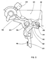
- an auxiliary trip unit 12 of the differential or emission type is attached and coupled to a two-pole circuit breaker unit 10 to constitute a differential circuit breaker or a remote-controlled circuit breaker.
- the circuit breaker block 10 is formed by the juxtaposition of two standard 14.16 poles each comprising a pair of connection terminals, a pair of separable 18.20 contacts (FIGS. 5 and 6) and a first actuation mechanism 22 controlled either manually by a control lever 24 with two stable positions for opening and closing the circuit breaker, or automatically by a main thermomagnetic trip device (not shown) actuating a common trip bar 26 in the event of an overload or short-circuit.
- the levers 24 of the two poles 14, 16 are mechanically linked together by a common bar 28.
- the mechanism 22 ( Figures 5 and 6) of each pole 14,16 is of the type described in European patent application No.
- 86 402 267 and comprises a trigger lever 30 pivotally mounted on an axis 32 carried by a plate 34 capable of rotating around a pivot 36 when the circuit breaker opens and closes.
- a transmission link 38 is interposed between the lever 24 and an attachment (not shown) of the plate 34, said attachment being unlocked by the trigger lever 30 during a fault detected by the magnetothermal trigger.
- This tripping order can be transmitted to the pole next to the block circuit breaker 10 by a finger 44 ( Figures 5 and 9), formed by an auxiliary needle connecting the extensions of the trigger levers 30 of the two poles.
- the finger 52 of the first mechanical connection 48 crosses the orifice 42 on the right of the pole 16, and cooperates either with a shoulder 62, or with a ramp 64 of the trigger lever 30 according to the armed or triggered state of the mechanisms 22,46 for controlling the blocks 10,12.
- the shoulder 62 extends parallel to the trigger finger 52 and is located between the ramp 64 and a housing 66 blind lever 30.
- the second link 50 could also be completely eliminated, and the separate resetting of the auxiliary trip unit 12 would in this case be done manually by actuation of the lever 54 before the circuit breaker unit 10 closes.
- FIG. 10 does not provide for forced triggering in the event of discordance of the levers 24.54, but an automatic return of the lever 54 of the trigger block 12 by means of a ratchet 70.
- the latter is advantageously integrated in the lug 56 of the handle 54.
Landscapes
- Breakers (AREA)
Claims (8)
- Leistungsschalter in Modulbauweise mit Hilfsauslöseblock (12), insbesondere einem Differenz- oder Arbeitsstromauslöser, zur Anreihung und Ankopplung an einen Mehrpol-Leistungsschalterblock (10) mit mehreren aneinandergereihten Schalterpolen, wobei jeder der Pole des genannten Leistungsschalterblocks (10) mit trennbaren Kontakten (18, 20) und einem ersten Antriebsmechanismus (22) ausgerüstet ist, mitdem die genannten Kontakte entweder manuell über einen ersten Betätigungshebel (24) mit zwei stabilen Schaltstellungen entsprechend der Einschalt- bzw. Ausschaltstellung des Leistungsschalters, oder im Überlast- bzw. Kurzschlußfall automatisch über die durch einen Hauptauslöser gesteuerte Auslösestange (26) betätigt werden, und der genannte Hilfsauslöseblock (12) mit einem elektromagnetischen Relais (45) bestückt ist, das auf einen zweiten Antriebsmechanismus (46) mit einem zugehörigen zweiten Betätigungshebel (54) zum Wiederspannen des Auslöseblocks (12) sowie einer ersten mechanischen Auslöseverbindung (48) wirkt, die dazu dient, durch Einpassen eines Zapfens (52) des zweiten Antriebsmechanismus (46) in eine entsprechende Öffnung (42) im lsolierstoffgehäuse (40) des angrenzenden Schalterpols (16) den Auslösebefehl des Relais (45) auf die Auslösestange (26) zu übertragen,
dadurch gekennzeichnet, daß im Ansteuermechanismus des ersten und des zweiten Betätigungshebels (24, 54) an der Auslösestange (26) des Hauptauslösers eine Schräge (64) ausgebildet ist und der Zapfen (52) der ersten mechanischen Auslöseverbindung (48) des zweiten Antriebsmechanismus (46) so auf die genannte Schräge (64) wirkt, daß eine Zwangsauslösung des Leistungsschalterblocks (10) bei unterschiedlicher Stellung der beiden Betätigungshebel (24, 54), insbesondere bei Ankopplung eines entspannten Auslöseblocks (12) an einen eingeschalteten Leistungsschalterblock (10) dadurch gewährleistet ist, daß die Ankopplung der beiden Blöcke (10, 12) ein Schwenken der Auslösestange (26) in die Ausgelöst-Stellung bewirkt. - Leistungsschalter in Modulbauweise nach Anspruch 1, dadurch gekennzeichnet, daß die durch Wirkung des Zapfens (52) auf die Schräge (64) hervorgerufene Zwangsauslösung des Leistungsschalterblocks (10) vor dem Ankoppeln der beiden Betätigungshebel (24, 54) des ersten und des zweiten Antriebsmechanismus (22, 46) erfolgt, da bei Berührung des Zapfens (52) und der Schräge (64) ein voreingestelltes Spiels J zwischen den genannten Betätigungshebeln verbleibt.
- Leistungsschalter in Modulbauweise nach Anspruch 2, dadurch gekennzeichnet, daß der zweite Antriebsmechanismus (46) eine zweite zum Wiederspannen des Auslöseblocks (12) dienende mechanische Verbindung (50) mit einen Mitnehmer (56) aufweist, der bei manuellem Umlegen des ersten Betätigungshebels (24) des ersten Antriebsmechanismus (22) in die Einschaltstellung des Leistungsschalterblocks (10) den zweiten Betätigungshebel (54) in die Gespannt-Stellung überführt.
- Leistungsschalter in Modulbauweise nach Anspruch 3, dadurch gekennzeichnet, daß die zweite mechanische Verbindung (50) zum Wiederspannen des Auslöseblocks (12) durch Anbringung des Mitnehmers (56) am zweiten Betätigungshebel (54) nur in einer Richtung wirkt, derart daß der Mitnehmer (56) nur während des Einschalthubs durch den ersten Betätigungshebel (24) des ersten Antriebsmechanismus (22) mitgeführt wird.
- Leistungsschalter in Modulbauweise nach Anspruch 3, dadurch gekennzeichnet, daß die zweite mechanische Verbindung (50) zum Wiederspannen des Auslöseblocks (12) durch direkte Verbindung des Mitnehmers (56) mit beiden Betätigungshebeln (24, 54) bidirektional wirkt, wobei der zweite Antriebsmechanismus (46) so ausgelegt ist, daß die Spannbewegung für das Relais (45) des Auslöseblocks (12) durch den Ausschalthub des ersten Antriebsmechanismus (22) bereitgestelltwird.
- Leistungsschalter in Modulbauweise nach einem der Ansprüche 1 bis 5, dadurch gekennzeichnet, daß der Auslöseblock (12) mit Ansatzstücken (60) zur Aufnahme durch die gegenüberliegenden Paßöffnungen (61) des Schalterpols (16) versehen ist, um die beiden aneinandergereihten Blöcke (10, 12) zu zentrieren, wobei die Ansatzstücke (60) und der Zapfen (52) der zweiten mechanischen Auslöseverbindung (48) aus der Innenseite des Auslöseblocks (12) herausragen und parallel zueinander angeordnet sind.
- Leistungsschalter in Modulbauweise nach Anspruch 6, dadurch gekennzeichnet, daß der Zapfen (52) der ersten mechanischen Auslöseverbindung (48) kürzer ist als die Ansatzstücke (60).
- Leistungsschalter in Modulbauweise nach einem der Ansprüche 1 bis 7, dadurch gekennzeichnet, daß sich die Schräge (64) zur Kraftübertragung auf die Auslösestange (26) direkt am Auslösehebel (30) des ersten Antriebsmechanismus (22) desjenigen Schalterpols (16) befindet, der an den Auslöseblock (12) grenzt.
Applications Claiming Priority (2)
| Application Number | Priority Date | Filing Date | Title |
|---|---|---|---|
| FR8706623A FR2615323B1 (fr) | 1987-05-11 | 1987-05-11 | Disjoncteur modulaire a bloc declencheur auxiliaire associe a un bloc disjoncteur multipolaire |
| FR8706623 | 1987-05-11 |
Publications (2)
| Publication Number | Publication Date |
|---|---|
| EP0295155A1 EP0295155A1 (de) | 1988-12-14 |
| EP0295155B1 true EP0295155B1 (de) | 1992-10-28 |
Family
ID=9350996
Family Applications (1)
| Application Number | Title | Priority Date | Filing Date |
|---|---|---|---|
| EP19880401006 Expired - Lifetime EP0295155B1 (de) | 1987-05-11 | 1988-04-25 | Modulschutzschalter, bestehend aus einem mit einem mehrpoligen Leistungsschutzschalterblock zusammenwirkenden Auslöseblock |
Country Status (4)
| Country | Link |
|---|---|
| EP (1) | EP0295155B1 (de) |
| DE (1) | DE3875528T2 (de) |
| ES (1) | ES2035934T3 (de) |
| FR (1) | FR2615323B1 (de) |
Cited By (71)
| Publication number | Priority date | Publication date | Assignee | Title |
|---|---|---|---|---|
| US6037555A (en) | 1999-01-05 | 2000-03-14 | General Electric Company | Rotary contact circuit breaker venting arrangement including current transformer |
| US6087913A (en) | 1998-11-20 | 2000-07-11 | General Electric Company | Circuit breaker mechanism for a rotary contact system |
| US6114641A (en) | 1998-05-29 | 2000-09-05 | General Electric Company | Rotary contact assembly for high ampere-rated circuit breakers |
| US6166344A (en) | 1999-03-23 | 2000-12-26 | General Electric Company | Circuit breaker handle block |
| US6172584B1 (en) | 1999-12-20 | 2001-01-09 | General Electric Company | Circuit breaker accessory reset system |
| US6175288B1 (en) | 1999-08-27 | 2001-01-16 | General Electric Company | Supplemental trip unit for rotary circuit interrupters |
| US6184761B1 (en) | 1999-12-20 | 2001-02-06 | General Electric Company | Circuit breaker rotary contact arrangement |
| US6188036B1 (en) | 1999-08-03 | 2001-02-13 | General Electric Company | Bottom vented circuit breaker capable of top down assembly onto equipment |
| US6204743B1 (en) | 2000-02-29 | 2001-03-20 | General Electric Company | Dual connector strap for a rotary contact circuit breaker |
| US6211757B1 (en) | 2000-03-06 | 2001-04-03 | General Electric Company | Fast acting high force trip actuator |
| US6211758B1 (en) | 2000-01-11 | 2001-04-03 | General Electric Company | Circuit breaker accessory gap control mechanism |
| US6215379B1 (en) | 1999-12-23 | 2001-04-10 | General Electric Company | Shunt for indirectly heated bimetallic strip |
| US6218919B1 (en) | 2000-03-15 | 2001-04-17 | General Electric Company | Circuit breaker latch mechanism with decreased trip time |
| US6218917B1 (en) | 1999-07-02 | 2001-04-17 | General Electric Company | Method and arrangement for calibration of circuit breaker thermal trip unit |
| US6225881B1 (en) | 1998-04-29 | 2001-05-01 | General Electric Company | Thermal magnetic circuit breaker |
| US6229413B1 (en) | 1999-10-19 | 2001-05-08 | General Electric Company | Support of stationary conductors for a circuit breaker |
| US6232859B1 (en) | 2000-03-15 | 2001-05-15 | General Electric Company | Auxiliary switch mounting configuration for use in a molded case circuit breaker |
| US6232570B1 (en) | 1999-09-16 | 2001-05-15 | General Electric Company | Arcing contact arrangement |
| US6232856B1 (en) | 1999-11-02 | 2001-05-15 | General Electric Company | Magnetic shunt assembly |
| US6239398B1 (en) | 2000-02-24 | 2001-05-29 | General Electric Company | Cassette assembly with rejection features |
| US6239677B1 (en) | 2000-02-10 | 2001-05-29 | General Electric Company | Circuit breaker thermal magnetic trip unit |
| US6239395B1 (en) | 1999-10-14 | 2001-05-29 | General Electric Company | Auxiliary position switch assembly for a circuit breaker |
| US6252365B1 (en) | 1999-08-17 | 2001-06-26 | General Electric Company | Breaker/starter with auto-configurable trip unit |
| US6262872B1 (en) | 1999-06-03 | 2001-07-17 | General Electric Company | Electronic trip unit with user-adjustable sensitivity to current spikes |
| US6262642B1 (en) | 1999-11-03 | 2001-07-17 | General Electric Company | Circuit breaker rotary contact arm arrangement |
| US6268991B1 (en) | 1999-06-25 | 2001-07-31 | General Electric Company | Method and arrangement for customizing electronic circuit interrupters |
| US6281461B1 (en) | 1999-12-27 | 2001-08-28 | General Electric Company | Circuit breaker rotor assembly having arc prevention structure |
| US6281458B1 (en) | 2000-02-24 | 2001-08-28 | General Electric Company | Circuit breaker auxiliary magnetic trip unit with pressure sensitive release |
| US6300586B1 (en) | 1999-12-09 | 2001-10-09 | General Electric Company | Arc runner retaining feature |
| US6310307B1 (en) | 1999-12-17 | 2001-10-30 | General Electric Company | Circuit breaker rotary contact arm arrangement |
| US6317018B1 (en) | 1999-10-26 | 2001-11-13 | General Electric Company | Circuit breaker mechanism |
| US6326868B1 (en) | 1997-07-02 | 2001-12-04 | General Electric Company | Rotary contact assembly for high ampere-rated circuit breaker |
| US6326869B1 (en) | 1999-09-23 | 2001-12-04 | General Electric Company | Clapper armature system for a circuit breaker |
| US6340925B1 (en) | 2000-03-01 | 2002-01-22 | General Electric Company | Circuit breaker mechanism tripping cam |
| US6346869B1 (en) | 1999-12-28 | 2002-02-12 | General Electric Company | Rating plug for circuit breakers |
| US6346868B1 (en) | 2000-03-01 | 2002-02-12 | General Electric Company | Circuit interrupter operating mechanism |
| US6362711B1 (en) | 2000-11-10 | 2002-03-26 | General Electric Company | Circuit breaker cover with screw locating feature |
| US6366188B1 (en) | 2000-03-15 | 2002-04-02 | General Electric Company | Accessory and recess identification system for circuit breakers |
| US6373010B1 (en) | 2000-03-17 | 2002-04-16 | General Electric Company | Adjustable energy storage mechanism for a circuit breaker motor operator |
| US6373357B1 (en) | 2000-05-16 | 2002-04-16 | General Electric Company | Pressure sensitive trip mechanism for a rotary breaker |
| US6377144B1 (en) | 1999-11-03 | 2002-04-23 | General Electric Company | Molded case circuit breaker base and mid-cover assembly |
| US6380829B1 (en) | 2000-11-21 | 2002-04-30 | General Electric Company | Motor operator interlock and method for circuit breakers |
| US6379196B1 (en) | 2000-03-01 | 2002-04-30 | General Electric Company | Terminal connector for a circuit breaker |
| US6388213B1 (en) | 2000-03-17 | 2002-05-14 | General Electric Company | Locking device for molded case circuit breakers |
| US6396369B1 (en) | 1999-08-27 | 2002-05-28 | General Electric Company | Rotary contact assembly for high ampere-rated circuit breakers |
| US6400245B1 (en) | 2000-10-13 | 2002-06-04 | General Electric Company | Draw out interlock for circuit breakers |
| US6404314B1 (en) | 2000-02-29 | 2002-06-11 | General Electric Company | Adjustable trip solenoid |
| US6429659B1 (en) | 2000-03-09 | 2002-08-06 | General Electric Company | Connection tester for an electronic trip unit |
| US6429759B1 (en) | 2000-02-14 | 2002-08-06 | General Electric Company | Split and angled contacts |
| US6429760B1 (en) | 2000-10-19 | 2002-08-06 | General Electric Company | Cross bar for a conductor in a rotary breaker |
| US6448521B1 (en) | 2000-03-01 | 2002-09-10 | General Electric Company | Blocking apparatus for circuit breaker contact structure |
| US6448522B1 (en) | 2001-01-30 | 2002-09-10 | General Electric Company | Compact high speed motor operator for a circuit breaker |
| US6459349B1 (en) | 2000-03-06 | 2002-10-01 | General Electric Company | Circuit breaker comprising a current transformer with a partial air gap |
| US6459059B1 (en) | 2000-03-16 | 2002-10-01 | General Electric Company | Return spring for a circuit interrupter operating mechanism |
| US6469882B1 (en) | 2001-10-31 | 2002-10-22 | General Electric Company | Current transformer initial condition correction |
| US6472620B2 (en) | 2000-03-17 | 2002-10-29 | Ge Power Controls France Sas | Locking arrangement for circuit breaker draw-out mechanism |
| US6476337B2 (en) | 2001-02-26 | 2002-11-05 | General Electric Company | Auxiliary switch actuation arrangement |
| US6476698B1 (en) | 2000-03-17 | 2002-11-05 | General Electric Company | Convertible locking arrangement on breakers |
| US6476335B2 (en) | 2000-03-17 | 2002-11-05 | General Electric Company | Draw-out mechanism for molded case circuit breakers |
| US6479774B1 (en) | 2000-03-17 | 2002-11-12 | General Electric Company | High energy closing mechanism for circuit breakers |
| US6496347B1 (en) | 2000-03-08 | 2002-12-17 | General Electric Company | System and method for optimization of a circuit breaker mechanism |
| US6531941B1 (en) | 2000-10-19 | 2003-03-11 | General Electric Company | Clip for a conductor in a rotary breaker |
| US6559743B2 (en) | 2000-03-17 | 2003-05-06 | General Electric Company | Stored energy system for breaker operating mechanism |
| US6586693B2 (en) | 2000-03-17 | 2003-07-01 | General Electric Company | Self compensating latch arrangement |
| US6639168B1 (en) | 2000-03-17 | 2003-10-28 | General Electric Company | Energy absorbing contact arm stop |
| US6678135B2 (en) | 2001-09-12 | 2004-01-13 | General Electric Company | Module plug for an electronic trip unit |
| US6710988B1 (en) | 1999-08-17 | 2004-03-23 | General Electric Company | Small-sized industrial rated electric motor starter switch unit |
| US6747535B2 (en) | 2000-03-27 | 2004-06-08 | General Electric Company | Precision location system between actuator accessory and mechanism |
| US6804101B2 (en) | 2001-11-06 | 2004-10-12 | General Electric Company | Digital rating plug for electronic trip unit in circuit breakers |
| US6806800B1 (en) | 2000-10-19 | 2004-10-19 | General Electric Company | Assembly for mounting a motor operator on a circuit breaker |
| US6882258B2 (en) | 2001-02-27 | 2005-04-19 | General Electric Company | Mechanical bell alarm assembly for a circuit breaker |
Families Citing this family (7)
| Publication number | Priority date | Publication date | Assignee | Title |
|---|---|---|---|---|
| FR2639760B1 (fr) * | 1988-11-28 | 1996-02-09 | Merlin Gerin | Disjoncte ur modulaire equipe d'un bloc auxiliaire de declenchement a rearmement independant ou automatique |
| FR2656155B1 (fr) * | 1989-12-18 | 1992-03-06 | Merlin Gerin | Auxiliaire d'adaptation pour interrupteur differentiel multipolaire. |
| FR2711840B1 (fr) * | 1993-10-22 | 1996-01-26 | Legrand Sa | Interface d'adaptation pour interrupteur différentiel multipolaire. |
| US6995640B2 (en) | 2000-05-16 | 2006-02-07 | General Electric Company | Pressure sensitive trip mechanism for circuit breakers |
| FR2891659B1 (fr) * | 2005-09-30 | 2007-11-30 | Hager Electro S A S Soc Par Ac | Appareil electrique a boitier divise en deux sous-ensembles dont l'un est monte flottant sur l'autre. |
| DE102007046356B4 (de) * | 2007-09-27 | 2009-12-10 | Siemens Ag | Schaltmechanik einer Fehlerstromschutzeinrichtung, Fehlerstromschutzeinrichtung sowie System mit einer Fehlerstromschutzeinrichtung und einem Leitungsschutzschalter |
| FR2988214B1 (fr) * | 2012-03-13 | 2014-04-25 | Hager Electro Sas | Appareil electrique de protection modulaire constitue de sous-ensembles distincts. |
Family Cites Families (4)
| Publication number | Priority date | Publication date | Assignee | Title |
|---|---|---|---|---|
| DE1280382B (de) * | 1966-09-07 | 1968-10-17 | Stotz Kontakt Gmbh | Vorrichtung zur Fehlerstromueberwachung eines verzweigten Ein- oder Mehrphasennetzes |
| US3464045A (en) * | 1967-05-11 | 1969-08-26 | Gen Electric | Circuit breaker selective trip mechanism |
| DE2115034B2 (de) * | 1971-03-29 | 1977-07-21 | Brown, Boveri & Cie Ag, 6800 Mannheim | Schutzschalter mit ueberstrom-, kurzschluss- und fehlerstromschutz |
| FR2437692A1 (fr) * | 1978-09-28 | 1980-04-25 | Merlin Gerin | Dispositif de protection differentielle a bloc differentiel accouple au bloc disjoncteur |
-
1987
- 1987-05-11 FR FR8706623A patent/FR2615323B1/fr not_active Expired
-
1988
- 1988-04-25 DE DE19883875528 patent/DE3875528T2/de not_active Expired - Fee Related
- 1988-04-25 EP EP19880401006 patent/EP0295155B1/de not_active Expired - Lifetime
- 1988-04-25 ES ES88401006T patent/ES2035934T3/es not_active Expired - Lifetime
Cited By (80)
| Publication number | Priority date | Publication date | Assignee | Title |
|---|---|---|---|---|
| US6326868B1 (en) | 1997-07-02 | 2001-12-04 | General Electric Company | Rotary contact assembly for high ampere-rated circuit breaker |
| US6225881B1 (en) | 1998-04-29 | 2001-05-01 | General Electric Company | Thermal magnetic circuit breaker |
| US6114641A (en) | 1998-05-29 | 2000-09-05 | General Electric Company | Rotary contact assembly for high ampere-rated circuit breakers |
| US6259048B1 (en) | 1998-05-29 | 2001-07-10 | General Electric Company | Rotary contact assembly for high ampere-rated circuit breakers |
| US6087913A (en) | 1998-11-20 | 2000-07-11 | General Electric Company | Circuit breaker mechanism for a rotary contact system |
| US6037555A (en) | 1999-01-05 | 2000-03-14 | General Electric Company | Rotary contact circuit breaker venting arrangement including current transformer |
| US6166344A (en) | 1999-03-23 | 2000-12-26 | General Electric Company | Circuit breaker handle block |
| US6400543B2 (en) | 1999-06-03 | 2002-06-04 | General Electric Company | Electronic trip unit with user-adjustable sensitivity to current spikes |
| US6262872B1 (en) | 1999-06-03 | 2001-07-17 | General Electric Company | Electronic trip unit with user-adjustable sensitivity to current spikes |
| US6268991B1 (en) | 1999-06-25 | 2001-07-31 | General Electric Company | Method and arrangement for customizing electronic circuit interrupters |
| US6218917B1 (en) | 1999-07-02 | 2001-04-17 | General Electric Company | Method and arrangement for calibration of circuit breaker thermal trip unit |
| US6188036B1 (en) | 1999-08-03 | 2001-02-13 | General Electric Company | Bottom vented circuit breaker capable of top down assembly onto equipment |
| US6710988B1 (en) | 1999-08-17 | 2004-03-23 | General Electric Company | Small-sized industrial rated electric motor starter switch unit |
| US6252365B1 (en) | 1999-08-17 | 2001-06-26 | General Electric Company | Breaker/starter with auto-configurable trip unit |
| US6396369B1 (en) | 1999-08-27 | 2002-05-28 | General Electric Company | Rotary contact assembly for high ampere-rated circuit breakers |
| US6175288B1 (en) | 1999-08-27 | 2001-01-16 | General Electric Company | Supplemental trip unit for rotary circuit interrupters |
| US6232570B1 (en) | 1999-09-16 | 2001-05-15 | General Electric Company | Arcing contact arrangement |
| US6326869B1 (en) | 1999-09-23 | 2001-12-04 | General Electric Company | Clapper armature system for a circuit breaker |
| US6239395B1 (en) | 1999-10-14 | 2001-05-29 | General Electric Company | Auxiliary position switch assembly for a circuit breaker |
| US6229413B1 (en) | 1999-10-19 | 2001-05-08 | General Electric Company | Support of stationary conductors for a circuit breaker |
| US6317018B1 (en) | 1999-10-26 | 2001-11-13 | General Electric Company | Circuit breaker mechanism |
| US6232856B1 (en) | 1999-11-02 | 2001-05-15 | General Electric Company | Magnetic shunt assembly |
| US6377144B1 (en) | 1999-11-03 | 2002-04-23 | General Electric Company | Molded case circuit breaker base and mid-cover assembly |
| US6262642B1 (en) | 1999-11-03 | 2001-07-17 | General Electric Company | Circuit breaker rotary contact arm arrangement |
| US6300586B1 (en) | 1999-12-09 | 2001-10-09 | General Electric Company | Arc runner retaining feature |
| US6310307B1 (en) | 1999-12-17 | 2001-10-30 | General Electric Company | Circuit breaker rotary contact arm arrangement |
| US6172584B1 (en) | 1999-12-20 | 2001-01-09 | General Electric Company | Circuit breaker accessory reset system |
| US6184761B1 (en) | 1999-12-20 | 2001-02-06 | General Electric Company | Circuit breaker rotary contact arrangement |
| US6215379B1 (en) | 1999-12-23 | 2001-04-10 | General Electric Company | Shunt for indirectly heated bimetallic strip |
| US6281461B1 (en) | 1999-12-27 | 2001-08-28 | General Electric Company | Circuit breaker rotor assembly having arc prevention structure |
| US6346869B1 (en) | 1999-12-28 | 2002-02-12 | General Electric Company | Rating plug for circuit breakers |
| US6211758B1 (en) | 2000-01-11 | 2001-04-03 | General Electric Company | Circuit breaker accessory gap control mechanism |
| US6239677B1 (en) | 2000-02-10 | 2001-05-29 | General Electric Company | Circuit breaker thermal magnetic trip unit |
| US6429759B1 (en) | 2000-02-14 | 2002-08-06 | General Electric Company | Split and angled contacts |
| US6313425B1 (en) | 2000-02-24 | 2001-11-06 | General Electric Company | Cassette assembly with rejection features |
| US6239398B1 (en) | 2000-02-24 | 2001-05-29 | General Electric Company | Cassette assembly with rejection features |
| US6281458B1 (en) | 2000-02-24 | 2001-08-28 | General Electric Company | Circuit breaker auxiliary magnetic trip unit with pressure sensitive release |
| US6204743B1 (en) | 2000-02-29 | 2001-03-20 | General Electric Company | Dual connector strap for a rotary contact circuit breaker |
| US6404314B1 (en) | 2000-02-29 | 2002-06-11 | General Electric Company | Adjustable trip solenoid |
| US6724286B2 (en) | 2000-02-29 | 2004-04-20 | General Electric Company | Adjustable trip solenoid |
| US6388547B1 (en) | 2000-03-01 | 2002-05-14 | General Electric Company | Circuit interrupter operating mechanism |
| US6346868B1 (en) | 2000-03-01 | 2002-02-12 | General Electric Company | Circuit interrupter operating mechanism |
| US6448521B1 (en) | 2000-03-01 | 2002-09-10 | General Electric Company | Blocking apparatus for circuit breaker contact structure |
| US6590482B2 (en) | 2000-03-01 | 2003-07-08 | General Electric Company | Circuit breaker mechanism tripping cam |
| US6379196B1 (en) | 2000-03-01 | 2002-04-30 | General Electric Company | Terminal connector for a circuit breaker |
| US6340925B1 (en) | 2000-03-01 | 2002-01-22 | General Electric Company | Circuit breaker mechanism tripping cam |
| US6466117B2 (en) | 2000-03-01 | 2002-10-15 | General Electric Company | Circuit interrupter operating mechanism |
| US6211757B1 (en) | 2000-03-06 | 2001-04-03 | General Electric Company | Fast acting high force trip actuator |
| US6459349B1 (en) | 2000-03-06 | 2002-10-01 | General Electric Company | Circuit breaker comprising a current transformer with a partial air gap |
| US6496347B1 (en) | 2000-03-08 | 2002-12-17 | General Electric Company | System and method for optimization of a circuit breaker mechanism |
| US6429659B1 (en) | 2000-03-09 | 2002-08-06 | General Electric Company | Connection tester for an electronic trip unit |
| US6534991B2 (en) | 2000-03-09 | 2003-03-18 | General Electric Company | Connection tester for an electronic trip unit |
| US6366188B1 (en) | 2000-03-15 | 2002-04-02 | General Electric Company | Accessory and recess identification system for circuit breakers |
| US6232859B1 (en) | 2000-03-15 | 2001-05-15 | General Electric Company | Auxiliary switch mounting configuration for use in a molded case circuit breaker |
| US6218919B1 (en) | 2000-03-15 | 2001-04-17 | General Electric Company | Circuit breaker latch mechanism with decreased trip time |
| US6459059B1 (en) | 2000-03-16 | 2002-10-01 | General Electric Company | Return spring for a circuit interrupter operating mechanism |
| US6373010B1 (en) | 2000-03-17 | 2002-04-16 | General Electric Company | Adjustable energy storage mechanism for a circuit breaker motor operator |
| US6388213B1 (en) | 2000-03-17 | 2002-05-14 | General Electric Company | Locking device for molded case circuit breakers |
| US6639168B1 (en) | 2000-03-17 | 2003-10-28 | General Electric Company | Energy absorbing contact arm stop |
| US6586693B2 (en) | 2000-03-17 | 2003-07-01 | General Electric Company | Self compensating latch arrangement |
| US6472620B2 (en) | 2000-03-17 | 2002-10-29 | Ge Power Controls France Sas | Locking arrangement for circuit breaker draw-out mechanism |
| US6559743B2 (en) | 2000-03-17 | 2003-05-06 | General Electric Company | Stored energy system for breaker operating mechanism |
| US6476698B1 (en) | 2000-03-17 | 2002-11-05 | General Electric Company | Convertible locking arrangement on breakers |
| US6476335B2 (en) | 2000-03-17 | 2002-11-05 | General Electric Company | Draw-out mechanism for molded case circuit breakers |
| US6479774B1 (en) | 2000-03-17 | 2002-11-12 | General Electric Company | High energy closing mechanism for circuit breakers |
| US6747535B2 (en) | 2000-03-27 | 2004-06-08 | General Electric Company | Precision location system between actuator accessory and mechanism |
| US6373357B1 (en) | 2000-05-16 | 2002-04-16 | General Electric Company | Pressure sensitive trip mechanism for a rotary breaker |
| US6400245B1 (en) | 2000-10-13 | 2002-06-04 | General Electric Company | Draw out interlock for circuit breakers |
| US6429760B1 (en) | 2000-10-19 | 2002-08-06 | General Electric Company | Cross bar for a conductor in a rotary breaker |
| US6531941B1 (en) | 2000-10-19 | 2003-03-11 | General Electric Company | Clip for a conductor in a rotary breaker |
| US6806800B1 (en) | 2000-10-19 | 2004-10-19 | General Electric Company | Assembly for mounting a motor operator on a circuit breaker |
| US6362711B1 (en) | 2000-11-10 | 2002-03-26 | General Electric Company | Circuit breaker cover with screw locating feature |
| US6380829B1 (en) | 2000-11-21 | 2002-04-30 | General Electric Company | Motor operator interlock and method for circuit breakers |
| US6448522B1 (en) | 2001-01-30 | 2002-09-10 | General Electric Company | Compact high speed motor operator for a circuit breaker |
| US6476337B2 (en) | 2001-02-26 | 2002-11-05 | General Electric Company | Auxiliary switch actuation arrangement |
| US6882258B2 (en) | 2001-02-27 | 2005-04-19 | General Electric Company | Mechanical bell alarm assembly for a circuit breaker |
| US6678135B2 (en) | 2001-09-12 | 2004-01-13 | General Electric Company | Module plug for an electronic trip unit |
| US7301742B2 (en) | 2001-09-12 | 2007-11-27 | General Electric Company | Method and apparatus for accessing and activating accessory functions of electronic circuit breakers |
| US6469882B1 (en) | 2001-10-31 | 2002-10-22 | General Electric Company | Current transformer initial condition correction |
| US6804101B2 (en) | 2001-11-06 | 2004-10-12 | General Electric Company | Digital rating plug for electronic trip unit in circuit breakers |
Also Published As
| Publication number | Publication date |
|---|---|
| FR2615323B1 (fr) | 1989-06-30 |
| FR2615323A1 (fr) | 1988-11-18 |
| ES2035934T3 (es) | 1993-05-01 |
| DE3875528D1 (de) | 1992-12-03 |
| DE3875528T2 (de) | 1993-05-13 |
| EP0295155A1 (de) | 1988-12-14 |
Similar Documents
| Publication | Publication Date | Title |
|---|---|---|
| EP0295155B1 (de) | Modulschutzschalter, bestehend aus einem mit einem mehrpoligen Leistungsschutzschalterblock zusammenwirkenden Auslöseblock | |
| EP0291374B1 (de) | Auslösekupplungshebel für einen mehrpoligen, mit einem Auslöseblock zusammenwirkenden Leistungsschutzschalterblock | |
| EP0371887B1 (de) | Modulschützschalter mit Hilfsauslöseblock mit einer automatischen oder unabhängigen Wiedereinschaltung | |
| EP0331586B1 (de) | Betätigungsmechanismus eines Hilfsauslöseblocks für Modulschutzschalter | |
| EP0935272B1 (de) | Auslösevorrichtung für Schutzschalter mit Signalisierung von Elektrische fehlern | |
| EP0140761A2 (de) | Antriebsmechanismus für einen mehrpoligen Niederspannungs-Schutzschalter | |
| EP2368256B1 (de) | Mechanische auslöseeinrichtung für eine leitungs-schaltanlage | |
| EP0326446B1 (de) | Steuer- und Signalhilfsschalter für mehrpoligen Modulschalter | |
| FR2900498A1 (fr) | Disjoncteur de circuit | |
| EP0058585A1 (de) | Antriebsmechanismus für elektrische Schaltgeräte mit drei getrennten Stellungen | |
| EP2975628A1 (de) | Vorrichtung zur signalisierung einer elektrischen störung in einem elektrischen schutzgerät, und gerät, das eine solche vorrichtung umfasst | |
| BE1000208A6 (fr) | Dispositif d'entrainement destine a l'enclenchement et au declenchement telecommande d'un interrupteur automatique. | |
| FR2605454A1 (fr) | Mecanisme de commande d'un disjoncteur electrique miniature a rearmement automatique | |
| EP1965405B1 (de) | Versetzte Betätigungsvorrichtung für einen Schalter einschließlich einer Hilfsvorrichtung zur Auslösung | |
| EP0612092B1 (de) | Schutzschalter mit anpassbarer Fernbetätigungseinheit | |
| CH686853A5 (fr) | Appareil interrupteur de protection accouplable à un module de commande et/ou à un module de signalisation. | |
| EP0650178B1 (de) | Schnittstelle zur Anpassung für mehrpolige Differentialschalter | |
| EP0951043A1 (de) | Hilfseinheit mit einer Anzeigevorrichtung zur Auslösung ausgerüstet mit Verschlüsselungsvorrichtung | |
| EP0951044B1 (de) | Hilfseinheit mit einer Anzeigevorrichtung anpassbar für einen Leistungschutzschalter | |
| WO2010076409A1 (fr) | Mecanisme d'entrainement de la manette d'un bloc de commande a distance, et bloc le comprenant | |
| EP0377385B1 (de) | Betätigungsmechanismus für einen mehrpoligen Fehlerstromschutzschalter mit drehbarer Schaltwelle | |
| FR2656155A1 (fr) | Auxiliaire d'adaptation pour interrupteur differentiel multipolaire. | |
| EP2280406B1 (de) | Elektrisches Gerät mit multipolarem Schutz und Fernbedienung | |
| FR2796488A1 (fr) | Dispositif pour activer et desactiver des appareils de commutation agences sous forme de bloc | |
| FR2940514A1 (fr) | Barre de transmission d'un bloc de commande a distance, et bloc la comprenant |
Legal Events
| Date | Code | Title | Description |
|---|---|---|---|
| PUAI | Public reference made under article 153(3) epc to a published international application that has entered the european phase |
Free format text: ORIGINAL CODE: 0009012 |
|
| AK | Designated contracting states |
Kind code of ref document: A1 Designated state(s): BE CH DE ES GB IT LI SE |
|
| 17P | Request for examination filed |
Effective date: 19890606 |
|
| 17Q | First examination report despatched |
Effective date: 19910805 |
|
| GRAA | (expected) grant |
Free format text: ORIGINAL CODE: 0009210 |
|
| AK | Designated contracting states |
Kind code of ref document: B1 Designated state(s): BE CH DE ES GB IT LI SE |
|
| REF | Corresponds to: |
Ref document number: 3875528 Country of ref document: DE Date of ref document: 19921203 |
|
| ITF | It: translation for a ep patent filed | ||
| GBT | Gb: translation of ep patent filed (gb section 77(6)(a)/1977) |
Effective date: 19930106 |
|
| REG | Reference to a national code |
Ref country code: ES Ref legal event code: FG2A Ref document number: 2035934 Country of ref document: ES Kind code of ref document: T3 |
|
| PLBE | No opposition filed within time limit |
Free format text: ORIGINAL CODE: 0009261 |
|
| STAA | Information on the status of an ep patent application or granted ep patent |
Free format text: STATUS: NO OPPOSITION FILED WITHIN TIME LIMIT |
|
| 26N | No opposition filed | ||
| EAL | Se: european patent in force in sweden |
Ref document number: 88401006.7 |
|
| REG | Reference to a national code |
Ref country code: GB Ref legal event code: 732E |
|
| REG | Reference to a national code |
Ref country code: GB Ref legal event code: IF02 |
|
| PGFP | Annual fee paid to national office [announced via postgrant information from national office to epo] |
Ref country code: SE Payment date: 20050406 Year of fee payment: 18 |
|
| PGFP | Annual fee paid to national office [announced via postgrant information from national office to epo] |
Ref country code: GB Payment date: 20050420 Year of fee payment: 18 |
|
| PGFP | Annual fee paid to national office [announced via postgrant information from national office to epo] |
Ref country code: CH Payment date: 20050427 Year of fee payment: 18 |
|
| PGFP | Annual fee paid to national office [announced via postgrant information from national office to epo] |
Ref country code: DE Payment date: 20060413 Year of fee payment: 19 |
|
| PG25 | Lapsed in a contracting state [announced via postgrant information from national office to epo] |
Ref country code: GB Free format text: LAPSE BECAUSE OF NON-PAYMENT OF DUE FEES Effective date: 20060425 |
|
| PG25 | Lapsed in a contracting state [announced via postgrant information from national office to epo] |
Ref country code: SE Free format text: LAPSE BECAUSE OF NON-PAYMENT OF DUE FEES Effective date: 20060426 |
|
| PG25 | Lapsed in a contracting state [announced via postgrant information from national office to epo] |
Ref country code: LI Free format text: LAPSE BECAUSE OF NON-PAYMENT OF DUE FEES Effective date: 20060430 Ref country code: CH Free format text: LAPSE BECAUSE OF NON-PAYMENT OF DUE FEES Effective date: 20060430 |
|
| REG | Reference to a national code |
Ref country code: CH Ref legal event code: PL |
|
| EUG | Se: european patent has lapsed | ||
| GBPC | Gb: european patent ceased through non-payment of renewal fee |
Effective date: 20060425 |
|
| PGFP | Annual fee paid to national office [announced via postgrant information from national office to epo] |
Ref country code: ES Payment date: 20070521 Year of fee payment: 20 |
|
| PGFP | Annual fee paid to national office [announced via postgrant information from national office to epo] |
Ref country code: BE Payment date: 20070615 Year of fee payment: 20 |
|
| PGFP | Annual fee paid to national office [announced via postgrant information from national office to epo] |
Ref country code: IT Payment date: 20070625 Year of fee payment: 20 |
|
| PG25 | Lapsed in a contracting state [announced via postgrant information from national office to epo] |
Ref country code: DE Free format text: LAPSE BECAUSE OF NON-PAYMENT OF DUE FEES Effective date: 20071101 |
|
| BE20 | Be: patent expired |
Owner name: MERLIN GERIN Effective date: 20080425 |
|
| REG | Reference to a national code |
Ref country code: ES Ref legal event code: FD2A Effective date: 20080426 |
|
| PG25 | Lapsed in a contracting state [announced via postgrant information from national office to epo] |
Ref country code: ES Free format text: LAPSE BECAUSE OF EXPIRATION OF PROTECTION Effective date: 20080426 |