EP0295197A1 - Circuit de démarrage pour une alimentation électrique - Google Patents
Circuit de démarrage pour une alimentation électrique Download PDFInfo
- Publication number
- EP0295197A1 EP0295197A1 EP88630111A EP88630111A EP0295197A1 EP 0295197 A1 EP0295197 A1 EP 0295197A1 EP 88630111 A EP88630111 A EP 88630111A EP 88630111 A EP88630111 A EP 88630111A EP 0295197 A1 EP0295197 A1 EP 0295197A1
- Authority
- EP
- European Patent Office
- Prior art keywords
- capacitor
- control logic
- power supply
- magnitude
- signal
- Prior art date
- Legal status (The legal status is an assumption and is not a legal conclusion. Google has not performed a legal analysis and makes no representation as to the accuracy of the status listed.)
- Withdrawn
Links
- 239000003990 capacitor Substances 0.000 claims abstract description 47
- 238000000034 method Methods 0.000 claims abstract 5
- 238000010586 diagram Methods 0.000 description 5
- 230000001105 regulatory effect Effects 0.000 description 4
- 238000001914 filtration Methods 0.000 description 2
- 210000003127 knee Anatomy 0.000 description 2
- 239000004065 semiconductor Substances 0.000 description 2
- 238000007792 addition Methods 0.000 description 1
- 230000005669 field effect Effects 0.000 description 1
- 229910044991 metal oxide Inorganic materials 0.000 description 1
- 150000004706 metal oxides Chemical class 0.000 description 1
- 238000012986 modification Methods 0.000 description 1
- 230000004048 modification Effects 0.000 description 1
- 229920006395 saturated elastomer Polymers 0.000 description 1
- 238000004804 winding Methods 0.000 description 1
Images
Classifications
-
- H—ELECTRICITY
- H02—GENERATION; CONVERSION OR DISTRIBUTION OF ELECTRIC POWER
- H02M—APPARATUS FOR CONVERSION BETWEEN AC AND AC, BETWEEN AC AND DC, OR BETWEEN DC AND DC, AND FOR USE WITH MAINS OR SIMILAR POWER SUPPLY SYSTEMS; CONVERSION OF DC OR AC INPUT POWER INTO SURGE OUTPUT POWER; CONTROL OR REGULATION THEREOF
- H02M1/00—Details of apparatus for conversion
- H02M1/36—Means for starting or stopping converters
-
- G—PHYSICS
- G05—CONTROLLING; REGULATING
- G05F—SYSTEMS FOR REGULATING ELECTRIC OR MAGNETIC VARIABLES
- G05F1/00—Automatic systems in which deviations of an electric quantity from one or more predetermined values are detected at the output of the system and fed back to a device within the system to restore the detected quantity to its predetermined value or values, i.e. retroactive systems
- G05F1/10—Regulating voltage or current
- G05F1/46—Regulating voltage or current wherein the variable actually regulated by the final control device is DC
- G05F1/56—Regulating voltage or current wherein the variable actually regulated by the final control device is DC using semiconductor devices in series with the load as final control devices
- G05F1/577—Regulating voltage or current wherein the variable actually regulated by the final control device is DC using semiconductor devices in series with the load as final control devices for plural loads
Definitions
- the invention relates to a power supply circuit, more specifically to a start-up circuit used to initially energize the power supply's control logic.
- power supply circuits need a low voltage DC power source for their control logic and drive circuitry.
- This voltage is often derived from an isolated output transformer winding which provides a well regulated voltage which can also be used for feedback to the control logic.
- a start-up supply is required to get the control logic running before this voltage can be generated.
- a step down transformer start-up circuit In the case of the power supply which operates from an AC power line, a step down transformer start-up circuit is used and well known in the art.
- This circuit has an AC power line on the primary side of the step down transformer, a rectifier on each tap of the step down transformer's secondary and a filtering capacitor to ground between the rectifiers and the output signal to the control logic.
- the shortcomings, however, of the step down transformer start-up system are numerous.
- the step down transformer and the filter capacitor are both physically large in size and require a large amount of "real estate" on any circuit board because the AC line frequency is low, usually either 60 or 400 hertz.
- the output voltage from the secondary to the control logic is unregulated.
- a linear regulator In the case of a power supply which operates from a DC power line, a linear regulator is used and well known in the art. This circuit has DC power attached to the collector of a transistor, a resistor running from the DC power source to the base of the transistor, a zener diode attached to the base of the transistor and running to ground, and the output voltage to the control logic taken from the emitter of the transistor. Although having a regulated output and being small in size, the linear regulator start-up circuit does have a major shortcoming, i.e., a disastrous failure mode if the transistor shorts. If the transistor does short, the entire DC voltage appears as the input voltage to the control logic, and destroys the entire circuitry for the control logic.
- An object of the present invention is to provide a start-up circuit for a power supply which is small in volume and area.
- Another object of the present invention is to provide a start-up circuit for a power supply which is frequency independent.
- Still another object of the present invention is to provide a start-up circuit for a power supply which is immune to input line variations and noise.
- Still another object of the present invention is to provide a start-up circuit for a power supply which induces a regulated output to the control logic.
- Still another object of the present invention is to provide a start-up circuit for a power supply that dissipates little power.
- a capacitor in a power supply's control logic is charged and a signal indicative of the magnitude of the charge in the capacitor is compared to a reference signal.
- the capacitor signal magnitude equals or exceeds the reference signal magnitude, the capacitor signal is presented to the control logic, thereby energizing the control logic until the power supply itself can sustain the control logic.
- the capacitor within the control logic is charged from a DC signal.
- the capacitor signal magnitude stored on the capacitor equals or exceeds a zener reference signal magnitude then the capacitor signal is switched from the capacitor to the control logic thereby energizing the control logic until the power supply itself can sustain the control logic.
- the present invention represents a sizeable and substantial improvement over previous power supply control logic designs in several important areas.
- the present invention is physically small both in size and in volume and requires only a small amount of "real estate" on a circuit.
- the present invention uses only semi-conductor devices, resistors, and only one capacitor whereas the step down transformer start-up circuit has a bulky and large transformer and a filtering capacitor.
- the present invention has no catastrophic failure modes. The failure of an element in the present invention, i.e., a short, will only prevent the generating of the output voltage to the control logic which is much less catastrophic than the linear regulator start-up circuit's failure mode which places the entire DC voltage on the output.
- the magnitude of the output voltage in the present invention can easily be changed by merely replacing the zener diode with a diode having the correct start-up voltage.
- the present invention's output voltage is frequency independent from the input voltage.
- the present invention's output voltage is immune to input voltage variations and transients. Input voltage variations and transients in the present invention only increase the time period necessary to provide an output voltage. This is unlike the transformer in the step down transformer start-up circuit which is affected by both input voltage variations and transients.
- the present invention dissipates only a small amount of power, usually in the order of only a half a watt.
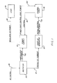
- Fig. 1 is a block diagram representation of a number of circuits related to a power supply 18 including a rectifier 20, a start-up generator 22, and logic control 24.
- the rectifier 20 Upon receiving an AC signal on a line 28, the rectifier 20 converts the AC signal into an unregulated DC power signal on a line 30 and to a trickle DC current on a line 32.
- the start-up generator 22 is provided the trickle DC current on the line 32 and generates an initial control logic power signal on a line 34 and provides this signal to the control logic 24.
- the control logic then provides a control signal on a line 36 to the power supply 18.
- the power supply 18 then starts up and begins generating a regulated DC power signal on a line 38 for a load 39 and a steady state control logic power signal on a line 40 to the control logic. 24.
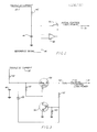
- Fig. 2 is a conceptual representation of a start-up circuit according to the present invention.
- a resistor 42 trickle charges a capacitor 44 until the magnitude of the voltage across the capacitor equals the magnitude of the voltage of a reference signal on a line 46.
- a comparator 48 closes a switch 50 and the capacitor 44 then transfers the charge stored in the capacitor via the initial control logic power signal line 34 to the control logic 24, as in Fig. 1.
- Fig. 3 is a schematic diagram of a start-up circuit, according to the present invention.
- the resistor 42 trickle charges the capacitor 44 until the charge stored on the capacitor 44 reaches the zener knee of a zener diode 52.
- a metal oxide semiconductor field effect transistor (MOSFET) 54 and a transistor 56 are held off by a resistor 58 and a resistor 60, respectively.
- MOSFET metal oxide semiconductor field effect transistor
- the zener diode 52 conducts current through the base emitter junction of the transistor 56.
- the transistor 56 then turns on and pulls the gate of the MOSFET 54 to ground, thereby biasing the MOSFET 54 on.
- a resistor 62 limits the peak current which the MOSFET 54 sees from the control logic 24.
- a diode 66 is back biased by the steady state control logic power on the line 40 so that the control logic side of the diode has a higher voltage than the start-up circuit side of the diode. In essence, the diode 66 is "open circuited" so that no current flows from the control logic 24 back into the start-up generator 22.
- elements 54 and 56 in Fig. 3 are shown as a MOSFET and transistor respectively, one skilled in the art would understand that other types of switches could be substituted for the element 54 or 56 with only minor modifications to the circuitry shown in Fig. 3. If for example, a bipolar transistor is used instead of a MOSFET for element 54, then a resistor must be placed between the collector of the transistor 56 and at the junction of the MOSFET 54 base and the resistor.
Landscapes
- Engineering & Computer Science (AREA)
- Power Engineering (AREA)
- Physics & Mathematics (AREA)
- Electromagnetism (AREA)
- General Physics & Mathematics (AREA)
- Radar, Positioning & Navigation (AREA)
- Automation & Control Theory (AREA)
- Control Of Voltage And Current In General (AREA)
- Rectifiers (AREA)
- Dc-Dc Converters (AREA)
Applications Claiming Priority (2)
| Application Number | Priority Date | Filing Date | Title |
|---|---|---|---|
| US6069187A | 1987-06-11 | 1987-06-11 | |
| US60691 | 1997-09-23 |
Publications (1)
| Publication Number | Publication Date |
|---|---|
| EP0295197A1 true EP0295197A1 (fr) | 1988-12-14 |
Family
ID=22031167
Family Applications (1)
| Application Number | Title | Priority Date | Filing Date |
|---|---|---|---|
| EP88630111A Withdrawn EP0295197A1 (fr) | 1987-06-11 | 1988-06-09 | Circuit de démarrage pour une alimentation électrique |
Country Status (2)
| Country | Link |
|---|---|
| EP (1) | EP0295197A1 (fr) |
| JP (1) | JPS6448112A (fr) |
Cited By (3)
| Publication number | Priority date | Publication date | Assignee | Title |
|---|---|---|---|---|
| RU2207695C2 (ru) * | 2001-07-10 | 2003-06-27 | Государственное унитарное предприятие "Всероссийский научно-исследовательский институт "Сигнал" | Конвертор |
| CN111755035A (zh) * | 2020-06-03 | 2020-10-09 | 深圳金茂电子有限公司 | 一种电源芯片管理系统及方法 |
| CN113126684A (zh) * | 2019-12-30 | 2021-07-16 | 西门子(深圳)磁共振有限公司 | 高压负压线性稳压器及具备其的磁共振成像设备 |
Citations (1)
| Publication number | Priority date | Publication date | Assignee | Title |
|---|---|---|---|---|
| US4246634A (en) * | 1979-03-07 | 1981-01-20 | Ann Arbor Terminals, Inc. | Start-up circuit for switch mode power supply |
-
1988
- 1988-06-09 EP EP88630111A patent/EP0295197A1/fr not_active Withdrawn
- 1988-06-10 JP JP63143456A patent/JPS6448112A/ja active Pending
Patent Citations (1)
| Publication number | Priority date | Publication date | Assignee | Title |
|---|---|---|---|---|
| US4246634A (en) * | 1979-03-07 | 1981-01-20 | Ann Arbor Terminals, Inc. | Start-up circuit for switch mode power supply |
Non-Patent Citations (1)
| Title |
|---|
| IBM TECHNICAL DISCLOSURE BULLETIN, vol. 13, no. 9, February 1971, pages 2763-2764, New York, US; W.A. MOORMAN: "Transistor switching regulator start circuit * |
Cited By (3)
| Publication number | Priority date | Publication date | Assignee | Title |
|---|---|---|---|---|
| RU2207695C2 (ru) * | 2001-07-10 | 2003-06-27 | Государственное унитарное предприятие "Всероссийский научно-исследовательский институт "Сигнал" | Конвертор |
| CN113126684A (zh) * | 2019-12-30 | 2021-07-16 | 西门子(深圳)磁共振有限公司 | 高压负压线性稳压器及具备其的磁共振成像设备 |
| CN111755035A (zh) * | 2020-06-03 | 2020-10-09 | 深圳金茂电子有限公司 | 一种电源芯片管理系统及方法 |
Also Published As
| Publication number | Publication date |
|---|---|
| JPS6448112A (en) | 1989-02-22 |
Similar Documents
| Publication | Publication Date | Title |
|---|---|---|
| US4246634A (en) | Start-up circuit for switch mode power supply | |
| US4754385A (en) | Two transistor flyback switching converter with current sensing for discontinuous operation | |
| US4607208A (en) | Battery charger | |
| US4809150A (en) | DC to DC converter with feed forward and feed back regulation | |
| US6359794B1 (en) | Battery backup power supply | |
| US3323034A (en) | Switching techniques in regulated d. c. power supplies | |
| US4035716A (en) | Super compensated voltage control of redundant D.C. power supplies | |
| US4870553A (en) | Double-switched flyback power-converter | |
| EP0124210B1 (fr) | Alimentation de puissance avec convertisseur à récupération commandé par courant | |
| EP0384680A2 (fr) | Circuit à commutation | |
| US3343059A (en) | Semiconductor generator voltage regulator system | |
| US4215392A (en) | Inverter power supply | |
| GB2141563A (en) | Switching regulator off-line starting circuit | |
| US3214599A (en) | Voltage regulator for d.c. generator | |
| WO1986001048A1 (fr) | Alimentation electrique a commutation | |
| JPH1028379A (ja) | 0ボルト電圧における複合ブリッジの制御 | |
| US4277824A (en) | Start-up circuit | |
| US4825350A (en) | Method and apparatus for detecting a reduction in the input voltage to a power supply | |
| US3898549A (en) | Variable duty cycle balanced DC/DC power converter | |
| US4484256A (en) | Constant current density high voltage power supply | |
| EP0247407B1 (fr) | Alimentation de puissance en mode à découpage | |
| US6222743B1 (en) | Power factor correction circuit | |
| US5391978A (en) | Feedback loss protection arrangement in a power supply | |
| JPS626872Y2 (fr) | ||
| US4410847A (en) | Voltage regulator |
Legal Events
| Date | Code | Title | Description |
|---|---|---|---|
| PUAI | Public reference made under article 153(3) epc to a published international application that has entered the european phase |
Free format text: ORIGINAL CODE: 0009012 |
|
| AK | Designated contracting states |
Kind code of ref document: A1 Designated state(s): DE FR GB IT |
|
| STAA | Information on the status of an ep patent application or granted ep patent |
Free format text: STATUS: THE APPLICATION IS DEEMED TO BE WITHDRAWN |
|
| 18D | Application deemed to be withdrawn |
Effective date: 19890615 |