EP0295201A1 - Spreizdübel mit begrenzter Spreizung - Google Patents
Spreizdübel mit begrenzter Spreizung Download PDFInfo
- Publication number
- EP0295201A1 EP0295201A1 EP88810277A EP88810277A EP0295201A1 EP 0295201 A1 EP0295201 A1 EP 0295201A1 EP 88810277 A EP88810277 A EP 88810277A EP 88810277 A EP88810277 A EP 88810277A EP 0295201 A1 EP0295201 A1 EP 0295201A1
- Authority
- EP
- European Patent Office
- Prior art keywords
- expansion
- expansion sleeve
- stop shoulder
- area
- sleeve
- Prior art date
- Legal status (The legal status is an assumption and is not a legal conclusion. Google has not performed a legal analysis and makes no representation as to the accuracy of the status listed.)
- Granted
Links
- 230000007704 transition Effects 0.000 claims description 3
- 238000006073 displacement reaction Methods 0.000 description 3
- 238000000034 method Methods 0.000 description 2
- 230000004323 axial length Effects 0.000 description 1
- 230000006378 damage Effects 0.000 description 1
- 230000003247 decreasing effect Effects 0.000 description 1
- 238000010586 diagram Methods 0.000 description 1
Images

Classifications
-
- F—MECHANICAL ENGINEERING; LIGHTING; HEATING; WEAPONS; BLASTING
- F16—ENGINEERING ELEMENTS AND UNITS; GENERAL MEASURES FOR PRODUCING AND MAINTAINING EFFECTIVE FUNCTIONING OF MACHINES OR INSTALLATIONS; THERMAL INSULATION IN GENERAL
- F16B—DEVICES FOR FASTENING OR SECURING CONSTRUCTIONAL ELEMENTS OR MACHINE PARTS TOGETHER, e.g. NAILS, BOLTS, CIRCLIPS, CLAMPS, CLIPS OR WEDGES; JOINTS OR JOINTING
- F16B13/00—Dowels or other devices fastened in walls or the like by inserting them in holes made therein for that purpose
- F16B13/04—Dowels or other devices fastened in walls or the like by inserting them in holes made therein for that purpose with parts gripping in the hole or behind the reverse side of the wall after inserting from the front
- F16B13/06—Dowels or other devices fastened in walls or the like by inserting them in holes made therein for that purpose with parts gripping in the hole or behind the reverse side of the wall after inserting from the front combined with expanding sleeve
- F16B13/063—Dowels or other devices fastened in walls or the like by inserting them in holes made therein for that purpose with parts gripping in the hole or behind the reverse side of the wall after inserting from the front combined with expanding sleeve by the use of an expander
- F16B13/066—Dowels or other devices fastened in walls or the like by inserting them in holes made therein for that purpose with parts gripping in the hole or behind the reverse side of the wall after inserting from the front combined with expanding sleeve by the use of an expander fastened by extracting a separate expander-part, actuated by the screw, nail or the like
Definitions
- the invention relates to an expansion dowel with an expansion sleeve that has a longitudinally slotted area from the front end and a truncated cone-shaped expansion body that can be drawn into this area from the front end, the expansion sleeve having a bore that extends within the slotted area corresponding to the expansion body toward the front end flared.
- Expansion anchors of the type mentioned, for example from DE-PS 2 536 137 have a post-expansion behavior in use and are used primarily in the middle and upper load range. For certain applications, such as fastenings in the crack-prone tensile zone of a building, these dowels cannot be used without further ado. If a crack runs directly through the borehole, it can be widened so much when the anchor is expanded that the anchorage value of the anchor drops significantly. In extreme cases, this over-spreading of the dowel can also lead to chipping or destruction of the structure and thus to failure of the dowel.
- the invention has for its object to provide an expansion dowel that has a limited expansion behavior.
- this is achieved in that within the slotted area, subsequent to the conical extension towards the rear end, a cylindrical bore region adjoins, the diameter of which corresponds to the smallest diameter of the conical extension and exceeds the bore of the expansion sleeve.
- the expansion body As long as the expansion body is in the conically widening area of the bore of the expansion sleeve, there is a relatively large expansion of the tensile load Expansion sleeve. Due to the conicity of the expanding area corresponding to that of the expansion body, this expansion of the expansion sleeve takes place approximately parallel to the longitudinal axis of the expansion anchor. If the expansion body reaches the cylindrical bore area of the expansion sleeve, the expansion sleeve is subsequently expanded when there is tensile load on the expansion body. However, this is less than if the expansion body is located in the expanding area of the expansion sleeve. When the dowel is pre-spread, this is also noticeable by a smaller increase in the tensile force to be applied or the torque to be applied. The expansion path is limited by the axial length of the cylindrical area.
- the transition from the cylindrical bore area to the bore of the expansion sleeve as a stop shoulder for the expansion body. If the expansion body already hits the stop shoulder during pre-expansion, this is noticeable by a sudden sharp increase in the pre-tensioning force to be applied. By partially deforming the stop shoulder, an overstressing of the expansion anchor can be avoided.
- the stop shoulder advantageously runs essentially perpendicular to the longitudinal axis of the dowel, so that a flat contact surface is created for the expansion body.
- the axial pressure occurring when the expansion body comes up against the stop shoulder is distributed uniformly over the circumference of the rear end face of the expansion body.
- the stop shoulder is expediently curved in a concave manner. At the end of the re-expansion process, this enables the expansion body to gently run up against the stop shoulder. The expansion body thus slides over the concavely curved stop shoulder and at the same time becomes centered. In the case of a sharp-edged expanding body, there is initially only a line contact between the expanding body and the stop shoulder. By deformation of the expansion body on the one hand and the stop shoulder on the other hand, however, over time the surface of the expansion body rests on the expansion sleeve in the axial direction.
- the curvature of the stop shoulder can be constant or variable, the radius of curvature preferably decreasing in the direction of the rear end of the expansion sleeve.
- the stop shoulder is inclined to the longitudinal axis of the dowel. This inclination of the stop shoulder can be directed towards the front or rear end of the expansion sleeve. An inclination towards the front end of the expansion sleeve creates a conical countersink in the manner of a valve seat. If the inclination of the stop shoulder is directed towards the rear end of the expansion sleeve, an annular projection is formed on the stop shoulder, which can be deformed when the expanding body comes up. Such a deformation zone prevents the anchor from being overstressed.
- the length of the conical widening of the expansion sleeve expediently corresponds essentially to the length of the truncated cone-shaped expansion body.
- Such a dimensioning means that the expansion body is completely in the expansion sleeve at the end of the first expansion phase in the area of the conical widening.
- the foremost part of the expansion sleeve is then no longer in the area of the expansion body and can therefore deform back somewhat. This further facilitates the retraction of the expansion body in the second phase.
- the length of the cylindrical bore region advantageously corresponds essentially to the length of the truncated cone-shaped expansion body. If the expansion body at the rear end of the cylindrical bore area System comes, it is therefore completely in the cylindrical bore area and outside the conical expansion of the expansion sleeve. The maximum expansion of the expansion sleeve is thus in the transition area between the conical expansion and the cylindrical bore area. This results in a good, even distribution of the spreading pressure in the borehole and prevents overloading of the receiving material.
- the expansion dowel according to the invention shown in FIGS. 1 to 3 essentially consists of an expansion sleeve, generally designated 1, with a front end 1a and a rear end 1b, and an expansion body which can be drawn into the front end 1a of the expansion sleeve 1, generally designated 2.
- the expansion sleeve 1 has a through bore 1c and also extends from the front end 1a part of the length of the expansion sleeve 1 extending longitudinal slots 1d.
- the foremost part of the bore 1c is designed as a conical extension 1e with a diameter increasing towards the front end 1a.
- the conical extension 1e is adjoined by a cylindrical bore region 1f, the diameter of which corresponds to the smallest diameter of the conical extension 1e.
- the cylindrical bore area 1f exceeds the diameter of the bore 1c of the expansion sleeve 1, so that a stop shoulder 1g is formed at the rear end of the cylindrical bore area 1f.
- the expansion sleeve 1 is inserted into a borehole 3a of a receiving material, designated overall by 3. After the expansion dowel has been inserted into the receiving material 3, a screw, generally designated 4, is inserted through a component 5 to be fastened into the expansion sleeve 1 and screwed into an internal thread 2a of the expansion body 2.
- a washer 6 is arranged between a head 4a of the screw 4 and the component 5 to be fastened.
- the expansion body 2 has been drawn into the expansion sleeve 1 up to the rear end of the conical extension 1e. If an additional load now occurs on the screw 4, the expansion body 2 is also drawn into the cylindrical bore area 1f. The end of this process is shown in Fig. 3. The rear end of the expansion body 2 has accrued on the stop shoulder 1g. The maximum possible radial expandability of the expansion sleeve 1 is thus achieved. If the screw 4 is subjected to further tensile loads, only the stop shoulder 1g can be deformed.
- FIGS. 5 and 6 show further expansion sleeves, designated overall by 11 and 21. These differ from the embodiment shown in FIGS. 1 to 3 only in the design of the stop shoulder. Corresponding reference numbers have been increased by ten or twenty.
- the stop shoulder 11g shown in FIG. 5 is concavely curved. With such a configuration of the stop shoulder 11g, the expansion of the expansion body 2 on the stop shoulder 11g can be controlled, for example, so that it does not take place hard and suddenly, as in the case of the stop shoulder 1g, which runs essentially perpendicular to the longitudinal axis of the dowel, but softly and gradually.
- the radius of curvature of the stop shoulder 11g can remain constant or change in the entire area.
- the stop shoulder 21g is inclined to the longitudinal axis of the dowel.
- the inclination of the stop shoulder 21g is directed in such a way that a kind of undercut or a projection is formed. This projection can be deformed when the expansion body 2 comes up.
- This embodiment also results in a soft emergence of the expansion body 2 on the expansion sleeve 21.
Landscapes
- General Engineering & Computer Science (AREA)
- Engineering & Computer Science (AREA)
- Mechanical Engineering (AREA)
- Dowels (AREA)
- Joining Of Building Structures In Genera (AREA)
- Preparation Of Fruits And Vegetables (AREA)
- Processing Of Stones Or Stones Resemblance Materials (AREA)
- Orthopedics, Nursing, And Contraception (AREA)
- Finger-Pressure Massage (AREA)
- Road Signs Or Road Markings (AREA)
- Thermotherapy And Cooling Therapy Devices (AREA)
- Closures For Containers (AREA)
- Coating Apparatus (AREA)
- Pharmaceuticals Containing Other Organic And Inorganic Compounds (AREA)
Abstract
Description
- Die Erfindung betrifft einen Spreizdübel mit einer einen vom vorderen Ende her längsgeschlitzten Bereich aufweisenden Spreizhülse und einem vom vorderen Ende her in diesen Bereich einziehbaren, kegelstumpfförmigen Spreizkörper, wobei die Spreizhülse eine Bohrung aufweist, die sich innerhalb des geschlitzten Bereiches entsprechend dem Spreizkörper zum vorderen Ende hin konisch erweitert.
- Spreizdübel der genannten, beispielsweise aus der DE-PS 2 536 137 bekannten Art weisen im Einsatz ein Nachspreizverhalten auf und werden vor allem im mittleren und oberen Lastbereich eingesetzt. Für bestimmte Anwendungen, wie beispielsweise Befestigungen in der rissanfälligen Zugzone eines Bauwerkes, können diese Dübel jedoch nicht ohne weiteres verwendet werden. Falls ein Riss direkt durch das Bohrloch verläuft, kann dieser bei der Nachspreizung des Dübels so stark aufgeweitet werden, dass der Verankerungswert des Dübels stark absinkt. Im Extremfall kann dieses Ueberspreizen des Dübels auch zu Abplatzungen oder Zerstörungen des Bauwerkes und dadurch zu einem Ausfall des Dübels führen.
- Der Erfindung liegt die Aufgabe zugrunde, einen Spreizdübel zu schaffen, der ein begrenztes Nachspreizverhalten aufweist.
- Gemäss der Erfindung wird dies dadurch erreicht, dass sich innerhalb des geschlitzten Bereiches, anschliessend an die konische Erweiterung zum rückwärtigen Ende hin ein zylindrischer Bohrungsbereich anschliesst, dessen Durchmesser dem kleinsten Durchmesser der konischen Erweiterung entspricht und die Bohrung der Spreizhülse übersteigt.
- Solange sich der Spreizkörper in dem sich konisch erweiternden Bereich der Bohrung der Spreizhülse befindet, erfolgt bei Zugbelastung eine relativ starke Aufweitung der Spreizhülse. Durch die, derjenigen des Spreizkörpers entsprechende Konizität des sich erweiternden Bereiches erfolgt diese Aufweitung der Spreizhülse etwa parallel zur Längsachse des Spreizdübels. Gelangt der Spreizkörper in den zylindrischen Bohrungsbereich der Spreizhülse, so erfolgt zwar bei Zugbelastung am Spreizkörper auch eine Nachspreizung der Spreizhülse. Diese ist jedoch geringer, als wenn sich der Spreizkörper im sich erweiternden Bereich der Spreizhülse befindet. Beim Vorspreizen des Dübels macht sich dies auch durch ein geringeres Ansteigen der aufzubringenden Zugkraft, bzw des aufzubringenden Drehmomentes bemerkbar. Der Nachspreizweg ist durch die axiale Länge des zylindrischen Bereiches begrenzt.
- Um eine definierte Endlage des Spreizkörpers und somit einen definierten maximalen Spreizzustand des Spreizdübels zu erreichen, ist es zweckmässig, den Uebergang vom zylindrischen Bohrungsbereich zur Bohrung der Spreizhülse als Anschlagschulter für den Spreizkörper auszubilden. Falls der Spreizkörper bereits beim Vorspreizen an der Anschlagschulter aufläuft, so macht sich dies durch ein plötzliches starkes Ansteigen der aufzubringenden Vorspannkraft bemerkbar. Durch teilweise Verformbarkeit der Anschlagschulter kann eine Ueberbeanspruchung des Spreizdübels vermieden werden.
- Vorteilhafterweise verläuft die Anschlagschulter im wesentlichen senkrecht zur Dübellängsachse, so dass eine plane Auflauffläche für den Spreizkörper entsteht. Somit wird der beim Auflaufen des Spreizkörpers an der Anschlagschulter auftretende Axialdruck gleichmässig über den Umfang der rückwärtigen Stirnseite des Spreizkörpers verteilt.
- Die Anschlagschulter ist zweckmässigerweise konkav gekrümmt ausgebildet. Dies ermöglicht am Ende des Nachspreizvorganges ein sanftes Auflaufen des Spreizkörpers an der Anschlagschulter. Der Spreizkörper gleitet somit über die konkav gekrümmt ausgebildete Anschlagschulter und wird dabei gleichzeitig zentriert. Bei scharfkantig ausgebildetem Spreizkörper erfolgt dabei zunächst nur eine Linienberührung zwischen dem Spreizkörper und der Anschlagschulter. Durch Verformung des Spreizkörpers einerseits und der Anschlagschulter andererseits entsteht jedoch mit der Zeit eine flächige Auflage des Spreizkörpers an der Spreizhülse in axialer Richtung. Die Krümmung der Anschlagschulter kann konstant oder veränderlich sein, wobei vorzugsweise der Krümmungsradius in Richtung des rückwärtigen Endes der Spreizhülse abnimmt.
- Eine weitere vorteilhafte Ausführung besteht darin, dass die Anschlagschulter zur Dübellängsachse geneigt verläuft. Diese Neigung der Anschlagschulter kann zum vorderen oder zum rückwärtigen Ende der Spreizhülse gerichtet sein. Durch eine zum vorderen Ende der Spreizhülse gerichtete Neigung entsteht eine kegelige Ansenkung nach Art eines Ventilsitzes. Ist die Neigung der Anschlagschulter gegen das rückwärtige Ende der Spreizhülse gerichtet, so entsteht an der Anschlagschulter ein ringförmiger Vorsprung, welcher beim Auflaufen des Spreizkörpers verformt werden kann. Eine solche Verformungszone verhindert eine Ueberbeanspruchung des Dübels.
- Zweckmässigerweise entspricht die Länge der konischen Erweiterung der Spreizhülse im wesentlichen der Länge des kegelstumpfförmigen Spreizkörpers. Durch eine solche Dimensionierung befindet sich der Spreizkörper am Ende der ersten Spreizphase im Bereich der konischen Erweiterung vollständig in der Spreizhülse. Beim weiteren Einziehen des Spreizkörpers in die Spreizhülse ist dann der vorderste Teil der Spreizhülse nicht mehr im Bereich des Spreizkörpers und kann sich somit etwas zurückverformen. Somit wird das weitere Einziehen des Spreizkörpers in der zweiten Phase erleichtert.
- Ferner entspricht vorteilhafterweise die Länge des zylindrischen Bohrungsbereiches im wesentlichen der Länge des kegelstumpfförmigen Spreizkörpers. Wenn der Spreizkörper am rückwärtigen Ende des zylindrischen Bohrungsbereiches zur Anlage kommt, befindet er sich somit vollständig im zylindrischen Bohrungsbereich und ausserhalb der konischen Erweiterung der Spreizhülse. Die maximale Aufweitung der Spreizhülse befindet sich somit im Uebergangsbereich zwischen der konischen Erweiterung und dem zylindrischen Bohrungsbereich. Dies ergibt eine gute, gleichmässige Verteilung des Spreizdruckes im Bohrloch und verhindert Ueberbelastungen des Aufnahmematerials.
- Die Erfindung soll nachstehend anhand der sie beispielsweise wiedergebenden Zeichnungen näher erläutert werden. Es zeigen:
- Fig. 1 einen erfindungsgemässen Spreizdübel, in ungespreiztem Zustand,
- Fig. 2 den Spreizdübel gemäss Fig. 1, in teilweise gespreiztem Zustand,
- Fig. 3 den Spreizdübel gemäss Fig. 1 und 2, in maximal gespreiztem Zustand,
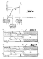
- Fig. 4 eine Belastungscharakeristik des erfindungsgemässen Dübels gemäss Fig. 1 bis 3,
- Fig. 5 eine andere Spreizhülse eines erfindungsgemässen Dübels,
- Fig. 6 eine weitere Spreizhülse eines erfindungsgemässen Dübels.
- Der aus den Fig. 1 bis 3 ersichtliche, erfindungsgemässe Spreizdübel besteht im wesentlichen aus einer insgesamt mit 1 bezeichneten Spreizhülse mit einem vorderen Ende 1a und einem rückwärtigen Ende 1b sowie einer in das vordere Ende 1a der Spreizhülse 1 einziehbaren, insgesamt mit 2 bezeichneten Spreizkörper. Die Spreizhülse 1 weist eine durchgehende Bohrung 1c sowie vom vorderen Ende 1a ausgehende, sich über einen Teil der Länge der Spreizhülse 1 erstreckende Längsschlitze 1d auf. Der vorderste Teil der Bohrung 1c ist als konische Erweiterung 1e mit sich gegen das vordere Ende 1a vergrösserndem Durchmesser ausgebildet. Zum rückwärtigen Ende 1b hin schliesst sich an die konische Erweiterung 1e ein zylindrischer Bohrungsbereich 1f an, dessen Durchmesser dem kleinsten Durchmesser der konischen Erweiterung 1e entspricht. Der zylindrische Bohrungsbereich 1f übersteigt jedoch den Durchmesser der Bohrung 1c der Spreizhülse 1, so dass am rückwärtigen Ende des zylindrischen Bohrungsbereiches 1f eine Anschlagschulter 1g gebildet wird. Die Spreizhülse 1 ist in ein Bohrloch 3a eines insgesamt mit 3 bezeichneten Aufnahmematerials eingesetzt. Nach dem Einsetzen des Spreizdübels in das Aufnahmematerial 3 ist eine insgesamt mit 4 bezeichnete Schraube durch ein zu befestigendes Bauteil 5 hindurch in die Spreizhülse 1 eingeführt und in ein Innengewinde 2a des Spreizkörpers 2 eingeschraubt. Zwischen einem Kopf 4a der Schraube 4 und dem zu befestigenden Bauteil 5 ist eine Unterlagscheibe 6 angeordnet. Durch Aufbringen eines Drehmomentes am Kopf 4a der Schraube 4 kann der Spreizkörper 2 in die Spreizhülse 1 eingezogen und der Spreizdübel somit vorgespreizt werden. Bei nachfolgender Belastung an Kopf 4a der Schraube 4 erfolgt eine Nachspreizung des Dübels.
- In Fig. 2 ist der Spreizkörper 2 bis an das rückwärtige Ende der konischen Erweiterung 1e in die Spreizhülse 1 eingezogen worden. Tritt nun an der Schraube 4 eine zusätzliche Belastung auf, so wird der Spreizkörper 2 auch in den zylindrischen Bohrungsbereich 1f hineingezogen. Das Ende dieses Vorganges ist in Fig. 3 dargestellt. Dabei ist das rückwärtige Endes des Spreizkörpers 2 an der Anschlagschulter 1g aufgelaufen. Somit ist die maximal mögliche radiale Aufweitbarkeit der Spreizhülse 1 erreicht. Bei weiterer Zugbelastung der Schraube 4 kann nur noch die Anschlagschulter 1g verformt werden.
- Fig. 4 zeigt den Verlauf des Verschiebeweges s in Abhängigkeit von der aufgebrachten Zugbelastung Z. Wie das Diagramm zeigt, ist der Verschiebeweg etwa proportional zur Zugbelastung, solange sich der Spreizkörper im Bereich der konischen Erweiterung befindet (Teil A der Kurve). Gelangt der Spreizkörper in den zylindrischen Bohrungsbereich, so wird mit geringer zusätzlicher Belastung ein wesentlich grösserer Verschiebeweg erreicht (Teil B der Kurve). Gelangt der Spreizkörper dann an der Anschlagschulter zur Anlage, so erfolgt nochmals ein starker Anstieg der aufzubringenden Belastung (Teil C der Kurve). Dieser Anstieg ist beim Spreizen des Dübels deutlich spürbar.
- Fig. 5 und 6 zeigen weitere, insgesamt mit 11 und 21 bezeichnete Spreizhülsen. Diese unterscheiden sich von der in Fig. 1 bis 3 dargestellten Ausführung nur durch die Ausbildung der Anschlagschulter. Entsprechende Bezugsziffern sind um zehn bzw zwanzig erhöht. Die in Fig. 5 dargestellte Anschlagschulter 11g ist konkav gekrümmt ausgebildet. Durch eine solche Ausbildung der Anschlagschulter 11g kann das Auflaufen des Spreizkörpers 2 an der Anschlagschulter 11g beispielsweise so gesteuert werden, dass es nicht wie bei der im wesentlichen senkrecht zur Dübellängsachse verlaufenden Anschlagschulter 1g hart und plötzlich, sondern weich und allmählich erfolgt. Der Krümmungsradius der Anschlagschulter 11g kann im gesamten Bereich konstant bleiben oder sich verändern.
- Bei der in Fig. 6 dargestellten, insgesamt mit 21 bezeichneten Spreizhülse verläuft die Anschlagschulter 21g zur Dübellängsachse geneigt. Die Neigung der Anschlagschulter 21g ist so gerichtet, dass dadurch eine Art Hinterschnitt, bzw ein Vorsprung gebildet wird. Dieser Vorsprung kann beim Auflaufen des Spreizkörpers 2 verformt werden. Auch diese Ausführung ergibt somit ein weiches Auflaufen des Spreizkörpers 2 an der Spreizhülse 21.
Claims (7)
Priority Applications (1)
| Application Number | Priority Date | Filing Date | Title |
|---|---|---|---|
| AT88810277T ATE52311T1 (de) | 1987-06-09 | 1988-04-29 | Spreizduebel mit begrenzter spreizung. |
Applications Claiming Priority (2)
| Application Number | Priority Date | Filing Date | Title |
|---|---|---|---|
| DE3719164 | 1987-06-09 | ||
| DE19873719164 DE3719164A1 (de) | 1987-06-09 | 1987-06-09 | Spreizduebel mit begrenzter spreizung |
Publications (2)
| Publication Number | Publication Date |
|---|---|
| EP0295201A1 true EP0295201A1 (de) | 1988-12-14 |
| EP0295201B1 EP0295201B1 (de) | 1990-04-25 |
Family
ID=6329300
Family Applications (1)
| Application Number | Title | Priority Date | Filing Date |
|---|---|---|---|
| EP88810277A Expired - Lifetime EP0295201B1 (de) | 1987-06-09 | 1988-04-29 | Spreizdübel mit begrenzter Spreizung |
Country Status (11)
| Country | Link |
|---|---|
| US (1) | US4869631A (de) |
| EP (1) | EP0295201B1 (de) |
| JP (2) | JPS63312503A (de) |
| AT (1) | ATE52311T1 (de) |
| AU (1) | AU605068B2 (de) |
| CA (1) | CA1303884C (de) |
| DE (2) | DE3719164A1 (de) |
| DK (1) | DK165065C (de) |
| ES (1) | ES2014511B3 (de) |
| FI (1) | FI90280C (de) |
| MX (1) | MX169082B (de) |
Cited By (1)
| Publication number | Priority date | Publication date | Assignee | Title |
|---|---|---|---|---|
| EP0503677A3 (en) * | 1991-03-14 | 1993-01-13 | Maechtle Gmbh | Heavy duty anchor |
Families Citing this family (8)
| Publication number | Priority date | Publication date | Assignee | Title |
|---|---|---|---|---|
| US5033909A (en) * | 1990-04-27 | 1991-07-23 | Ingersoll-Rand Company | Coupling for anchor rod and sleeve |
| DE19820140A1 (de) * | 1998-05-06 | 1999-11-11 | Adolf Wuerth Gmbh & Co Kg | Befestigung von Masten für Ampeln oder dergleichen |
| DE19921148A1 (de) * | 1999-05-07 | 2000-11-09 | Hilti Ag | Schienenfuß für ein Diamantschneidesystem |
| US20020194718A1 (en) * | 2001-06-21 | 2002-12-26 | David Yekutiely | Anchoring system and methods therefor |
| DE10134604A1 (de) * | 2001-07-17 | 2003-02-06 | Hilti Ag | Spreizdübel |
| FR2947592B1 (fr) * | 2009-07-06 | 2015-05-15 | Airbus Operations Sas | Dispositif de liaison mecanique d'au moins deux pieces a alesages coaxiaux |
| CN107366667A (zh) * | 2017-08-04 | 2017-11-21 | 索菲亚家居股份有限公司 | 快装连接件 |
| EP3536984A1 (de) * | 2018-03-05 | 2019-09-11 | HILTI Aktiengesellschaft | Spreizanker mit zusatzspreizkörper |
Citations (5)
| Publication number | Priority date | Publication date | Assignee | Title |
|---|---|---|---|---|
| CH483571A (de) * | 1967-11-22 | 1969-12-31 | Schmid Arthur | Dübel |
| DE2150572A1 (de) * | 1971-10-11 | 1973-04-19 | Willi Schober | Spreizduebel |
| AT328231B (de) * | 1972-10-11 | 1976-03-10 | Liebig Heinrich | Spreizdubel |
| EP0067751A2 (de) * | 1981-05-29 | 1982-12-22 | SHUR-LOK INTERNATIONAL S.A. Société dite: | Einrichtung zum Ein- und Festsetzen einer Schraube oder eines Bolzens in einer Sackbohrung |
| GB2139726A (en) * | 1983-05-12 | 1984-11-14 | Tucker Fasteners Ltd | Bolt anchor |
Family Cites Families (13)
| Publication number | Priority date | Publication date | Assignee | Title |
|---|---|---|---|---|
| US1755264A (en) * | 1929-02-25 | 1930-04-22 | American Bolt Anchor Corp | Means for anchoring bolts |
| US1959439A (en) * | 1931-12-02 | 1934-05-22 | Edward Ogden Company Inc J | Expansion shield or bolt anchor |
| US2319376A (en) * | 1942-08-24 | 1943-05-18 | Herman H Helbush | Rivet |
| GB906615A (en) * | 1960-03-31 | 1962-09-26 | Robert Kearsley Baker | Improvements in or relating to expansion sockets |
| CH433671A (de) * | 1964-06-12 | 1967-04-15 | Gerhard Anton | Vorrichtung zum Verbinden von Fenster- oder Türrahmen oder dergleichen mit dem Mauerwerk |
| JPS4843823U (de) * | 1971-09-27 | 1973-06-07 | ||
| DE2501925C3 (de) * | 1975-01-18 | 1979-07-26 | Heinrich B. 2800 Bremen Schaefers | Dübel |
| DE2536137C2 (de) * | 1975-08-13 | 1986-04-10 | Hilti Ag, Schaan | Spreizdübel |
| DE2834241A1 (de) * | 1978-08-04 | 1980-02-28 | Volker Hainke | Ankerbolzen |
| AU533341B2 (en) * | 1979-12-18 | 1983-11-17 | Volken Hainke | Foundation bolt |
| CH644190A5 (de) * | 1980-03-05 | 1984-07-13 | Julius Murbach | Duebel. |
| US4627775A (en) * | 1983-09-01 | 1986-12-09 | Huck Manufacturing Company | Blind fastener with grip compensating means |
| DE3335628A1 (de) * | 1983-09-30 | 1985-04-04 | Hilti Ag, Schaan | Spreizduebel mit einziehbarem spreizkoerper |
-
1987
- 1987-06-09 DE DE19873719164 patent/DE3719164A1/de not_active Withdrawn
-
1988
- 1988-04-29 AT AT88810277T patent/ATE52311T1/de not_active IP Right Cessation
- 1988-04-29 DE DE8888810277T patent/DE3860108D1/de not_active Expired - Fee Related
- 1988-04-29 ES ES88810277T patent/ES2014511B3/es not_active Expired - Lifetime
- 1988-04-29 EP EP88810277A patent/EP0295201B1/de not_active Expired - Lifetime
- 1988-05-27 DK DK292788A patent/DK165065C/da not_active IP Right Cessation
- 1988-05-31 US US07/200,640 patent/US4869631A/en not_active Expired - Lifetime
- 1988-06-01 CA CA000568346A patent/CA1303884C/en not_active Expired - Fee Related
- 1988-06-06 FI FI882654A patent/FI90280C/fi not_active IP Right Cessation
- 1988-06-07 AU AU17464/88A patent/AU605068B2/en not_active Ceased
- 1988-06-08 JP JP63139578A patent/JPS63312503A/ja active Pending
- 1988-06-08 MX MX011816A patent/MX169082B/es unknown
-
1996
- 1996-08-20 JP JP1996008382U patent/JP2572758Y2/ja not_active Expired - Lifetime
Patent Citations (5)
| Publication number | Priority date | Publication date | Assignee | Title |
|---|---|---|---|---|
| CH483571A (de) * | 1967-11-22 | 1969-12-31 | Schmid Arthur | Dübel |
| DE2150572A1 (de) * | 1971-10-11 | 1973-04-19 | Willi Schober | Spreizduebel |
| AT328231B (de) * | 1972-10-11 | 1976-03-10 | Liebig Heinrich | Spreizdubel |
| EP0067751A2 (de) * | 1981-05-29 | 1982-12-22 | SHUR-LOK INTERNATIONAL S.A. Société dite: | Einrichtung zum Ein- und Festsetzen einer Schraube oder eines Bolzens in einer Sackbohrung |
| GB2139726A (en) * | 1983-05-12 | 1984-11-14 | Tucker Fasteners Ltd | Bolt anchor |
Cited By (1)
| Publication number | Priority date | Publication date | Assignee | Title |
|---|---|---|---|---|
| EP0503677A3 (en) * | 1991-03-14 | 1993-01-13 | Maechtle Gmbh | Heavy duty anchor |
Also Published As
| Publication number | Publication date |
|---|---|
| CA1303884C (en) | 1992-06-23 |
| DE3719164A1 (de) | 1988-12-29 |
| DK292788D0 (da) | 1988-05-27 |
| DK165065C (da) | 1993-02-22 |
| JP2572758Y2 (ja) | 1998-05-25 |
| DE3860108D1 (de) | 1990-05-31 |
| MX169082B (es) | 1993-06-21 |
| FI90280B (fi) | 1993-09-30 |
| DK292788A (da) | 1988-12-10 |
| EP0295201B1 (de) | 1990-04-25 |
| FI882654A0 (fi) | 1988-06-06 |
| ES2014511B3 (es) | 1990-07-16 |
| DK165065B (da) | 1992-10-05 |
| ATE52311T1 (de) | 1990-05-15 |
| AU1746488A (en) | 1988-12-15 |
| AU605068B2 (en) | 1991-01-03 |
| US4869631A (en) | 1989-09-26 |
| JPH09274U (ja) | 1997-05-16 |
| FI882654L (fi) | 1988-12-10 |
| JPS63312503A (ja) | 1988-12-21 |
| FI90280C (fi) | 1994-01-10 |
Similar Documents
| Publication | Publication Date | Title |
|---|---|---|
| EP0308619B1 (de) | Spreizdübel | |
| DE3420375C2 (de) | Dübel | |
| EP0905385B1 (de) | Spreizdübel | |
| EP0318426B1 (de) | Spreizdübel mit Spreizhülse und einziehbarem Spreizkegel | |
| DE68908607T2 (de) | Blindniet. | |
| EP0308620A1 (de) | Spreizdübel | |
| DE2617191A1 (de) | Spreizduebel | |
| DE3329732A1 (de) | Spreizanker | |
| DE3346537A1 (de) | Spreizanker | |
| EP0295201B1 (de) | Spreizdübel mit begrenzter Spreizung | |
| EP0308594B1 (de) | Spreizdübel | |
| DE3413854C2 (de) | ||
| EP0733813B1 (de) | Spreizdübel | |
| EP0306681A1 (de) | Verfahren zum Verankern eines Spreizdübels | |
| EP0723085A1 (de) | Spreizdübel | |
| EP0612924B1 (de) | Spreizdübel mit Hülse und Spreizkörper | |
| EP0905386B1 (de) | Spreizdübel | |
| DE2435152A1 (de) | Spreizduebel | |
| EP0635645B1 (de) | Dübel | |
| EP0171354B1 (de) | Spreizdübel | |
| EP0503677A2 (de) | Schwerlastanker | |
| CH663451A5 (de) | Spreizduebel mit keilfoermigem spreizelement. | |
| DE3538298A1 (de) | Schlagspreizduebel fuer die verankerung in konisch nach innen erweiterten bohrloechern | |
| DD267536A5 (de) | Duebel mit spreizhuelse | |
| DE2914074A1 (de) | Bauwerksanker fuer eine verankerung in einer bohrung |
Legal Events
| Date | Code | Title | Description |
|---|---|---|---|
| PUAI | Public reference made under article 153(3) epc to a published international application that has entered the european phase |
Free format text: ORIGINAL CODE: 0009012 |
|
| AK | Designated contracting states |
Kind code of ref document: A1 Designated state(s): AT BE CH DE ES FR GB IT LI NL SE |
|
| 17P | Request for examination filed |
Effective date: 19890113 |
|
| 17Q | First examination report despatched |
Effective date: 19890814 |
|
| GRAA | (expected) grant |
Free format text: ORIGINAL CODE: 0009210 |
|
| AK | Designated contracting states |
Kind code of ref document: B1 Designated state(s): AT BE CH DE ES FR GB IT LI NL SE |
|
| REF | Corresponds to: |
Ref document number: 52311 Country of ref document: AT Date of ref document: 19900515 Kind code of ref document: T |
|
| ITF | It: translation for a ep patent filed | ||
| REF | Corresponds to: |
Ref document number: 3860108 Country of ref document: DE Date of ref document: 19900531 |
|
| ET | Fr: translation filed | ||
| GBT | Gb: translation of ep patent filed (gb section 77(6)(a)/1977) | ||
| PLBE | No opposition filed within time limit |
Free format text: ORIGINAL CODE: 0009261 |
|
| STAA | Information on the status of an ep patent application or granted ep patent |
Free format text: STATUS: NO OPPOSITION FILED WITHIN TIME LIMIT |
|
| 26N | No opposition filed | ||
| ITTA | It: last paid annual fee | ||
| EAL | Se: european patent in force in sweden |
Ref document number: 88810277.9 |
|
| PGFP | Annual fee paid to national office [announced via postgrant information from national office to epo] |
Ref country code: SE Payment date: 19990301 Year of fee payment: 12 Ref country code: BE Payment date: 19990301 Year of fee payment: 12 |
|
| PGFP | Annual fee paid to national office [announced via postgrant information from national office to epo] |
Ref country code: NL Payment date: 19990429 Year of fee payment: 12 |
|
| PGFP | Annual fee paid to national office [announced via postgrant information from national office to epo] |
Ref country code: FR Payment date: 20000411 Year of fee payment: 13 |
|
| PGFP | Annual fee paid to national office [announced via postgrant information from national office to epo] |
Ref country code: AT Payment date: 20000412 Year of fee payment: 13 |
|
| PGFP | Annual fee paid to national office [announced via postgrant information from national office to epo] |
Ref country code: ES Payment date: 20000419 Year of fee payment: 13 |
|
| PGFP | Annual fee paid to national office [announced via postgrant information from national office to epo] |
Ref country code: GB Payment date: 20000426 Year of fee payment: 13 |
|
| PGFP | Annual fee paid to national office [announced via postgrant information from national office to epo] |
Ref country code: CH Payment date: 20000427 Year of fee payment: 13 |
|
| PG25 | Lapsed in a contracting state [announced via postgrant information from national office to epo] |
Ref country code: SE Free format text: LAPSE BECAUSE OF NON-PAYMENT OF DUE FEES Effective date: 20000430 Ref country code: BE Free format text: LAPSE BECAUSE OF NON-PAYMENT OF DUE FEES Effective date: 20000430 |
|
| BERE | Be: lapsed |
Owner name: HILTI A.G. Effective date: 20000430 |
|
| PG25 | Lapsed in a contracting state [announced via postgrant information from national office to epo] |
Ref country code: NL Free format text: LAPSE BECAUSE OF NON-PAYMENT OF DUE FEES Effective date: 20001101 |
|
| EUG | Se: european patent has lapsed |
Ref document number: 88810277.9 |
|
| NLV4 | Nl: lapsed or anulled due to non-payment of the annual fee |
Effective date: 20001101 |
|
| PG25 | Lapsed in a contracting state [announced via postgrant information from national office to epo] |
Ref country code: GB Free format text: LAPSE BECAUSE OF NON-PAYMENT OF DUE FEES Effective date: 20010429 Ref country code: AT Free format text: LAPSE BECAUSE OF NON-PAYMENT OF DUE FEES Effective date: 20010429 |
|
| PG25 | Lapsed in a contracting state [announced via postgrant information from national office to epo] |
Ref country code: FR Free format text: THE PATENT HAS BEEN ANNULLED BY A DECISION OF A NATIONAL AUTHORITY Effective date: 20010430 Ref country code: ES Free format text: LAPSE BECAUSE OF NON-PAYMENT OF DUE FEES Effective date: 20010430 |
|
| PG25 | Lapsed in a contracting state [announced via postgrant information from national office to epo] |
Ref country code: LI Free format text: LAPSE BECAUSE OF NON-PAYMENT OF DUE FEES Effective date: 20010528 Ref country code: CH Free format text: LAPSE BECAUSE OF NON-PAYMENT OF DUE FEES Effective date: 20010528 |
|
| REG | Reference to a national code |
Ref country code: CH Ref legal event code: PL |
|
| GBPC | Gb: european patent ceased through non-payment of renewal fee |
Effective date: 20010429 |
|
| REG | Reference to a national code |
Ref country code: FR Ref legal event code: ST |
|
| PGFP | Annual fee paid to national office [announced via postgrant information from national office to epo] |
Ref country code: DE Payment date: 20020508 Year of fee payment: 15 |
|
| REG | Reference to a national code |
Ref country code: ES Ref legal event code: FD2A Effective date: 20030203 |
|
| PG25 | Lapsed in a contracting state [announced via postgrant information from national office to epo] |
Ref country code: DE Free format text: LAPSE BECAUSE OF NON-PAYMENT OF DUE FEES Effective date: 20031101 |
|
| PG25 | Lapsed in a contracting state [announced via postgrant information from national office to epo] |
Ref country code: IT Free format text: LAPSE BECAUSE OF NON-PAYMENT OF DUE FEES;WARNING: LAPSES OF ITALIAN PATENTS WITH EFFECTIVE DATE BEFORE 2007 MAY HAVE OCCURRED AT ANY TIME BEFORE 2007. THE CORRECT EFFECTIVE DATE MAY BE DIFFERENT FROM THE ONE RECORDED. Effective date: 20050429 |