EP0295207A1 - Anordnung für einen Haubenglühofen und Abschreckbad - Google Patents
Anordnung für einen Haubenglühofen und Abschreckbad Download PDFInfo
- Publication number
- EP0295207A1 EP0295207A1 EP88810354A EP88810354A EP0295207A1 EP 0295207 A1 EP0295207 A1 EP 0295207A1 EP 88810354 A EP88810354 A EP 88810354A EP 88810354 A EP88810354 A EP 88810354A EP 0295207 A1 EP0295207 A1 EP 0295207A1
- Authority
- EP
- European Patent Office
- Prior art keywords
- bell
- oven
- load
- tank
- arrangement according
- Prior art date
- Legal status (The legal status is an assumption and is not a legal conclusion. Google has not performed a legal analysis and makes no representation as to the accuracy of the status listed.)
- Withdrawn
Links
- 238000010791 quenching Methods 0.000 title claims abstract description 12
- 230000000171 quenching effect Effects 0.000 title claims abstract description 10
- 230000001681 protective effect Effects 0.000 claims description 6
- 238000002791 soaking Methods 0.000 claims description 6
- 230000002093 peripheral effect Effects 0.000 claims description 5
- 238000006073 displacement reaction Methods 0.000 claims description 3
- 239000007789 gas Substances 0.000 description 8
- 238000009434 installation Methods 0.000 description 8
- 238000010438 heat treatment Methods 0.000 description 7
- 210000000056 organ Anatomy 0.000 description 6
- IJGRMHOSHXDMSA-UHFFFAOYSA-N Atomic nitrogen Chemical compound N#N IJGRMHOSHXDMSA-UHFFFAOYSA-N 0.000 description 5
- 230000003647 oxidation Effects 0.000 description 5
- 238000007254 oxidation reaction Methods 0.000 description 5
- 241001080024 Telles Species 0.000 description 4
- 230000000295 complement effect Effects 0.000 description 2
- 239000007788 liquid Substances 0.000 description 2
- 239000002184 metal Substances 0.000 description 2
- 229910052757 nitrogen Inorganic materials 0.000 description 2
- 102000000591 Tight Junction Proteins Human genes 0.000 description 1
- 108010002321 Tight Junction Proteins Proteins 0.000 description 1
- 238000003915 air pollution Methods 0.000 description 1
- QVGXLLKOCUKJST-UHFFFAOYSA-N atomic oxygen Chemical compound [O] QVGXLLKOCUKJST-UHFFFAOYSA-N 0.000 description 1
- 238000010586 diagram Methods 0.000 description 1
- 239000006185 dispersion Substances 0.000 description 1
- 229940082150 encore Drugs 0.000 description 1
- 239000012530 fluid Substances 0.000 description 1
- 238000007654 immersion Methods 0.000 description 1
- 238000000034 method Methods 0.000 description 1
- 239000001301 oxygen Substances 0.000 description 1
- 229910052760 oxygen Inorganic materials 0.000 description 1
- 239000002245 particle Substances 0.000 description 1
- 238000003825 pressing Methods 0.000 description 1
- 230000002787 reinforcement Effects 0.000 description 1
- 230000003014 reinforcing effect Effects 0.000 description 1
- 238000007789 sealing Methods 0.000 description 1
- 239000007787 solid Substances 0.000 description 1
- 230000003068 static effect Effects 0.000 description 1
- 238000007669 thermal treatment Methods 0.000 description 1
- 210000001578 tight junction Anatomy 0.000 description 1
Images




Classifications
-
- C—CHEMISTRY; METALLURGY
- C21—METALLURGY OF IRON
- C21D—MODIFYING THE PHYSICAL STRUCTURE OF FERROUS METALS; GENERAL DEVICES FOR HEAT TREATMENT OF FERROUS OR NON-FERROUS METALS OR ALLOYS; MAKING METAL MALLEABLE, e.g. BY DECARBURISATION OR TEMPERING
- C21D9/00—Heat treatment, e.g. annealing, hardening, quenching or tempering, adapted for particular articles; Furnaces therefor
- C21D9/52—Heat treatment, e.g. annealing, hardening, quenching or tempering, adapted for particular articles; Furnaces therefor for wires; for strips ; for rods of unlimited length
- C21D9/54—Furnaces for treating strips or wire
- C21D9/663—Bell-type furnaces
-
- C—CHEMISTRY; METALLURGY
- C21—METALLURGY OF IRON
- C21D—MODIFYING THE PHYSICAL STRUCTURE OF FERROUS METALS; GENERAL DEVICES FOR HEAT TREATMENT OF FERROUS OR NON-FERROUS METALS OR ALLOYS; MAKING METAL MALLEABLE, e.g. BY DECARBURISATION OR TEMPERING
- C21D9/00—Heat treatment, e.g. annealing, hardening, quenching or tempering, adapted for particular articles; Furnaces therefor
- C21D9/0006—Details, accessories not peculiar to any of the following furnaces
- C21D9/0018—Details, accessories not peculiar to any of the following furnaces for charging, discharging or manipulation of charge
-
- C—CHEMISTRY; METALLURGY
- C21—METALLURGY OF IRON
- C21D—MODIFYING THE PHYSICAL STRUCTURE OF FERROUS METALS; GENERAL DEVICES FOR HEAT TREATMENT OF FERROUS OR NON-FERROUS METALS OR ALLOYS; MAKING METAL MALLEABLE, e.g. BY DECARBURISATION OR TEMPERING
- C21D9/00—Heat treatment, e.g. annealing, hardening, quenching or tempering, adapted for particular articles; Furnaces therefor
- C21D9/52—Heat treatment, e.g. annealing, hardening, quenching or tempering, adapted for particular articles; Furnaces therefor for wires; for strips ; for rods of unlimited length
- C21D9/54—Furnaces for treating strips or wire
- C21D9/663—Bell-type furnaces
- C21D9/667—Multi-station furnaces
- C21D9/67—Multi-station furnaces adapted for treating the charge in vacuum or special atmosphere
Definitions
- the subject of the present invention is an arrangement of bell oven and soaking tank, said oven and said tank being placed at different levels, one of these elements or each of them being horizontally movable one with respect to the other, an arrangement comprising members for supporting a load made up of parts contained in a basket, these members being integral with the bell and projecting from the side wall and inside it ci, the arrangement further comprising an elevator capable of entering the bell.
- the problems encountered during quenching operations in thermal treatment installations comprising the devices of the type mentioned are essentially four in number: first, that of the oxidation of the parts when they come into contact with the oxygen of the air after being brought to high temperature in the oven, and, if necessary, the oxidation of the fluid used as quench bath; secondly, in cases where the tank, located below the oven, contains a protective gas from the quenching bath, that of the rapid dispersion of this gas during handling consisting in transferring the charge from the oven to the bath; thirdly, that linked, moreover, to the two problems mentioned above, of air pollution; finally that of flexibility and correlatively of autonomy, as well as the overall dimensions of the installation and the speed of execution of the manipulations linked to the different processing operations.
- patent DE 19 42 801 if it provides a first solution to the problem of flexibility, by providing means allowing the chamber furnace to be brought above the tank, leaves the question of the oxidation of the parts intact. . Similarly, if the bell has load support members, the elevator lifting it in the oven must operate a 45 ° rotation to place or vice versa to release the load from these bodies. In addition, the use of a hoist for certain manipulations remains necessary.
- Patent GB 899,793 proposes a solution to the problem of oxidation, the oven and the tank forming an almost monolithic structure.
- the arrangement has two major drawbacks, which are, on the one hand, the totally static and non-versatile nature of the installation and, on the other hand, the bulk thereof, the total height of the installation exceeding three times the height of a load, this being routed laterally, in a clearance located between the oven and the tray. Finally, the duration of the manipulations is still too long in the two prior art cited.
- FR-1,521,505 and DE-3,525,635 teach the possibility of a vertical movement of the linked furnace / bell assembly in order to obtain a seal either during the heating operation (French patent) or during of the quenching operation (German patent).
- the devices described present a series major drawbacks; as such, with regard to FR-1 521 505, the absence of leaktightness, the immersion of the plug, the considerable losses of energy, the pollution of the charge and the atmosphere; as regards DE 3 525 635, the absence of a mooring system, the permanent support of the load by the elevator of the tank, the total absence of autonomy of the oven.
- the present invention aims to achieve an arrangement of the kind mentioned at the beginning which provides, in particular with the invention which is the subject of a parallel request from the same applicant, a joint solution to the problems listed, and to avoid the drawbacks exposed.
- the arrangement corresponding to the general concept of the preamble of claim 1 is characterized in that means are provided for subjecting only the bell to a vertical movement relative to the oven, the oven remaining fixed, while the tank is located under the oven, so that the only lower edge of the bell is brought against the upper peripheral part of the tank, the bell and the tank then forming a sealed enclosure.
- the arrangement further comprises an elevator capable of entering the bell, the oven being equipped with means for releasing the load, capable of moving said support members between an active position where they extend under the perimeter of the load and a withdrawal position where they release the perimeter of the load and allow its vertical displacement by means of the elevator.
- the oven 1 under the opening of which is the load 4 consisting of parts contained in a basket and intended to be subjected to a heat treatment.
- the load 4 is on a lifting platform 7 forming part of a handling carriage 6 movable horizontally on a transport track 5 formed of two rails.
- the closing device 9 is open, the load can be transported inside the oven.
- the load 4 is located inside the bell 2 of the oven 1, with a view to being brought to the desired temperature.
- the oven during the heating operation, is now closed by means of the closing device 9.
- the transport trolley has given way to a soaking tank 3, also movable horizontally relative to the oven and movable on the transport track 5, after the closing device 9 has been opened.
- the tank contains a liquid quenching bath, for example oil, or gaseous, and, as the case may be, a protective gas, for example nitrogen protecting the oil against oxidation This protective gas is conveyed in the tank by means of conduits not shown.
- the tank is closed on top by a cover 10, in order to prevent any escape of treatment or protection gas.
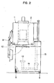
- It further comprises an elevator 11 provided with a plate 12 and capable of entering the bell, by sliding along a guide column 13, in order to transport the load 4 in the tank for the quenching operation .
- Fig. 3 is a partial sectional view of the oven, the bell being shown in the high position to the right of the longitudinal axis of the oven and in the low position to the left of this axis.
- the load rests on support members 14 fixed on reinforcing uprights 15, the support / reinforcement assembly being integral with the bell 2 and extending projecting from the side wall.
- the lower edge 16 of the bell 2 is brought against the upper peripheral part 17 of the tank 3, the bell and the tank then forming a sealed enclosure. The process of obtaining the seal and the mode of release of the charge will be explained later.
- the bell is brought from the high position to the low position and vice versa thanks to two connecting rod / crank devices 18, 18 ′ fixed diametrically opposite one another on the upper part of the oven.
- This device gives the bell a vertical movement, and, at the same time, a rotational movement.
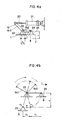
- FIGS. 4a, 4b, 5 and 6 The principle of the mechanism will be described using FIGS. 4a, 4b, 5 and 6.
- a bent lever 19 forming two parts 19.1 and 19.2 and one of whose ends is articulated on the end of a piston 20 actuated by a jack 21.
- the lever is articulated in the bent place, around a shaft 22 mounted on a bearing 23 fixed on the furnace.
- the other end of lever 19, i.e. the part 19.2 is articulated around a shaft 24 mounted on a bearing 25 fixed on the bell 2, this bearing 25 / bell 2 assembly constituting a mobile "hanging" unit.
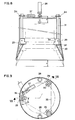
- the bell is placed in the high position, and the load support frame 8, of square shape in the example, rests on the support members 14 (FIG. 6).
- the movement of the bell is shown schematically in fig. 4b.
- the arm pivots around the shaft 22 under the action of the jack, and gives the bell a vertical movement of amplitude H, which, in the example, is of the order of 100 mm, and a rotation of amplitude R1.
- the bell at point A1, is in position lower and its lower edge 16 is already in contact with the upper peripheral part 17 of the container 3.
- the load has accompanied this movement and remains, at this stage, on the support members 14, as shown in FIG. 6.
- the complementary action of the jack on the lever gives the bell a complementary rotation R2, the bell then arriving at point A2.
- the vertical movement in this race is almost zero.
- the section of the basket therefore of the basket support frame 8 is square and four support members 14 are provided. It is clear that it is just as possible to use a basket support frame of round section, the support frame being provided with at least three legs 26, which can come to rest on at least three support members 17 integral bell 2.
- the common characteristic of these two embodiments consists in the fact that the bell is subjected only to a vertical movement of amplitude H. This movement is printed on the bell by means of two jacks 28.
- the support members consist of at least three tabs having a horizontal flat 30 and are free to rotate about a vertical axis, this freedom of rotation being limited to an angle ⁇ , so that the members of load support arranged in the bell 2 consist of at least three tabs 29, each cleat being free to rotate about a vertical axis, this freedom of rotation being limited to an angle ⁇ so that the said cleats can, simultaneously, be brought from an active position to a withdrawal position and vice versa, the axis of each flat being, in the active position, oriented towards the center of the oven and perpendicular to the vertical axis of the latter.
- the simultaneous rotation of the angle cleats each time in the same positive or negative direction is carried out each time by a rod 31 whose lower end pivots in a bore 32 arranged in a support plate 33 fixed to the bell 2 of the furnace and whose upper end emerges from the upper plate of the furnace 1 and is provided with a chain wheel 34, the cleat 29, placed directly above the support plate 33 being integral with the rod 31, and in that the chain wheels are connected together by a chain 35 itself taken in a nut 36 fixed to the end of a jack 37 itself mounted on the upper part of the oven and with an axis parallel to a chain strand 38 connecting two neighboring chain wheels, the actuation of the jack subjecting the chain to a rectilinear movement of amplitude L in one direction or the other, this reciprocating rectilinear movement being transformed, by means of chain wheels, in reciprocating rotary movement of the angle cleats ⁇ .
- the angle ⁇ is equal to 90 °.
- the support members consist of at least three pawls 39 each provided with a horizontal flat 40, the pawls being able to tilt simultaneously around axes which are horizontal and oriented tangentially with respect to the bell, of a active position towards a withdrawal position and vice versa.
- the bell has, at the location of each pawl, a release cage 44, so as to allow the pawl to switch from the active position to the withdrawal position.
- bell furnace and quenching tank which is the subject of the present invention perfectly meets the objectives sought: it allows a tight junction between the bell and the tank and a supply of protective gas.
- the quality of the hardened parts is thus considerably improved, the gas is not dispersed, which saves it.
- any emission of particles or solid or / and liquid and / or gaseous elements into the surrounding atmosphere is avoided. Likewise, any loss of energy is excluded.
Landscapes
- Chemical & Material Sciences (AREA)
- Engineering & Computer Science (AREA)
- Physics & Mathematics (AREA)
- Thermal Sciences (AREA)
- Crystallography & Structural Chemistry (AREA)
- Mechanical Engineering (AREA)
- Materials Engineering (AREA)
- Metallurgy (AREA)
- Organic Chemistry (AREA)
- Solid-Phase Diffusion Into Metallic Material Surfaces (AREA)
- Heat Treatment Of Articles (AREA)
Applications Claiming Priority (2)
| Application Number | Priority Date | Filing Date | Title |
|---|---|---|---|
| CH2145/87 | 1987-06-05 | ||
| CH214587 | 1987-06-05 |
Publications (1)
| Publication Number | Publication Date |
|---|---|
| EP0295207A1 true EP0295207A1 (de) | 1988-12-14 |
Family
ID=4226921
Family Applications (1)
| Application Number | Title | Priority Date | Filing Date |
|---|---|---|---|
| EP88810354A Withdrawn EP0295207A1 (de) | 1987-06-05 | 1988-06-01 | Anordnung für einen Haubenglühofen und Abschreckbad |
Country Status (2)
| Country | Link |
|---|---|
| US (1) | US4858893A (de) |
| EP (1) | EP0295207A1 (de) |
Cited By (1)
| Publication number | Priority date | Publication date | Assignee | Title |
|---|---|---|---|---|
| FR2779217A1 (fr) * | 1998-06-02 | 1999-12-03 | Francois Studer Sa | Installation de traitement thermique |
Families Citing this family (2)
| Publication number | Priority date | Publication date | Assignee | Title |
|---|---|---|---|---|
| WO2007073707A1 (en) * | 2005-12-29 | 2007-07-05 | Lac S.R.O. | Furnace, particularly for thermal and chemotermal treatment of metal products |
| DE102017121830A1 (de) * | 2017-09-20 | 2019-03-21 | Ebner Industrieofenbau Gmbh | Portable Trägervorrichtung für eine Ofencharge und Handhabungssystem für die Trägervorrichtung |
Citations (6)
| Publication number | Priority date | Publication date | Assignee | Title |
|---|---|---|---|---|
| FR676428A (fr) * | 1929-06-10 | 1930-02-22 | Metallgesellschaft Ag | Procédé et dispositif pour le recuit désoxydant des métaux |
| FR1521505A (fr) * | 1967-03-07 | 1968-04-19 | Fours Ripoche | Four à cloche |
| CH478918A (fr) * | 1968-08-26 | 1969-09-30 | Kaesermann & Sperisen S A | Installation automatique pour traiter thermiquement des objets |
| EP0070347A1 (de) * | 1981-07-17 | 1983-01-26 | Michel Spérisen, Equipements industriels | Wärmebehandlungsvorrichtung |
| US4415145A (en) * | 1980-06-16 | 1983-11-15 | Firma Dr. Werner Herdieckerhoff | Metal charge treatment apparatus |
| DE3525635A1 (de) * | 1985-07-18 | 1987-01-22 | Kohnle Wolfgang | Anlage fuer die waermebehandlung von metallteilen |
Family Cites Families (8)
| Publication number | Priority date | Publication date | Assignee | Title |
|---|---|---|---|---|
| US1481338A (en) * | 1922-04-20 | 1924-01-22 | Standard Underground Cable Co Canada | Annealing furnace |
| US1838015A (en) * | 1925-12-01 | 1931-12-22 | Bbc Brown Boveri & Cie | Annealing apparatus |
| US1876960A (en) * | 1929-01-14 | 1932-09-13 | Charles F Kenworthy Inc | Annealing furnace |
| AT167102B (de) * | 1949-06-20 | 1950-11-10 | Elektrowaermebau Ing Josef Ebn | Vorrichtung zum Glühen und Vergüten von Stangen, Profilen und Rohren aus Eisen und Nichteisenmetallen |
| GB899793A (en) * | 1960-03-04 | 1962-06-27 | Ass Elect Ind | Improvements in and relating to furnaces |
| US3381947A (en) * | 1965-09-20 | 1968-05-07 | Midland Ross Corp | Furnace vestibule having a movable ceiling |
| FR95877E (fr) * | 1968-09-30 | 1971-11-12 | Ugine Kuhlmann | Procédé et appareil de traitement de produits métallurgiques en particulier en acier. |
| DE2924270C2 (de) * | 1979-06-15 | 1986-10-16 | Dr. Werner Herdieckerhoff, Nachf. Industrieöfen-Apparatebau, 4750 Unna | Arbeitsverfahren zur Gefüge- und/oder Oberflächenveredelung von Metallen und Vorrichtung dafür |
-
1988
- 1988-05-31 US US07/200,727 patent/US4858893A/en not_active Expired - Fee Related
- 1988-06-01 EP EP88810354A patent/EP0295207A1/de not_active Withdrawn
Patent Citations (6)
| Publication number | Priority date | Publication date | Assignee | Title |
|---|---|---|---|---|
| FR676428A (fr) * | 1929-06-10 | 1930-02-22 | Metallgesellschaft Ag | Procédé et dispositif pour le recuit désoxydant des métaux |
| FR1521505A (fr) * | 1967-03-07 | 1968-04-19 | Fours Ripoche | Four à cloche |
| CH478918A (fr) * | 1968-08-26 | 1969-09-30 | Kaesermann & Sperisen S A | Installation automatique pour traiter thermiquement des objets |
| US4415145A (en) * | 1980-06-16 | 1983-11-15 | Firma Dr. Werner Herdieckerhoff | Metal charge treatment apparatus |
| EP0070347A1 (de) * | 1981-07-17 | 1983-01-26 | Michel Spérisen, Equipements industriels | Wärmebehandlungsvorrichtung |
| DE3525635A1 (de) * | 1985-07-18 | 1987-01-22 | Kohnle Wolfgang | Anlage fuer die waermebehandlung von metallteilen |
Cited By (2)
| Publication number | Priority date | Publication date | Assignee | Title |
|---|---|---|---|---|
| FR2779217A1 (fr) * | 1998-06-02 | 1999-12-03 | Francois Studer Sa | Installation de traitement thermique |
| WO1999063289A1 (fr) * | 1998-06-02 | 1999-12-09 | Studer François S.A. | Installation de traitement thermique |
Also Published As
| Publication number | Publication date |
|---|---|
| US4858893A (en) | 1989-08-22 |
Similar Documents
| Publication | Publication Date | Title |
|---|---|---|
| EP0388333B1 (de) | Vorrichtung zu kontinuierlichen folgenden Vakuumwärmebehandlungen | |
| EP0533615B1 (de) | Wärmebehandlungsanlage für aufeinanderfolgende Chargen | |
| FR2470744A1 (fr) | Dispositif pour le chargement de marchandises en colis sur des palettes | |
| EP0296102B2 (de) | Vorrichtung mit mehreren Einzelteilen für Wärmebehandlungen | |
| EP0295207A1 (de) | Anordnung für einen Haubenglühofen und Abschreckbad | |
| EP0148802B1 (de) | Einrichtung zur Handhabung von Brennstoffelementen und Brennstoffelement für die Vorrichtung | |
| FR2621023A1 (fr) | Installation automatique de traitement thermochimique rapide | |
| EP0785402B1 (de) | Wärmebehandlungsanlage für eine Ladung aus metallischen Stücken | |
| EP0248251B1 (de) | Automatisierte Vorrichtung zum Ausmauern eines Gefässes | |
| EP2143359B1 (de) | Kessel zur Wärmebehandlung | |
| EP1193317B1 (de) | Wärmebehandlungsanlage für Ladungen von metallischen Werkstücken | |
| EP0747493A2 (de) | Wärmebehandlungsanlage | |
| EP0477117B1 (de) | Wandelbare und flexible Anlage zur Wärmebehandlung | |
| CH638298A5 (fr) | Installation de traitement thermique a four cloche mobile. | |
| EP0806485A1 (de) | Wärmebehandlungsanlage | |
| FR2617145A1 (fr) | Magasin de stockage et de distribution d'objets | |
| EP0463913A1 (de) | Automatische Fördervorrichtung für mehrere Positionier- oder Verbindungselemente | |
| FR2658654A1 (fr) | Grappin de levage et de deplacement d'un objet entre une position immergee dans un liquide chaud tel qu'un metal et une position emergee dans un gaz. | |
| EP0973001B1 (de) | Verfahren zum Befestigen und Entfernen von Gut in einem Wärmebehandlungsvorrichtung mit einem bodenlosen Ofen | |
| EP1092121B1 (de) | Wärmebehandlungsanlage | |
| FR2713322A1 (fr) | Four vertical de traitement thermique sous vide. | |
| EP0051241A1 (de) | Verfahren und Vorrichtung zum Handhaben langgestreckter grosser Gegenstände | |
| FR2533541A1 (fr) | Procede et appareil pour decharger un conteneur rempli de piles | |
| CH616452A5 (en) | Quenching process and plant for its use | |
| FR2819481A1 (fr) | Dispositif et procede de transfert d'objets entre deux recipients ouverts |
Legal Events
| Date | Code | Title | Description |
|---|---|---|---|
| PUAI | Public reference made under article 153(3) epc to a published international application that has entered the european phase |
Free format text: ORIGINAL CODE: 0009012 |
|
| AK | Designated contracting states |
Kind code of ref document: A1 Designated state(s): AT BE CH DE ES FR GB IT LI NL SE |
|
| 17P | Request for examination filed |
Effective date: 19890520 |
|
| 17Q | First examination report despatched |
Effective date: 19901218 |
|
| STAA | Information on the status of an ep patent application or granted ep patent |
Free format text: STATUS: THE APPLICATION IS DEEMED TO BE WITHDRAWN |
|
| 18D | Application deemed to be withdrawn |
Effective date: 19930113 |