EP0295237B1 - Dispositif pour l'actionnement d'aiguillage - Google Patents
Dispositif pour l'actionnement d'aiguillage Download PDFInfo
- Publication number
- EP0295237B1 EP0295237B1 EP88890139A EP88890139A EP0295237B1 EP 0295237 B1 EP0295237 B1 EP 0295237B1 EP 88890139 A EP88890139 A EP 88890139A EP 88890139 A EP88890139 A EP 88890139A EP 0295237 B1 EP0295237 B1 EP 0295237B1
- Authority
- EP
- European Patent Office
- Prior art keywords
- tongue rail
- actuating device
- switch actuating
- rail
- joint head
- Prior art date
- Legal status (The legal status is an assumption and is not a legal conclusion. Google has not performed a legal analysis and makes no representation as to the accuracy of the status listed.)
- Expired - Lifetime
Links
- 241000309551 Arthraxon hispidus Species 0.000 claims description 31
- 238000005266 casting Methods 0.000 claims 1
- 238000005242 forging Methods 0.000 claims 1
- 230000000284 resting effect Effects 0.000 claims 1
- 230000003313 weakening effect Effects 0.000 description 5
- 229910001018 Cast iron Inorganic materials 0.000 description 1
- CWYNVVGOOAEACU-UHFFFAOYSA-N Fe2+ Chemical compound [Fe+2] CWYNVVGOOAEACU-UHFFFAOYSA-N 0.000 description 1
- 229910000754 Wrought iron Inorganic materials 0.000 description 1
- 238000010276 construction Methods 0.000 description 1
- 230000035945 sensitivity Effects 0.000 description 1
- 125000006850 spacer group Chemical group 0.000 description 1
Images


Classifications
-
- B—PERFORMING OPERATIONS; TRANSPORTING
- B61—RAILWAYS
- B61L—GUIDING RAILWAY TRAFFIC; ENSURING THE SAFETY OF RAILWAY TRAFFIC
- B61L5/00—Local operating mechanisms for points or track-mounted scotch-blocks; Visible or audible signals; Local operating mechanisms for visible or audible signals
Definitions
- the invention relates to a switch actuating device having a locking clip which can be displaced by a slide rod, the end of which facing the tongue rail has an articulated head to which the tongue rail is pivotally connected, and the other end of which has a locking clip head which cooperates with a locking piece, a shoulder of the Locking clip head rests in the locking position on a shoulder of the locking piece and the tongue rail is articulated on the joint head of the locking clip via a pin arranged in an elongated hole extending in the longitudinal direction of the tongue rail.
- the object of the invention is to simplify the construction in an arrangement described above, to eliminate the risk of breakage of the tongue rail and to enable a more precise articulation and guidance of the locking clip.
- the invention consists essentially in the fact that the elongated hole is arranged in a precisely machined connecting piece rigidly connected to the switch tongue rail. The fact that the elongated hole is provided in a connecting piece prevents a weakening of the rail foot of the switch tongue rail. If this connector is screwed to the switch tongue rail, as it corresponds to a preferred embodiment, the screw holes do not represent a dangerous weakening.
- this switch actuating device can be used both as a first closure for the rail tongue and as can also be used as a second or third closure, for example for the wing rails.
- a connector can be machined more precisely be than the rail foot and therefore the articulation of the connector to the joint head can be done more precisely.
- the connecting piece expediently has a plane-parallel plate in which the elongated hole is arranged, the joint head preferably engaging around the plate on both sides. Such a plane-parallel plate can be machined so precisely that easy movement is ensured with little play between the contact surfaces of the joint head and plate.
- the arrangement is expediently such that the plane-parallel plate having the elongated hole lies approximately in the plane of the foot of the tongue rail.
- the arrangement is such that the joint head has a bracket encompassing the slide rod in the region of its articulation point on the connecting piece.
- the arrangement of such a bracket is facilitated in that the elongated hole is arranged in a connecting piece which protrudes laterally from the foot of the tongue rail and therefore creates enough space for the bracket.
- the locking clip is slidably connected to the slide rod.
- the bracket is expediently formed by a hook-shaped rod welded to the joint head.
- the joint head has a bracket on both sides. This has the advantage that the same locking clip can be used on the right and left.
- the pin by means of which the tongue rail is articulated on the joint head, can be mounted off-center in a sliding block, preferably square, guided in the elongated hole.
- a sliding block preferably square
- the distance between the pivot pin of the joint head and the tongue rail can be adjusted. If this sliding block is square in plan view, there are four adjustment positions and adjustment can therefore be carried out in smaller steps.
- the elongated hole is arranged in a separate connector, which can be machined more precisely than the rail base itself, such fine adjustment levels of the adjustment by means of the square sliding block can be used effectively. If the elongated hole is arranged in a part that is not precisely machined, such as in the rail foot, the sensitivity of the adjustment is not achieved.
- the connector is screwed to the web of the tongue rail.
- This has the advantage that the screw holes in the web of the tongue rail hardly cause a weakening of the tongue rail and there is also the advantage that the spacing of the pivot pin of the joint head can be adjusted by simply inserting spacer plates between the web of the tongue rail and the connecting piece .
- the design according to the invention is expediently made such that the connecting piece is formed by two plates approximately at right angles to one another, which are welded at their ends to side cheeks, one plate having the elongated hole between the side cheeks and the other plate having holes for the connector with the web of the tongue rail connecting screws. In this way, a stable and rigid connecting piece is created and precise guidance of the pivot pin of the joint head in the elongated hole is ensured.
- the closure piece can be screwed onto the outside of the web of the stock rail.
- the closure piece is rigidly fixed in its position, the pin of the joint head being freely displaceable in the elongated hole and can always remain in the same position relative to the closure piece.
- the arrangement is expediently such that the closure piece lies below the rail foot of the stock rail and is screwed onto the web of the stock rail Flange forms a one-piece component, which encompasses the base of the stock rail.
- FIG. 1 and 2 show a cross section through the stock rail and tongue rail and a top view in the open position.
- 3 and 4 show a cross section through the stock rail and tongue rail in the closed state in a somewhat modified embodiment.
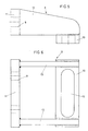
- Fig. 5 and 6 show the connector in side view and top view.
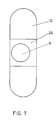
- Fig. 7 shows a sliding block.
- 1 represents the stock rail and 2 the tongue rail.
- 3 is the slide rod and 4 is the locking clip, the joint head 5 of which is articulated to the tongue rail 2 via a pin 6.
- a connector 8 is screwed to the tongue rail web 7, the screw holes being indicated by 9.
- the connector 8, which is shown in Fig. 5 and 6 on a larger scale, has two plane-parallel plates 10 and 11, wherein an elongated hole 12 is provided in the plate 10, in which the pin 6 engages.
- the two plates 10 and 11 are connected to one another by means of welded-on side cheeks 13.
- the joint head 5 has a bracket 14 which engages around the slide rod 3 in a hook-shaped manner and thus connects the joint head 5 to the slide rod.
- the locking clip 4 is thus slidably connected to the slide rod 3.
- the closure piece 15 is the closure piece in which the slide rod 3 and the closure clip 4 are guided.
- the locking clip head 16 of the locking clip 4 lies in a recess 17 of the slide rod 3.
- the locking clip head 16 lies against the mouth 18 of the locking piece 15, so that the tongue rail 2 is in contact with the Stock rail is held.
- the closure piece 15 is combined with a flange 19 which is screwed onto the outside of the stock rail 1 to form a one-piece component 20 which engages around the rail foot 21 of the stock rail.
- FIGS. 3 and 4 differs from the embodiment according to FIGS. 1 and 2 only in that the connecting piece 22 is screwed onto the rail foot 23 of the tongue rail.
- This connector 22 consists of a cranked tab which extends in the plane of the rail foot 23.
- the bracket 14 is arranged on one side of the joint head 5. This bracket 14 is inserted into a hole 24 of the joint head 5 and welded to the joint head 5. The bracket can also be arranged on both sides, so that the same locking clip 4 can be used for right and left locking, as indicated by 14 'in FIG.
- the flanks 25 of the closure clip head 16 are slightly cambered or arcuate in order to reduce the friction in the closure piece 15.
- the pin 6 is guided in the slot 12 by means of a sliding block 26. As FIG. 7 shows, the pin 6 is inserted eccentrically in a square sliding block 26. By turning the sliding block, the distance of the pin 6 from the tongue rail can be adjusted.
- the connector can also consist of cast iron or wrought iron.
Landscapes
- Engineering & Computer Science (AREA)
- Mechanical Engineering (AREA)
- Switches With Compound Operations (AREA)
- Paper (AREA)
- Credit Cards Or The Like (AREA)
- Electrical Discharge Machining, Electrochemical Machining, And Combined Machining (AREA)
- Vehicle Body Suspensions (AREA)
- Push-Button Switches (AREA)
- Control Of Motors That Do Not Use Commutators (AREA)
- Seats For Vehicles (AREA)
- Portable Nailing Machines And Staplers (AREA)
- Switch Cases, Indication, And Locking (AREA)
- Railway Tracks (AREA)
- Power-Operated Mechanisms For Wings (AREA)
- Selective Calling Equipment (AREA)
- Burglar Alarm Systems (AREA)
- Keying Circuit Devices (AREA)
Claims (12)
- Dispositif d'actionnement d'aiguillage avec une pince de fermeture (4) pouvant être déplacée par une tigepoussoir (3), dont l'extrémité orientée vers la lame d'aiguille (2) présente une tête d'articulation (5), avec laquelle la lame d'aiguille (2) est reliée de manière articulée en rotation, et dont l'autre extrémité présente une tête de pince de fermeture (16), qui coopère avec un obturateur (15), un épaulement de la tête de pince de fermeture (16) étant contigu d'un épaulement de l'obturateur (15) dans la position de fermeture et la lame d'aiguille (2) étant articulée sur la tête d'articulation (5) de la pince de fermeture (4) par l'intermédiaire d'un tourillon (6) s'étendant dans un trou allongé (12) qui s'étend dans le sens longitudinal de la lame d'aiguille (2), caractérisé en ce que le trou allongé (12) est disposé dans une pièce de raccordement (8,22) reliée de manière rigide avec la lame d'aiguille et usinée avec précision.
- Dispositif d'actionnement d'aiguillage selon la revendication 1, caractérisé en ce que la pièce de raccordement (8,22) est vissée à la lame d'aiguille (2).
- Dispositif d'actionnement d'aiguillage selon la revendication 1 ou 2, caractérisé en ce que la pièce de raccordement (8,22) présente une plaque à faces planes et parallèles (10), dans laquelle est disposé le trou allongé (12), la tête d'articulation (5) entourant de préférence la plaque (10) des deux côtés.
- Dispositif d'actionnement d'aiguillage selon la revendication 3, caractérisé en ce que la plaque à faces planes et parallèles (10) comprenant le trou allongé (12) se trouve approximativement dans le plan du pied de la lame d'aiguille (2).
- Dispositif d'actionnement d'aiguillage selon l'une quelconque des revendications 1 à 4, caractérisé en ce que la tête d'articulation (5) présente dans le secteur de son point d'articulation sur la pièce de raccordement (8,22) un étrier (14) entourant la tige-poussoir (3).
- Dispositif d'actionnement d'aiguillage selon la revendication 4 ou 5, caractérisé en ce que l'étrier (14) est formé d'une barre recourbée en forme de crochet et soudée à la tête d'articulation.
- Dispositif d'actionnement d'aiguillage selon la revendication 5 ou 6, caractérisé en ce que la tête d'articulation (5) présente un étrier (14,14') des deux côtés.
- Dispositif d'actionnement d'aiguillage selon l'une quelconque des revendications 1 à 7, caractérisé en ce que le tourillon (6), au moyen duquel la lame d'aiguille (2) est articulée sur la tête d'articulation (5), est supporté à l'extérieur et au milieu dans un coussinet de coulisse (26), de préférence carré, introduit dans le trou allongé (12).
- Dispositif d'actionnement d'aiguillage selon l'une quelconque des revendications 1 à 8, caractérisé en ce que la pièce de raccordement (8) est vissée à la barrette de la lame d'aiguille (2).
- Dispositif d'actionnement d'aiguillage selon l'une quelconque des revendications 1 à 9, caractérisé en ce que la pièce de raccordement (8) est formée de deux plaques (10 et 11) formant approximativement entre elles un angle droit, qui sont soudées à leurs extrémités à des cloisons latérales (13), l'une des plaques (10) présentant le trou allongé (12) entre les cloisons latérales (13) et l'autre plaque (11) présentant des trous (9) pour des vis reliant la pièce de raccordement (8) avec la barrette de la lame d'aiguille (2).
- Dispositif d'actionnement d'aiguillage selon l'une quelconque des revendications 1 à 8, caractérisé en ce que la pièce de raccordement (22) est reliée avec le pied de la lame d'aiguille (2), chevauche sur le pied et s'étend approximativement dans le plan du pied.
- Dispositif d'actionnement d'aiguillage selon l'une quelconque des revendications 1 à 11, caractérisé en ce que la pièce de raccordement (8) se compose d'une pièce coulée ou forgée.
Applications Claiming Priority (2)
| Application Number | Priority Date | Filing Date | Title |
|---|---|---|---|
| AT1456/87 | 1987-06-09 | ||
| AT0145687A AT388198B (de) | 1987-06-09 | 1987-06-09 | Weichenbetaetigungsvorrichtung |
Publications (3)
| Publication Number | Publication Date |
|---|---|
| EP0295237A2 EP0295237A2 (fr) | 1988-12-14 |
| EP0295237A3 EP0295237A3 (en) | 1989-09-06 |
| EP0295237B1 true EP0295237B1 (fr) | 1993-01-20 |
Family
ID=3514304
Family Applications (1)
| Application Number | Title | Priority Date | Filing Date |
|---|---|---|---|
| EP88890139A Expired - Lifetime EP0295237B1 (fr) | 1987-06-09 | 1988-06-06 | Dispositif pour l'actionnement d'aiguillage |
Country Status (10)
| Country | Link |
|---|---|
| US (1) | US4860978A (fr) |
| EP (1) | EP0295237B1 (fr) |
| AT (2) | AT388198B (fr) |
| BG (1) | BG48805A3 (fr) |
| DE (1) | DE3877631D1 (fr) |
| DK (1) | DK167247B1 (fr) |
| ES (1) | ES2037879T3 (fr) |
| NO (1) | NO165850C (fr) |
| PL (1) | PL158644B1 (fr) |
| YU (1) | YU47604B (fr) |
Families Citing this family (10)
| Publication number | Priority date | Publication date | Assignee | Title |
|---|---|---|---|---|
| AU593388B2 (en) * | 1986-09-26 | 1990-02-08 | Public Transport Corporation | Railway track switching apparatus |
| DE4014248A1 (de) * | 1990-05-04 | 1991-11-07 | Butzbacher Weichenbau Gmbh | Vorrichtung zum verriegeln einer weichenzunge mit einer backenschiene |
| DE4014249A1 (de) * | 1990-05-04 | 1991-11-07 | Butzbacher Weichenbau Gmbh | Vorrichtung zum verriegeln einer weichenzunge |
| SE506183C2 (sv) * | 1993-05-27 | 1997-11-17 | Abb Daimler Benz Transp | Anordning vid järnvägsspår för omläggning av spårväxel |
| ES2124643B1 (es) * | 1995-01-26 | 1999-10-16 | Instalaciones Alfar Sa De | Nueva disposicion del mecanismo de seguridad en desvios, aplicable en traviesas huecas para lineas ferroviarias polivalentes. |
| DE19732477C2 (de) * | 1997-07-28 | 2001-04-26 | Edmund Muehlhans | Vorrichtung für den Ausgleich von Längsbewegungen von Weichenzungen an Stell-oder Überwachungseinrichtungen |
| AT405808B (de) * | 1997-10-22 | 1999-11-25 | Vae Ag | Anschlusseinrichtung für eine weichenbetätigungseinrichtung und/oder einen verschluss |
| KR100578407B1 (ko) * | 2002-10-29 | 2006-05-11 | 임연희 | 철도분기기용 록킹 및 검지장치 |
| KR100738591B1 (ko) | 2006-10-18 | 2007-07-11 | 삼표이앤씨 주식회사 | 분기기용 잠금장치 |
| US11414108B2 (en) * | 2018-12-10 | 2022-08-16 | L&W Industries, LLC | Railroad switch circuit controller assembly |
Family Cites Families (17)
| Publication number | Priority date | Publication date | Assignee | Title |
|---|---|---|---|---|
| NL6775C (fr) * | 1900-01-01 | |||
| US394943A (en) * | 1888-12-18 | Clip for railroad-switch pivotal tie-rods | ||
| US962698A (en) * | 1909-07-01 | 1910-06-28 | John E Conley | Switch-bar-adjusting device. |
| US951107A (en) * | 1909-10-05 | 1910-03-08 | St Louis Frog & Switch Company | Switch-rod. |
| DE542402C (de) * | 1928-04-01 | 1932-01-23 | Josef Voegele A G | Spitzenverschluss fuer aufschneidbare Weichen |
| US2099559A (en) * | 1934-12-07 | 1937-11-16 | Ramapo Ajax Corp | Railway switch |
| CH196526A (de) * | 1937-06-17 | 1938-03-15 | Carl Eichmann | Zungenangriff für Eisenbahnweichen. |
| US2177148A (en) * | 1937-10-22 | 1939-10-24 | Walter S Newhall | Adjusting device for railroad switch points |
| US2213500A (en) * | 1938-06-04 | 1940-09-03 | James C Mock | Swivel connection for railway switches and the like |
| DE837397C (de) * | 1951-03-04 | 1952-04-28 | Wilhelm Waesche | Spitzenverschluss fuer aufschneidbare Weichen mit Gleitbefestigung der Verriegelungseinrichtungen an den Zungen |
| FR1223768A (fr) * | 1958-05-09 | 1960-06-20 | Stin | Dispositif de calage permettant le talonnage pour aiguilles de voies ferrées |
| AT213941B (de) * | 1959-08-11 | 1961-03-10 | Carl Dan Peddinghaus Kommandit | Klammerspitzenverschluß für Weichenzungen |
| AT250433B (de) * | 1964-09-15 | 1966-11-10 | Oesterr Alpine Montan | Weichenbetätigungsvorrichtung |
| AT314577B (de) * | 1971-09-21 | 1974-04-10 | Oesterr Alpine Montan | Vignolschienenweiche |
| US3836771A (en) * | 1973-01-26 | 1974-09-17 | Berst P | Track switch with latch |
| AT328488B (de) * | 1974-10-15 | 1976-03-25 | Voest Ag | Vignolschienenweiche |
| DE3115943C2 (de) * | 1981-04-22 | 1984-02-02 | Carl Dan. Peddinghaus Gmbh & Co Kg, 5828 Ennepetal | Klammerverschluß für Eisenbahnweichen |
-
1987
- 1987-06-09 AT AT0145687A patent/AT388198B/de not_active IP Right Cessation
-
1988
- 1988-06-06 DE DE8888890139T patent/DE3877631D1/de not_active Expired - Fee Related
- 1988-06-06 AT AT88890139T patent/ATE84755T1/de not_active IP Right Cessation
- 1988-06-06 ES ES198888890139T patent/ES2037879T3/es not_active Expired - Lifetime
- 1988-06-06 EP EP88890139A patent/EP0295237B1/fr not_active Expired - Lifetime
- 1988-06-07 YU YU110388A patent/YU47604B/sh unknown
- 1988-06-07 PL PL1988272897A patent/PL158644B1/pl unknown
- 1988-06-08 DK DK310588A patent/DK167247B1/da not_active IP Right Cessation
- 1988-06-08 NO NO882530A patent/NO165850C/no not_active IP Right Cessation
- 1988-06-09 US US07/204,355 patent/US4860978A/en not_active Expired - Fee Related
- 1988-06-09 BG BG084419A patent/BG48805A3/xx unknown
Also Published As
| Publication number | Publication date |
|---|---|
| US4860978A (en) | 1989-08-29 |
| NO165850B (no) | 1991-01-07 |
| PL272897A1 (en) | 1989-03-06 |
| EP0295237A3 (en) | 1989-09-06 |
| YU110388A (en) | 1991-06-30 |
| YU47604B (sh) | 1995-10-24 |
| NO882530L (no) | 1988-12-12 |
| BG48805A3 (en) | 1991-05-15 |
| DK310588A (da) | 1988-12-10 |
| NO165850C (no) | 1991-04-17 |
| ATA145687A (de) | 1988-10-15 |
| AT388198B (de) | 1989-05-10 |
| DK167247B1 (da) | 1993-09-27 |
| PL158644B1 (en) | 1992-09-30 |
| EP0295237A2 (fr) | 1988-12-14 |
| ES2037879T3 (es) | 1993-07-01 |
| DE3877631D1 (de) | 1993-03-04 |
| DK310588D0 (da) | 1988-06-08 |
| NO882530D0 (no) | 1988-06-08 |
| ATE84755T1 (de) | 1993-02-15 |
Similar Documents
| Publication | Publication Date | Title |
|---|---|---|
| EP0635286B1 (fr) | Planche de glisse | |
| EP0143289A1 (fr) | Coeur pour aiguillages ou croisements et procédé pour la fabrication d'un tel coeur | |
| DE2819162C2 (de) | Personenförderband | |
| DE2807371A1 (de) | Vorrichtung zum verstellen der manschette zur schale eines skischuhs | |
| EP0295237A2 (fr) | Dispositif pour l'actionnement d'aiguillage | |
| DE10240235A1 (de) | Verriegelungsvorrichtung für zwei relativ zueinander verschiebbar gelagerte Bauteile | |
| DE2406646A1 (de) | Skibindungselement | |
| DE69118355T2 (de) | Vorrichtung zur Montage von Schiebetoren | |
| DE2206116B2 (de) | Zugvorrichtung mit zwei gleichzeitig hin- und herbewegbaren Gesperren | |
| DE4313610A1 (de) | Ausstellvorrichtung für einen Dreh-Kipp-Flügel | |
| DE2631173A1 (de) | Armbandverschluss | |
| DE2817768C3 (de) | Geländer oder dergleichen | |
| DE2119499A1 (de) | Kettenanschlußglied | |
| DE3502946C2 (de) | Kettenförderer | |
| DE2748777B2 (de) | Vignolschienenweiche mit einer Herzspitze und verschwenkbar angeordneten Flügelschienen | |
| EP0215221B1 (fr) | Chenille | |
| WO1987000496A1 (fr) | Element d'articulation des deux extremites de la chenille d'un vehicule chenille | |
| DE2654792A1 (de) | Scharnier fuer stumpf aufliegende tuerfluegel, insbesondere moebelscharnier | |
| EP0711632A1 (fr) | Moyens de serrage | |
| EP1110840B1 (fr) | Boítes de verrouillage | |
| DE2030807B2 (de) | Verstellbarer Fahrzeugsitz, insbesondere Kraftfahrzeugsitz | |
| DE19925559C1 (de) | Kette für Spannrahmentrockner | |
| DE4112928C2 (de) | Klammerverschluß für Weichen | |
| DE19732477C2 (de) | Vorrichtung für den Ausgleich von Längsbewegungen von Weichenzungen an Stell-oder Überwachungseinrichtungen | |
| DE2613738A1 (de) | Einrichtung zur verkeilung oder verriegelung beweglicher teile, insbesondere bei eisenbahnstreckengeraeten |
Legal Events
| Date | Code | Title | Description |
|---|---|---|---|
| PUAI | Public reference made under article 153(3) epc to a published international application that has entered the european phase |
Free format text: ORIGINAL CODE: 0009012 |
|
| AK | Designated contracting states |
Kind code of ref document: A2 Designated state(s): AT BE CH DE ES FR GB GR IT LI LU NL SE |
|
| PUAL | Search report despatched |
Free format text: ORIGINAL CODE: 0009013 |
|
| AK | Designated contracting states |
Kind code of ref document: A3 Designated state(s): AT BE CH DE ES FR GB GR IT LI LU NL SE |
|
| 17P | Request for examination filed |
Effective date: 19891006 |
|
| RAP1 | Party data changed (applicant data changed or rights of an application transferred) |
Owner name: VOEST-ALPINE EISENBAHNSYSTEME GESELLSCHAFT M.B.H. |
|
| 17Q | First examination report despatched |
Effective date: 19910725 |
|
| GRAA | (expected) grant |
Free format text: ORIGINAL CODE: 0009210 |
|
| AK | Designated contracting states |
Kind code of ref document: B1 Designated state(s): AT BE CH DE ES FR GB GR IT LI LU NL SE |
|
| REF | Corresponds to: |
Ref document number: 84755 Country of ref document: AT Date of ref document: 19930215 Kind code of ref document: T |
|
| REF | Corresponds to: |
Ref document number: 3877631 Country of ref document: DE Date of ref document: 19930304 |
|
| ITF | It: translation for a ep patent filed | ||
| GBT | Gb: translation of ep patent filed (gb section 77(6)(a)/1977) |
Effective date: 19930310 |
|
| ET | Fr: translation filed | ||
| REG | Reference to a national code |
Ref country code: ES Ref legal event code: FG2A Ref document number: 2037879 Country of ref document: ES Kind code of ref document: T3 |
|
| REG | Reference to a national code |
Ref country code: GR Ref legal event code: FG4A Free format text: 3007557 |
|
| PLBE | No opposition filed within time limit |
Free format text: ORIGINAL CODE: 0009261 |
|
| STAA | Information on the status of an ep patent application or granted ep patent |
Free format text: STATUS: NO OPPOSITION FILED WITHIN TIME LIMIT |
|
| 26N | No opposition filed | ||
| EPTA | Lu: last paid annual fee | ||
| EAL | Se: european patent in force in sweden |
Ref document number: 88890139.4 |
|
| PGFP | Annual fee paid to national office [announced via postgrant information from national office to epo] |
Ref country code: GB Payment date: 19950515 Year of fee payment: 8 Ref country code: CH Payment date: 19950515 Year of fee payment: 8 |
|
| PGFP | Annual fee paid to national office [announced via postgrant information from national office to epo] |
Ref country code: DE Payment date: 19950518 Year of fee payment: 8 |
|
| PGFP | Annual fee paid to national office [announced via postgrant information from national office to epo] |
Ref country code: BE Payment date: 19950522 Year of fee payment: 8 |
|
| PGFP | Annual fee paid to national office [announced via postgrant information from national office to epo] |
Ref country code: FR Payment date: 19950524 Year of fee payment: 8 |
|
| PG25 | Lapsed in a contracting state [announced via postgrant information from national office to epo] |
Ref country code: GB Effective date: 19960606 |
|
| PG25 | Lapsed in a contracting state [announced via postgrant information from national office to epo] |
Ref country code: LI Effective date: 19960630 Ref country code: CH Effective date: 19960630 Ref country code: BE Effective date: 19960630 |
|
| BERE | Be: lapsed |
Owner name: VOEST-ALPINE EISENBAHNSYSTEME G.M.B.H. Effective date: 19960630 |
|
| GBPC | Gb: european patent ceased through non-payment of renewal fee |
Effective date: 19960606 |
|
| REG | Reference to a national code |
Ref country code: CH Ref legal event code: PL |
|
| PG25 | Lapsed in a contracting state [announced via postgrant information from national office to epo] |
Ref country code: FR Effective date: 19970228 |
|
| PG25 | Lapsed in a contracting state [announced via postgrant information from national office to epo] |
Ref country code: DE Effective date: 19970301 |
|
| REG | Reference to a national code |
Ref country code: FR Ref legal event code: ST |
|
| NLT1 | Nl: modifications of names registered in virtue of documents presented to the patent office pursuant to art. 16 a, paragraph 1 |
Owner name: VAE AKTIENGESELLSCHAFT;VOEST-ALPINE EISENBAHNSYSTE |
|
| PGFP | Annual fee paid to national office [announced via postgrant information from national office to epo] |
Ref country code: NL Payment date: 20030530 Year of fee payment: 16 |
|
| PGFP | Annual fee paid to national office [announced via postgrant information from national office to epo] |
Ref country code: SE Payment date: 20030604 Year of fee payment: 16 |
|
| PGFP | Annual fee paid to national office [announced via postgrant information from national office to epo] |
Ref country code: LU Payment date: 20030605 Year of fee payment: 16 |
|
| PGFP | Annual fee paid to national office [announced via postgrant information from national office to epo] |
Ref country code: ES Payment date: 20030616 Year of fee payment: 16 |
|
| PG25 | Lapsed in a contracting state [announced via postgrant information from national office to epo] |
Ref country code: LU Free format text: LAPSE BECAUSE OF NON-PAYMENT OF DUE FEES Effective date: 20040606 |
|
| PG25 | Lapsed in a contracting state [announced via postgrant information from national office to epo] |
Ref country code: SE Free format text: LAPSE BECAUSE OF NON-PAYMENT OF DUE FEES Effective date: 20040607 Ref country code: ES Free format text: LAPSE BECAUSE OF NON-PAYMENT OF DUE FEES Effective date: 20040607 |
|
| PG25 | Lapsed in a contracting state [announced via postgrant information from national office to epo] |
Ref country code: NL Free format text: LAPSE BECAUSE OF NON-PAYMENT OF DUE FEES Effective date: 20050101 |
|
| EUG | Se: european patent has lapsed | ||
| EUG | Se: european patent has lapsed | ||
| NLV4 | Nl: lapsed or anulled due to non-payment of the annual fee |
Effective date: 20050101 |
|
| PG25 | Lapsed in a contracting state [announced via postgrant information from national office to epo] |
Ref country code: IT Free format text: LAPSE BECAUSE OF NON-PAYMENT OF DUE FEES;WARNING: LAPSES OF ITALIAN PATENTS WITH EFFECTIVE DATE BEFORE 2007 MAY HAVE OCCURRED AT ANY TIME BEFORE 2007. THE CORRECT EFFECTIVE DATE MAY BE DIFFERENT FROM THE ONE RECORDED. Effective date: 20050606 |
|
| REG | Reference to a national code |
Ref country code: ES Ref legal event code: FD2A Effective date: 20040607 |
|
| PGFP | Annual fee paid to national office [announced via postgrant information from national office to epo] |
Ref country code: AT Payment date: 20060616 Year of fee payment: 19 |
|
| PGFP | Annual fee paid to national office [announced via postgrant information from national office to epo] |
Ref country code: GR Payment date: 20060621 Year of fee payment: 19 |
|
| PG25 | Lapsed in a contracting state [announced via postgrant information from national office to epo] |
Ref country code: AT Free format text: LAPSE BECAUSE OF NON-PAYMENT OF DUE FEES Effective date: 20070606 |
|
| PG25 | Lapsed in a contracting state [announced via postgrant information from national office to epo] |
Ref country code: GR Free format text: LAPSE BECAUSE OF NON-PAYMENT OF DUE FEES Effective date: 20080104 |