EP0295394A1 - Méthode et dispositif de formation d'une réserve de fil - Google Patents
Méthode et dispositif de formation d'une réserve de fil Download PDFInfo
- Publication number
- EP0295394A1 EP0295394A1 EP88106465A EP88106465A EP0295394A1 EP 0295394 A1 EP0295394 A1 EP 0295394A1 EP 88106465 A EP88106465 A EP 88106465A EP 88106465 A EP88106465 A EP 88106465A EP 0295394 A1 EP0295394 A1 EP 0295394A1
- Authority
- EP
- European Patent Office
- Prior art keywords
- sleeve
- thread
- winding
- reserve
- tube
- Prior art date
- Legal status (The legal status is an assumption and is not a legal conclusion. Google has not performed a legal analysis and makes no representation as to the accuracy of the status listed.)
- Granted
Links
- 238000004804 winding Methods 0.000 title claims abstract description 88
- 238000000034 method Methods 0.000 title claims description 8
- 230000015572 biosynthetic process Effects 0.000 claims description 6
- 235000013351 cheese Nutrition 0.000 claims description 6
- 238000004519 manufacturing process Methods 0.000 claims description 6
- 238000005520 cutting process Methods 0.000 claims description 3
- 238000000151 deposition Methods 0.000 claims description 2
- 238000012546 transfer Methods 0.000 claims description 2
- 230000000284 resting effect Effects 0.000 claims 1
- 238000011161 development Methods 0.000 description 9
- 210000002435 tendon Anatomy 0.000 description 4
- 230000006835 compression Effects 0.000 description 2
- 238000007906 compression Methods 0.000 description 2
- 241000196324 Embryophyta Species 0.000 description 1
- 241000209035 Ilex Species 0.000 description 1
- 238000013459 approach Methods 0.000 description 1
- 239000011324 bead Substances 0.000 description 1
- 238000007664 blowing Methods 0.000 description 1
- 230000008878 coupling Effects 0.000 description 1
- 238000010168 coupling process Methods 0.000 description 1
- 238000005859 coupling reaction Methods 0.000 description 1
- 230000007547 defect Effects 0.000 description 1
- 239000004744 fabric Substances 0.000 description 1
- 238000012545 processing Methods 0.000 description 1
Images


Classifications
-
- B—PERFORMING OPERATIONS; TRANSPORTING
- B65—CONVEYING; PACKING; STORING; HANDLING THIN OR FILAMENTARY MATERIAL
- B65H—HANDLING THIN OR FILAMENTARY MATERIAL, e.g. SHEETS, WEBS, CABLES
- B65H54/00—Winding, coiling, or depositing filamentary material
- B65H54/02—Winding and traversing material on to reels, bobbins, tubes, or like package cores or formers
- B65H54/28—Traversing devices; Package-shaping arrangements
- B65H54/34—Traversing devices; Package-shaping arrangements for laying subsidiary winding, e.g. transfer tails
-
- B—PERFORMING OPERATIONS; TRANSPORTING
- B65—CONVEYING; PACKING; STORING; HANDLING THIN OR FILAMENTARY MATERIAL
- B65H—HANDLING THIN OR FILAMENTARY MATERIAL, e.g. SHEETS, WEBS, CABLES
- B65H2511/00—Dimensions; Position; Numbers; Identification; Occurrences
- B65H2511/30—Numbers, e.g. of windings or rotations
-
- B—PERFORMING OPERATIONS; TRANSPORTING
- B65—CONVEYING; PACKING; STORING; HANDLING THIN OR FILAMENTARY MATERIAL
- B65H—HANDLING THIN OR FILAMENTARY MATERIAL, e.g. SHEETS, WEBS, CABLES
- B65H2701/00—Handled material; Storage means
- B65H2701/30—Handled filamentary material
- B65H2701/31—Textiles threads or artificial strands of filaments
Definitions
- the invention relates to a thread reserve on the sleeve end of a cross-wound bobbin, consisting of a plurality of turns crossing and holding the thread end, not belonging to the cross-wound bobbin, and a method and device for producing the thread reserve.
- the thread tendon can be spooled at both ends by reserve windings and the later cross-wound bobbin can cover the reserve windings in such a way that it is no longer visible to which side of the thread string the reserve thread is connected. For this reason, when trying to pull off the thread reserve, the reserve thread or the tendon is often torn off, with the result that the thread reserve can no longer be released.
- the thread reserve is more or less difficult to release later, even if no special occurrences are observed in the reserve formation and when winding the package.
- the invention has for its object to form a thread reserve that can be easily released again, the thread end is easy to find and that can be easily and easily produced in a reproducible quality with simple means.
- this object is achieved in that, in the case of a generic thread reserve, the thread end lies on the sleeve end in a straight line or, depending on the type of sleeve, along a helix or along a spatial spiral with a comparatively large slope and is preferably wound over in one layer without tendon formation with a predeterminable number of cross-wise adjacent turns that the turns are preferably arranged next to one another at a distance and that the first turn, which spins the thread end, is furthest from the sleeve edge.
- the thread end is only wound on one side and not on both sides.
- the difficulties that regularly occur with spooled string tendons are therefore eliminated.
- the turns do not cross each other, so that later the thread reserve from the end without difficulty and without impermissibly high thread tensions and the associated danger of damage can be resolved.
- the thread is drawn out from under the turns, the turns dissolving one after the other and the last turn still holding the reserve thread.
- the end section of the thread end protrudes a maximum of 1 cm below the winding turns of the thread reserve.
- the thread end now only slightly protruding from the sleeve edge can no longer be easily destroyed, squeezed or damaged. It is generally no longer squeezed between the edge of the sleeve and the sleeve plate during later clamping operations because of its brevity.
- the end section of the thread end is guided around the sleeve edge and deposited in the interior of the sleeve in a length of at least a few centimeters.
- the end of the thread is then safely picked up and can be easily removed automatically later using suction or blowing air.
- suction or blowing air there is still the risk of squeezing between the edge of the tube and the tube plate, but this creates a new thread end that is still easy to find and the resulting piece of residual thread is still safely deposited in the interior of the tube and cannot be wound in so easily.
- a method for producing a thread reserve on the sleeve end of a package consisting of a plurality of turns which cross and hold the thread end and are not part of the package winding is characterized in that the thread connected to a payout spool has a length of at least a few centimeters in a central, arranged in a rotatable sleeve plate suction tube, then clamped a sleeve between these and another rotatable sleeve plate and thereby the thread between the sleeve plate and sleeve edge is held that the thread from The edge of the tube is guided out to the starting point of the first turn of the thread reserve and the sleeve is then rotated at the latest so that the thread is returned in a predetermined number of turns in the direction of the edge of the tube in such a way that the turns do not cross each other, whereupon either the Rotation of the tube is brought to a standstill, the tube is unclamped and
- the central suction tube which can for example be arranged stationary in the center of the sleeve plate, prevents the string from forming chords and the disadvantages associated therewith.
- the application of initial turns of the cross-wound bobbin prevents the thread reserve from being unintentionally redissolved.
- the thread is advantageously cut between the suction tube and the edge of the sleeve, thereby forming an end section of the thread end which is a maximum of 1 cm long and protrudes under the winding windings of the thread reserve.
- a device for producing a thread reserve on the sleeve end of a cross-wound bobbin, consisting of several turns crossing and holding the thread end, not belonging to the cross-wound bobbin winding for carrying out the method according to one of claims 1 to 6, characterized in that for producing a thread reserve, in which the thread end lying in a straight line or, depending on the type of tube, along a helix or along a spatial spiral of relatively high pitch on the tube end with a predeterminable number of turns lying next to one another without crossing, that the turns are preferably arranged next to one another at a distance and the first spooled Winding furthest from the sleeve edge is that the device has a special winding device that is not identical to the winding device of a winding unit that winds up the cross-wound bobbin, that the winding device is a drive device ng for the sleeve has that the drive device has two rotatably mounted sle
- the drive device can, for example, be designed so that it drives one of the two sleeve plates. But it can also be designed so that it drives the sleeve itself with a friction wheel.
- the winding device for producing an end section of the thread end that protrudes a maximum of 1 cm below the winding windings of the thread reserve has a separating device that operates in the vicinity of the sleeve edge for cutting excess thread length.
- one of the two rotatable sleeve plates has a central suction pipe connected to a suction air source and provided with a suction opening directed towards the inside of the sleeve for sucking in a thread connected to the take-off spool of a winding unit, from which after suction and after clamping the sleeve between the core plate creates the thread reserve.
- an injector can serve as the source of suction air.
- the two rotatably mounted sleeve plates for depositing the end section of the thread end in the interior of the sleeve have air passage bores.
- the suction pipe has a valve which can be optionally set to the shut-off position of the suction air source and to a compressed air source. By placing the valve out of the shut-off position on suction, a thread end coming from a payout spool can be sucked into the suction pipe.
- the valve can be set to bubbles and the length of thread drawn in can be blown into the interior of the sleeve.
- the device is part of a mobile operating device which can be moved from winding station to winding station of a cross-wound bobbin and cooperates with its sleeve gripping device insofar as the sleeve gripping device is a removes empty tube from a tube magazine and presents it to the tube plates of the winding device, releases the tube during the formation of the thread reserve, then detects it again and presents it to a tube receiving device of a winding unit of the machine producing the bobbin.
- the sleeve magazine is located either on the winding unit or on the mobile operating device.
- the operating device is expediently designed as a bobbin changing device.
- the winding unit 1 shows the winding unit 1 of a machine producing cross-wound bobbins. It is an automatic winder which has a plurality of identical winding units which are to be one behind the other in the viewing direction.
- the machine frame 2 of the winding unit 1 carries, among other things, a grooved drum 3 for driving the cheese to be produced and as a tube take-up device a pivotable coil frame 4, which holds the sleeve clamped between rotatable sleeve plates 5, on which the cross-wound bobbin is later to be wound up.
- Fig. 1 shows that the coil frame 4 is pivoted up and has not yet received a sleeve.
- a sleeve 6 is located in the area of a mobile operating device 9, two further sleeves 7 and 8 are still in a sleeve magazine 10 of the winding unit 1. These are conical sleeves for winding conical cross-wound bobbins.
- the sleeve magazine 10 has two runners 11 and 12 on which the sleeves rest. To the outside, the runners 11 and 12 are delimited by side walls 13 and 14.
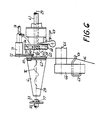
- the operating device 9 is an automatic cross-wound bobbin changer. It has the task of removing a fully wound cross-wound bobbin from the bobbin frame 4 and in its place to provide a bobbin with a thread reserve 15 (FIG. 6), for example the bobbin 6, the bobbin frame 4, which then clamps the bobbin between its bobbin plates 5 and brings against the rotatable grooved drum 3 to the plant.
- the thread reserve 15 is formed from the thread 16 (FIG.
- the operating device 9 has, among other things, a sleeve gripping device, designated overall by 17.
- the sleeve gripping device 17 has an arm 19 which can be pivoted about the pivot axis 18 and on which a cop 21 which is rotatable about the axis of rotation 20 is mounted.
- a pawl 22 is able to hold the head 21 in defined positions with the aid of catches 23. Otherwise, the head can be turned counterclockwise.
- two counter-rotating shafts 24, 25 are fastened, which carry fingers 26, 27, 28, which can grip and hold a sleeve.
- Fig. 1 shows that the fingers 26 to 28 of the sleeve gripping device 17 have removed the sleeve 6 from the sleeve magazine 10 and have brought the longitudinal axis 29 of the sleeve with the longitudinal axis 29 of a special winding device 30 (Fig. 2, Fig. 3) to coincide.
- Fig. 3 indicates that the housing 9 ', 9 ⁇ of the operating device 9 is portal-like, which is to indicate the dash-dotted line 31. Because of the large portal height, it is not possible to show the entire portal in FIG. 3.
- the operating device 9 can be moved on rails in a known manner. Rails and chassis are at the top outside of the drawing level.
- FIG. 3 shows that the winding device 30 has a drive device for the sleeve 6, denoted overall by 32.
- the drive device 32 has two rotatably mounted sleeve plates 33 and 34, both of which are longitudinally displaceable for the purpose of receiving and releasing the sleeve 6.
- the sleeve plate 33 has an air passage bore 77 leading into the open. It is seated at the end of a shaft 35 which, according to FIG. 5, is connected to a sleeve drive element 36.
- the sleeve drive element 36 has the shape of an electric geared motor.
- the shaft 35 is supported in a longitudinally displaceable sleeve 38 by means of roller bearings 37.
- the sleeve 38 is loaded by a compression spring 39 in the clamping direction of the sleeves 6 and slidably mounted in the housing part 9 ⁇ of the operating device 9.
- the sleeve plate 34 has a central air passage bore 78 and therein a central suction pipe 43.
- the suction pipe 43 is connected to a controllable valve 80 by a line, which can be flexible, for example.
- the valve 80 can optionally in the shut-off position and out of the shut-off position either on a suction air source 41 or on a compressed air source 79. If the valve 80 is placed on the suction air source 41, the suction pipe 43 is used to suck in the thread connected to a take-off spool of the winding unit 1.
- the suction pipe 43 is slidably mounted in the direction of the double arrow 44 in the housing part 9 'and with a provided against the sleeve interior suction opening 42.
- the valve 80 is placed on the compressed air source 79.
- the suction pipe 43 carries a rotatable sleeve receiving device 47 by means of two roller bearings 45, 46.
- the sleeve receiving device 47 is connected on the left side to the sleeve plate 34 and a toothed collar 48 which overlaps the sleeve plate.
- the sleeve receiving device 47 is designed as a pinion 49, which engages in a gear wheel 50 of a gear train designated 53 as a whole.
- the gear train 53 belongs to a total of 54 winding counting devices.
- the winding counting device 54 has a pulse sensor 55 which can be set to count a preselected number of pulses. The number of pulses is in proportion to the desired number of turns of the thread reserve.
- the sleeve drive element 36 can be controlled by the pulse sensor 55.
- the pulse sensor 55 begins to count. He switches off the sleeve drive element 36 as soon as he has counted the preselected number of pulses.
- the winding counting device 54 also includes a pulse disk 58 provided with a magnet 57, which is connected to a further gear wheel 51 of the gear train 53.
- the device 9 also has an automatic thread guide, which is denoted overall by 59.
- the automatic thread guide has a guide element 63 leading the thread 16 according to FIG. 5 from the sleeve edge 61 to the starting point of the first turn 62.
- the guide element 63 consists of a guide wire provided with a bead 64, which is seated on a lever 66 which can be pivoted about the pivot axis 65.
- the automatic thread guide 59 also includes a feed device 67, consisting of a hook which is pivotally mounted on a rod 68 and can be pivoted by a pull rod 69.
- the feed device 67 guides the thread 16 from the starting point of the first winding 62 from winding next to winding in the direction of the sleeve edge 61 and over the thread end 70.
- the device 9 also has a separating device 71 for cutting excess thread length.
- the separating device 71 has two separating knives 72, 73 which can be pivoted relative to one another and which can be controlled or operated in a scissor-like manner by means of a shaft 74 via a gear train which is present in the separating device 71 and is not shown here.
- the excess thread length 70 is cut when the separating device 71 is actuated and sucked into the suction pipe 43.
- the thread reserve is formed on the sleeve end 60 of the sleeve 6 (FIG. 3), for example, in the following way:
- the operating device 9 here the cross-wound bobbin changing device, approaches the winding unit 1 and engages at the winding unit. It doesn't lift through here means shown on the coil frame 4, removes the clamped cheese and ensures that the coil frame 4 remains lifted from the slot drum 3, as shown in FIG. 1.
- the arm 19 of the sleeve gripping device 17 pivots clockwise about the pivot axis 18, whereupon the head 21 is rotated counterclockwise. Then the arm 19 pivots back into the position shown in FIG. 1.
- the shafts 24 and 25 By turning the shafts 24 and 25 in opposite directions, the fingers 26 to 28 are opened and brought up from above and below to the sleeve lying in the foremost position in the sleeve magazine 10. The fingers grip the sleeve, for example the sleeve 6 shown in FIG. 1, and align it with the longitudinal axis 29, as shown in FIG. 1.
- the valve 80 is placed on the suction air source 41.
- the thread 16 originating from the payout spool is now presented to the suction opening 42 of the suction pipe 43 by suitable means. It is sucked into the suction pipe 43 and held there, as shown in FIG. 3.
- the separating device 71 is open, the automatic thread guide 59 is still inoperative.
- the suction pipe 43 is moved in the direction of the double arrow 44 to the left, so that the sleeve plate 34 lies against the right sleeve edge 61.
- the thread 16 is clamped between the sleeve edge 61 and the sleeve plate 34 and held.
- the fingers 26 to 28 of the sleeve gripping device 17 still hold the sleeve 6 firmly.
- the automatic thread guide 59 then comes into operation.
- the lever 66 pivots clockwise according to FIG. 2 about the pivot axis 65, so that the guide element detects the thread 16 and guides it towards the starting point of the first turn 62, as shown in FIG. 5 implies.
- the feed device 67 is brought into the starting position, which is also shown in FIG. 5. 4
- the thread 16 now follows a path that is prescribed by the guide element 63 and the feed device 67.
- the fingers 26 to 28 detach from the sleeve 6 after the sleeve 6 is clamped between the sleeve plates 33 and 34.
- the toothed collar 48 guides the thread end over the sleeve edge 61.
- the sleeve drive element 36 can now be switched on to form the thread reserve.
- the gear 43 of the winding counting device 54 runs and at the same time the pull rod 69 of the feed device 67 moves in a controlled manner to the right, so that the thread 16 turns next to the winding from left to right the right sleeve end 60 is wound up.
- FIG. 6 shows the finished thread reserve 15 with only a few turns that spill out the thread end 70 for illustrative reasons.
- the pulse sensor 55 switches the sleeve drive element 36 off again, so that the sleeve 6 comes to a standstill at the moment.
- the pulse sensor 55 also sends a pulse to the automatic control system of the operating device 9, which is not shown here.
- a cam disk package of a control device then starts, which is not shown in more detail here. This cam disk package now controls the following processes:
- the fingers 26 to 28 rest against the sleeve 6, then the suction pipe 43 is pulled back to the right, so that the sleeve 6 is released again from the sleeve plates 33 and 34, as shown in FIG. 6. Then the separator 71 is operated to cut off the excess thread length 70 'and leave only a desired, short thread end 70. In the meantime, the feed device 67 is pivoted back completely by the pull rod 69 and is thus rendered inoperative. The guide element 63 can now also be brought out of contact with the thread 16.
- the thread reserve 62 is now formed.
- the aforementioned cam disk package now controls the sleeve gripping device 17 as follows:
- the arm 19 is rotated clockwise about the pivot axis 18 by a certain angle, so that the longitudinal axis 29 of the sleeve 6 comes into line with the winding axis 75 of the coil frame 4.
- the sleeve 6, which is already provided with a thread reserve gets between the sleeve plates 5 of the bobbin frame 4, which then closes and clamps the sleeve 6.
- the coil frame 4 is now lowered so that the sleeve 6 makes contact with the rotatable grooved drum 3 so that the winding operation can begin.
- the fingers 26 to 28 detach from the sleeve 6 and the arm 19 swings back into the position shown in FIG. 1.
- the operating device 9 has now done its job. It detaches from the winding unit 1 and, if necessary, continues to another winding unit. to work there.
- the separating device 71 can alternatively remain inoperative.
- the pulse sensor 55 can switch the valve 80 to the compressed air source 79 when the sleeve drive element 36 is switched off, as a result of which the end section 76 (FIG. 6) of the thread end is guided around the sleeve edge 61 and deposited in the sleeve 6.
Landscapes
- Replacing, Conveying, And Pick-Finding For Filamentary Materials (AREA)
- Winding Filamentary Materials (AREA)
- Filamentary Materials, Packages, And Safety Devices Therefor (AREA)
Applications Claiming Priority (4)
| Application Number | Priority Date | Filing Date | Title |
|---|---|---|---|
| DE3720220 | 1987-06-17 | ||
| DE3720220 | 1987-06-17 | ||
| DE19873733353 DE3733353A1 (de) | 1987-06-17 | 1987-10-02 | Fadenreserve und verfahren und vorrichtung zum herstellen der fadenreserve |
| DE3733353 | 1987-10-02 |
Publications (2)
| Publication Number | Publication Date |
|---|---|
| EP0295394A1 true EP0295394A1 (fr) | 1988-12-21 |
| EP0295394B1 EP0295394B1 (fr) | 1991-09-04 |
Family
ID=25856736
Family Applications (1)
| Application Number | Title | Priority Date | Filing Date |
|---|---|---|---|
| EP88106465A Expired - Lifetime EP0295394B1 (fr) | 1987-06-17 | 1988-04-22 | Méthode et dispositif de formation d'une réserve de fil |
Country Status (4)
| Country | Link |
|---|---|
| US (1) | US4878629A (fr) |
| EP (1) | EP0295394B1 (fr) |
| JP (1) | JP2637169B2 (fr) |
| DE (2) | DE3733353A1 (fr) |
Families Citing this family (10)
| Publication number | Priority date | Publication date | Assignee | Title |
|---|---|---|---|---|
| DE3911505C2 (de) * | 1989-04-08 | 1999-10-14 | Schlafhorst & Co W | Verfahren und Spulstelle zum Herstellen einer fehlerfreien Kreuzspule |
| US5270526A (en) * | 1989-11-02 | 1993-12-14 | Nippon Conlux Co., Ltd. | Card type recording medium and method of preventing a false use thereof |
| JPH0776981B2 (ja) * | 1989-11-02 | 1995-08-16 | 株式会社日本コンラックス | カード型記録媒体の記録再生装置及びその不正使用防止方法 |
| DE4034482C2 (de) * | 1990-10-30 | 1999-03-11 | Palitex Project Co Gmbh | Verfahren und Vorrichtung zur Fadenzuführung an einer Fadenaufspuleinrichtung einer Textilmaschine |
| DE4211749A1 (de) * | 1992-04-08 | 1993-10-14 | Schlafhorst & Co W | Verfahren und Vorrichtung zum Wickeln einer Fadenreserve |
| DE4241992A1 (de) * | 1992-12-12 | 1994-06-16 | Schlafhorst & Co W | Verfahren und Vorrichtung zum Ansaugen eines Fadenanfangs einer Ablaufspule |
| DE9310332U1 (de) * | 1993-07-12 | 1993-09-02 | W. Schlafhorst AG & Co, 41061 Mönchengladbach | Vorrichtung zum automatischen Wickeln einer Fadenreserve |
| DE19928286A1 (de) * | 1999-06-22 | 2000-12-28 | Schlafhorst & Co W | Automatische Kreuzspulmaschine mit einem verfahrbaren Kreuzspulenwechsler |
| JP4059206B2 (ja) * | 2004-02-06 | 2008-03-12 | 村田機械株式会社 | バンチ巻装置を備えた紡績機 |
| CN111003586A (zh) * | 2019-11-28 | 2020-04-14 | 国网山东省电力公司经济技术研究院 | 输电线缠绕装置 |
Citations (5)
| Publication number | Priority date | Publication date | Assignee | Title |
|---|---|---|---|---|
| DE2503299A1 (de) * | 1975-01-28 | 1976-07-29 | Schuster & Co F M N | Verfahren und vorrichtung zur steuerung einer reservewicklung beim aufspulen eines fadens auf einer spulenhuelse |
| DE2622300A1 (de) * | 1975-05-27 | 1976-12-09 | Vyzk Ustav Pletarsky | Verfahren zum festhalten der auf der spulenkante beim spulen auf einer spulmaschine, insbesondere auf einer automatischen kreuzspulmaschine gebildeten fadenreserve und vorrichtung zum durchfuehren dieses verfahrens |
| DE2330961B2 (de) * | 1973-06-18 | 1979-09-13 | Hoechst Ag, 6000 Frankfurt | Vorrichtung zur Bildung einer Fadenreserve auf einer Aufwickelspule mit wilder Wicklung an schnellaufenden Spulmaschinen |
| DE2936392B1 (de) * | 1979-09-08 | 1980-10-16 | Palitex Project Co Gmbh | Spulenhalter |
| DE3344645A1 (de) * | 1983-12-09 | 1985-06-20 | Schubert & Salzer Maschinenfabrik Ag, 8070 Ingolstadt | Vorrichtung zum bilden einer fadenreservewicklung |
Family Cites Families (14)
| Publication number | Priority date | Publication date | Assignee | Title |
|---|---|---|---|---|
| US1477162A (en) * | 1920-04-14 | 1923-12-11 | Andrew Thomas | Yarn package |
| US2429330A (en) * | 1944-01-19 | 1947-10-21 | American Viscose Corp | Flyer twisting machine |
| FR2158762A5 (fr) * | 1971-10-29 | 1973-06-15 | Rhodiaceta | |
| US3823884A (en) * | 1972-10-16 | 1974-07-16 | Rhone Poulenc Textile | Apparatus and method for forming a piecing end for wound yarn |
| DE2445182C2 (de) * | 1974-09-21 | 1986-06-12 | W. Schlafhorst & Co, 4050 Mönchengladbach | Verfahren und Vorrichtung zum Auswechseln einer fertiggewickelten Kreuzspule gegen eine leere Spulenhülse |
| IT1050679B (it) * | 1974-10-04 | 1981-03-20 | Rieter Ag Maschf | Dispositivo bobinatore con sostituzione automatica di tubetti |
| IT1025197B (it) * | 1974-10-25 | 1978-08-10 | Snia Viscosa | Metodo e dispositivo per il fissag gio terminale della coda die trasferimento di bobine di filati avvolte su stiro trcitoi e similari apparecchiature tessili |
| DE2506930C2 (de) * | 1975-02-19 | 1987-01-29 | W. Schlafhorst & Co, 4050 Mönchengladbach | Verfahren und Vorrichtung zum Bilden einer Fadenreserve aus dem Fadenende einer Textilspule |
| DE2543986B2 (de) * | 1975-10-02 | 1978-06-01 | Schubert & Salzer Maschinenfabrik Ag, 8070 Ingolstadt | Verfahren und Vorrichtung zur Bildung einer Reservewicklung auf einer Spulenhülse |
| GB2140046B (en) * | 1983-05-20 | 1988-03-23 | Rieter Ag Maschf | Bobbin inserting device |
| JPS60112570A (ja) * | 1983-11-18 | 1985-06-19 | Toray Ind Inc | 糸条パツケ−ジの製造方法 |
| JPS60112569A (ja) * | 1983-11-18 | 1985-06-19 | Toray Ind Inc | 糸条パツケ−ジのテ−ル形成方法 |
| US4641793A (en) * | 1985-04-16 | 1987-02-10 | Rieter Machine Works Limited | Thread winding machine and method of performing automatic changeover of winding of a thread |
| DE3607342A1 (de) * | 1986-03-06 | 1987-09-10 | Schuster & Co F M N | Vorrichtung zum bilden einer fadenreserve beim anspulen eines fadens auf einer spulenhuelse |
-
1987
- 1987-10-02 DE DE19873733353 patent/DE3733353A1/de not_active Ceased
-
1988
- 1988-04-22 EP EP88106465A patent/EP0295394B1/fr not_active Expired - Lifetime
- 1988-04-22 DE DE8888106465T patent/DE3864594D1/de not_active Expired - Fee Related
- 1988-06-15 JP JP63145984A patent/JP2637169B2/ja not_active Expired - Lifetime
- 1988-06-16 US US07/208,145 patent/US4878629A/en not_active Expired - Lifetime
Patent Citations (5)
| Publication number | Priority date | Publication date | Assignee | Title |
|---|---|---|---|---|
| DE2330961B2 (de) * | 1973-06-18 | 1979-09-13 | Hoechst Ag, 6000 Frankfurt | Vorrichtung zur Bildung einer Fadenreserve auf einer Aufwickelspule mit wilder Wicklung an schnellaufenden Spulmaschinen |
| DE2503299A1 (de) * | 1975-01-28 | 1976-07-29 | Schuster & Co F M N | Verfahren und vorrichtung zur steuerung einer reservewicklung beim aufspulen eines fadens auf einer spulenhuelse |
| DE2622300A1 (de) * | 1975-05-27 | 1976-12-09 | Vyzk Ustav Pletarsky | Verfahren zum festhalten der auf der spulenkante beim spulen auf einer spulmaschine, insbesondere auf einer automatischen kreuzspulmaschine gebildeten fadenreserve und vorrichtung zum durchfuehren dieses verfahrens |
| DE2936392B1 (de) * | 1979-09-08 | 1980-10-16 | Palitex Project Co Gmbh | Spulenhalter |
| DE3344645A1 (de) * | 1983-12-09 | 1985-06-20 | Schubert & Salzer Maschinenfabrik Ag, 8070 Ingolstadt | Vorrichtung zum bilden einer fadenreservewicklung |
Also Published As
| Publication number | Publication date |
|---|---|
| DE3864594D1 (de) | 1991-10-10 |
| JP2637169B2 (ja) | 1997-08-06 |
| DE3733353A1 (de) | 1988-12-29 |
| EP0295394B1 (fr) | 1991-09-04 |
| JPS6417774A (en) | 1989-01-20 |
| US4878629A (en) | 1989-11-07 |
Similar Documents
| Publication | Publication Date | Title |
|---|---|---|
| DE3802900C2 (fr) | ||
| DE3710692C2 (fr) | ||
| EP2657380B1 (fr) | Procédé et dispositif de fonctionnement de postes de travail d'un métier à tisser à rotor à extrémité ouverte | |
| EP3891089B1 (fr) | Dispositif et procédé d'enroulement d'un fil | |
| EP0367253B1 (fr) | Système d'échange pour un dispositif de mise en place d'un fil dans une machine à bobiner | |
| DE3348199C2 (fr) | ||
| DE3602574C2 (de) | Kreuzspulen herstellende Maschine mit Vorrichtung zur Bildung einer Fadenendreserve auf einer fertig gewickelten Spule | |
| DE19533833A1 (de) | Kreuzspulenwechseleinrichtung einer Kreuzspulen herstellenden Textilmaschine | |
| DE3339670A1 (de) | Verfahren und vorrichtung zum steuern und wiederaufnehmen des abgeschnittenen fadens beim austausch von vollen spulen | |
| EP0295394B1 (fr) | Méthode et dispositif de formation d'une réserve de fil | |
| DE69601738T2 (de) | Vorrichtung zum Handhaben und Verteilen von Spulen in Wickelstationen einer automatischen Wickelmaschine | |
| DE2312609A1 (de) | Verfahren und vorrichtung zum auswechseln einer vollen kreuzspule gegen eine leere huelse | |
| EP1127831B1 (fr) | Dispositif de mise en service d'un poste de travail d'une machine textile pour la fabrication de bobines à spires croisées | |
| CH686669A5 (de) | Verfahren und Vorrichtung zum Wickeln einer Fadenreserve. | |
| DE10201533A1 (de) | Offenend-Rotorspinnmaschine | |
| DE3919670A1 (de) | Vorrichtung zur orientierung von aufgewickelten spulen | |
| CH648809A5 (de) | Vorrichtung zum herstellen einer fadenreserve. | |
| DE2927742C2 (fr) | ||
| EP0412344A2 (fr) | Dispositif pour détacher l'extrémité de fil de la surface de canettes | |
| DE102019001435A1 (de) | Verfahren und Vorrichtung zum Austausch von Fadenspulen einer Flechtmaschine | |
| DE2463461C2 (fr) | ||
| DE2455913A1 (de) | Spinnmaschine und verfahren zum spulenwechseln | |
| DE4124036C2 (de) | Vorrichtung zum Fadenverbinden in einer Doppeldrahtzwirnmaschine | |
| CH631413A5 (de) | Vorrichtung zum aufspulen textiler faeden. | |
| DE2445182C2 (de) | Verfahren und Vorrichtung zum Auswechseln einer fertiggewickelten Kreuzspule gegen eine leere Spulenhülse |
Legal Events
| Date | Code | Title | Description |
|---|---|---|---|
| PUAI | Public reference made under article 153(3) epc to a published international application that has entered the european phase |
Free format text: ORIGINAL CODE: 0009012 |
|
| AK | Designated contracting states |
Kind code of ref document: A1 Designated state(s): CH DE FR GB IT LI |
|
| 17P | Request for examination filed |
Effective date: 19890304 |
|
| 17Q | First examination report despatched |
Effective date: 19900629 |
|
| RAP1 | Party data changed (applicant data changed or rights of an application transferred) |
Owner name: W. SCHLAFHORST AG & CO. |
|
| GRAA | (expected) grant |
Free format text: ORIGINAL CODE: 0009210 |
|
| AK | Designated contracting states |
Kind code of ref document: B1 Designated state(s): CH DE FR GB IT LI |
|
| PG25 | Lapsed in a contracting state [announced via postgrant information from national office to epo] |
Ref country code: IT Free format text: LAPSE BECAUSE OF FAILURE TO SUBMIT A TRANSLATION OF THE DESCRIPTION OR TO PAY THE FEE WITHIN THE PRE;WARNING: LAPSES OF ITALIAN PATENTS WITH EFFECTIVE DATE BEFORE 2007 MAY HAVE OCCURRED AT ANY TIME BEFORE 2007. THE CORRECT EFFECTIVE DATE MAY BE DIFFERENT FROM THE ONE RECORDED.SCRIBED TIME-LIMIT Effective date: 19910904 Ref country code: GB Effective date: 19910904 |
|
| REF | Corresponds to: |
Ref document number: 3864594 Country of ref document: DE Date of ref document: 19911010 |
|
| EN | Fr: translation not filed | ||
| PG25 | Lapsed in a contracting state [announced via postgrant information from national office to epo] |
Ref country code: FR Effective date: 19920124 |
|
| GBV | Gb: ep patent (uk) treated as always having been void in accordance with gb section 77(7)/1977 [no translation filed] | ||
| PLBE | No opposition filed within time limit |
Free format text: ORIGINAL CODE: 0009261 |
|
| STAA | Information on the status of an ep patent application or granted ep patent |
Free format text: STATUS: NO OPPOSITION FILED WITHIN TIME LIMIT |
|
| 26N | No opposition filed | ||
| REG | Reference to a national code |
Ref country code: FR Ref legal event code: ST |
|
| PGFP | Annual fee paid to national office [announced via postgrant information from national office to epo] |
Ref country code: DE Payment date: 19960520 Year of fee payment: 9 |
|
| PGFP | Annual fee paid to national office [announced via postgrant information from national office to epo] |
Ref country code: CH Payment date: 19960531 Year of fee payment: 9 |
|
| PG25 | Lapsed in a contracting state [announced via postgrant information from national office to epo] |
Ref country code: CH Free format text: LAPSE BECAUSE OF NON-PAYMENT OF DUE FEES Effective date: 19970430 Ref country code: LI Free format text: LAPSE BECAUSE OF NON-PAYMENT OF DUE FEES Effective date: 19970430 |
|
| REG | Reference to a national code |
Ref country code: CH Ref legal event code: PL |
|
| PG25 | Lapsed in a contracting state [announced via postgrant information from national office to epo] |
Ref country code: DE Free format text: LAPSE BECAUSE OF NON-PAYMENT OF DUE FEES Effective date: 19980101 |