EP0295491B1 - Gerät und Verfahren zur Stabilisierung der Lichtmenge einer Fluoreszenzlampe - Google Patents
Gerät und Verfahren zur Stabilisierung der Lichtmenge einer Fluoreszenzlampe Download PDFInfo
- Publication number
- EP0295491B1 EP0295491B1 EP88108716A EP88108716A EP0295491B1 EP 0295491 B1 EP0295491 B1 EP 0295491B1 EP 88108716 A EP88108716 A EP 88108716A EP 88108716 A EP88108716 A EP 88108716A EP 0295491 B1 EP0295491 B1 EP 0295491B1
- Authority
- EP
- European Patent Office
- Prior art keywords
- fluorescent lamp
- tube current
- control signal
- current control
- light quantity
- Prior art date
- Legal status (The legal status is an assumption and is not a legal conclusion. Google has not performed a legal analysis and makes no representation as to the accuracy of the status listed.)
- Expired - Lifetime
Links
- 230000000087 stabilizing effect Effects 0.000 title claims description 17
- 238000000034 method Methods 0.000 title claims description 16
- 230000003139 buffering effect Effects 0.000 claims description 26
- 238000005338 heat storage Methods 0.000 claims description 24
- 238000001816 cooling Methods 0.000 claims description 20
- 238000012546 transfer Methods 0.000 claims description 13
- 230000015572 biosynthetic process Effects 0.000 claims description 5
- 239000000463 material Substances 0.000 claims description 5
- 230000005855 radiation Effects 0.000 claims description 4
- 238000010438 heat treatment Methods 0.000 claims 6
- 238000001514 detection method Methods 0.000 claims 4
- 230000003287 optical effect Effects 0.000 description 15
- 230000008859 change Effects 0.000 description 10
- 238000010586 diagram Methods 0.000 description 6
- 230000000694 effects Effects 0.000 description 5
- 230000004044 response Effects 0.000 description 5
- XAGFODPZIPBFFR-UHFFFAOYSA-N aluminium Chemical compound [Al] XAGFODPZIPBFFR-UHFFFAOYSA-N 0.000 description 4
- 229910052782 aluminium Inorganic materials 0.000 description 4
- 239000004411 aluminium Substances 0.000 description 4
- 239000011521 glass Substances 0.000 description 4
- 230000008569 process Effects 0.000 description 4
- 238000006243 chemical reaction Methods 0.000 description 3
- QSHDDOUJBYECFT-UHFFFAOYSA-N mercury Chemical compound [Hg] QSHDDOUJBYECFT-UHFFFAOYSA-N 0.000 description 3
- 230000003595 spectral effect Effects 0.000 description 3
- 239000004698 Polyethylene Substances 0.000 description 2
- PNEYBMLMFCGWSK-UHFFFAOYSA-N aluminium oxide Inorganic materials [O-2].[O-2].[O-2].[Al+3].[Al+3] PNEYBMLMFCGWSK-UHFFFAOYSA-N 0.000 description 2
- 229910052736 halogen Inorganic materials 0.000 description 2
- 150000002367 halogens Chemical class 0.000 description 2
- -1 polyethylene Polymers 0.000 description 2
- 229920000573 polyethylene Polymers 0.000 description 2
- 229910001220 stainless steel Inorganic materials 0.000 description 2
- 239000010935 stainless steel Substances 0.000 description 2
- XUIMIQQOPSSXEZ-UHFFFAOYSA-N Silicon Chemical compound [Si] XUIMIQQOPSSXEZ-UHFFFAOYSA-N 0.000 description 1
- 230000005540 biological transmission Effects 0.000 description 1
- 238000012937 correction Methods 0.000 description 1
- 230000003247 decreasing effect Effects 0.000 description 1
- 230000001419 dependent effect Effects 0.000 description 1
- 230000004907 flux Effects 0.000 description 1
- 239000004519 grease Substances 0.000 description 1
- 238000005286 illumination Methods 0.000 description 1
- 238000012986 modification Methods 0.000 description 1
- 230000004048 modification Effects 0.000 description 1
- 238000012544 monitoring process Methods 0.000 description 1
- 239000004065 semiconductor Substances 0.000 description 1
- 238000000926 separation method Methods 0.000 description 1
- 229910052710 silicon Inorganic materials 0.000 description 1
- 239000010703 silicon Substances 0.000 description 1
- 238000012360 testing method Methods 0.000 description 1
Images


Classifications
-
- H—ELECTRICITY
- H05—ELECTRIC TECHNIQUES NOT OTHERWISE PROVIDED FOR
- H05B—ELECTRIC HEATING; ELECTRIC LIGHT SOURCES NOT OTHERWISE PROVIDED FOR; CIRCUIT ARRANGEMENTS FOR ELECTRIC LIGHT SOURCES, IN GENERAL
- H05B41/00—Circuit arrangements or apparatus for igniting or operating discharge lamps
- H05B41/14—Circuit arrangements
- H05B41/36—Controlling
- H05B41/38—Controlling the intensity of light
- H05B41/39—Controlling the intensity of light continuously
- H05B41/392—Controlling the intensity of light continuously using semiconductor devices, e.g. thyristor
- H05B41/3921—Controlling the intensity of light continuously using semiconductor devices, e.g. thyristor with possibility of light intensity variations
- H05B41/3922—Controlling the intensity of light continuously using semiconductor devices, e.g. thyristor with possibility of light intensity variations and measurement of the incident light
-
- G—PHYSICS
- G03—PHOTOGRAPHY; CINEMATOGRAPHY; ANALOGOUS TECHNIQUES USING WAVES OTHER THAN OPTICAL WAVES; ELECTROGRAPHY; HOLOGRAPHY
- G03G—ELECTROGRAPHY; ELECTROPHOTOGRAPHY; MAGNETOGRAPHY
- G03G15/00—Apparatus for electrographic processes using a charge pattern
- G03G15/04—Apparatus for electrographic processes using a charge pattern for exposing, i.e. imagewise exposure by optically projecting the original image on a photoconductive recording material
- G03G15/04036—Details of illuminating systems, e.g. lamps, reflectors
-
- H—ELECTRICITY
- H01—ELECTRIC ELEMENTS
- H01J—ELECTRIC DISCHARGE TUBES OR DISCHARGE LAMPS
- H01J61/00—Gas-discharge or vapour-discharge lamps
- H01J61/02—Details
- H01J61/52—Cooling arrangements; Heating arrangements; Means for circulating gas or vapour within the discharge space
Definitions
- the present invention relates to an apparatus and a method, respectively, for stabilizing the light output of a fluorescent lamp according to the pre-characterizing clause of claims 1 and 11, respectively (JP-A-60-186828).
- the present invention relates to an apparatus for stabilizing the light output of a fluorescent lamp employed for illuminating an original picture in a system of duplicating pictures through an optical system by a photoengraving process, for example, and a method of stabilizing the light output thereof.
- a fluorescent lamp which is generally employed as an illumination source, is also applicable in the field of printing to a color separation process for a color original picture, for example, as a cold light source having relative spectral distribution substantially equal to spectral luminous efficacy and small calorific power.
- a fluorescent lamp is preferably applied to an image reader employing a recently developed semiconductor optical sensor such as a CCD, since a light source such as a halogen lamp containing a large quantity of infrared rays in its spectral characteristic degrades the quality of a duplicated picture image.
- a fluorescent lamp causes a problem in the context of a photoengraving process for scanning an original sequentially along lines to read image density information thereof in high density, since errors are caused in read data thereof if the quantity of light for illuminating the original fluctuates in the scanning interval. Therefore, employed in this field is a light source such as a halogen lamp, the light output of which fluctuates less.
- a copying machine or the like generally requires a short time of about 1 sec. for reading an original including that of the maximum size (A3: 297 mm x 420 mm), and hence change in the quantity of light in such a short time can be neglected.
- A3: 297 mm x 420 mm the maximum size
- change in the quantity of light in such a short time can be neglected.
- employment of a fluorescent light source causes no problem in practice, in the case of a copying machine etc.
- a scanner such as a facsimile also employs a fluorescent lamp as a light source. This is because an image is generally bilevellized in black and white with no intermediate density in the case of the facsimile and slight change in the quantity of light causes substantially no problem.
- the light output of a fluorescent lamp is decided by mercury vapor pressure in the fluorescent lamp and the tube current thereof.
- the mercury vapor pressure depends on the ambient temperature thereof, which also decides luminous efficiency.
- the lowest point (hereinafter referred to as "coldest point") of the tube wall temperature of the fluorescent lamp decides the mercury vapor pressure as well as the luminous efficiency of the fluorescent lamp. Therefore, the luminous efficiency of the fluorescent lamp can be controlled by providing the coldest point in some portion on the tube wall of the fluorescent lamp and controlling the temperature thereof.
- the light output of the fluorescent lamp can be stabilized by appropriately controlling its tube current.
- an exposure lamp controller in which a fluorescent lamp is controlled using respective detecting means for detecting the light output of said fluorescent lamp as well as feedback means for controlling the tube current of said fluorescent lamp for making the light quantity value output by said fluorescent lamp constant.
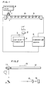
- Fig. 1 shows another apparatus which has been proposed in the art to stabilize the light output of a fluorescent lamp and distribution thereof.
- light emitted directly from a fluorescent lamp 1 and light reflected from an original is received by an optical sensor 2 for monitoring the light output, and an output from the optical sensor 2 is input to a light quantity feedback unit 4 through an amplifier 3.
- An output (tube current control signal) from the light quantity feedback unit 4 is supplied to a fluorescent lamp inverter 5, which in turn supplies appropriate tube current to the fluorescent lamp 1 in response to the tube current control signal.
- the light quantity feedback unit 4 is adapted to control the fluorescent lamp inverter 5 in response to the level of the signal from the optical sensor 2 for adjusting the tube current to be fed to the fluorescent lamp 1, thereby to regularly maintain the output level of the optical sensor 2 at a constant value.
- a cooling device 6 such as a Peltier device is brought into contact with a prescribed tube wall portion of the fluorescent lamp 1, in order to control the position and the temperature of the coldest point of the fluorescent lamp 1.
- a temperature sensor 7 such as a thermistor is interposed between the cooling device 6 and the tube wall.
- the cooling device 6 is controlled by a cooling device driver 8 in response to a value detected by the temperature sensor 7, so that the temperature of the coldest point is maintained at a desired value.
- heaters 9 are serially provided at regular intervals on the tube wall of the fluorescent lamp 1 except for the portion which is in contact with the cooling device 6.
- a temperature sensor 10 such as a thermistor is provided in an appropriate portion of the tube wall of the fluorescent lamp 1.
- the heaters 9 are controlled by temperature control means (not shown) in response to a value detected by the temperature sensor 10, to heat the part of the tube wall of the fluorescent lamp 1 in contact with the heaters 9 up to a prescribed temperature exceeding that of the coldest point.
- the desired effect of stabilizing the light output can be attained with the optical sensor 2 receiving only the light from the fluorescent lamp 1. If the apparatus is applied to an image scanner, however, an error may be caused since the optical sensor 2 receives light reflected by the surface of an original to be duplicated in addition to the light directly received from the fluorescent lamp 1.
- the quantity of light received by the optical sensor 2 is reduced in scanning a high-density region (dark part) of the original as compared with that in scanning a low-density region (bright part), whereby the light quantity feedback unit 4 controls the fluorescent lamp inverter 5 to increase the tube current of the fluorescent lamp 1, similarly to the case where the quantity of light of the fluorescent lamp 1 is reduced.
- the light quantity feedback unit 4 controls the fluorescent lamp inverter 5 to reduce the tube current of the fluorescent lamp 1.
- a principal object of the present invention is to provide an apparatus for and a method of stabilizing the light output of a fluorescent lamp, which can stably maintain the light output of the fluorescent lamp for a prescribed period of time required for scanning an original, without being influenced by variable density of the original to be duplicated.
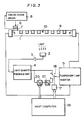
- Fig. 2 schematically illustrates an exemplary original scanner to which the present invention is applied.
- a white reference panel 11 and an original 12 to be duplicated are mounted on an original table (not shown), to be fed in the direction of arrow 13 by appropriate driving means.
- the light is reflected by the white reference panel 11 or the original 12 to be duplicated and its direction is changed by a mirror 14, to be projected on a photoelectric element 16 such as a CCD through a lens 15, for image formation.
- the photoelectric element 16 outputs an image signal of the original 12 to be duplicated.
- the present invention is particularly applicable to a method of and an apparatus for stabilizing the light output of the fluorescent lamp 1 in such a scanner or the like.
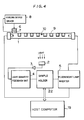
- Fig. 3 is a block diagram showing a first embodiment of the present invention.
- the apparatus is different from the conventional apparatus shown in Fig. 1 in that a switch driver 17, a switch 18, a host computer 19, an A-D converter 20 and a D-A converter 21 are additionally provided.
- An output side of a light quantity feedback unit 4 is connected to an "a" contact side of the switch 18, opening/closing of which is controlled by the switch driver 17.
- the switch driver 17 is controlled by the host computer 19.
- the output side of the light quantity feedback unit 4 is also connected to a "b" contact side of the switch 18 through the A-D converter 20 and the D-A converter 21, and the A-D converter 20 is also controlled by the host computer 19.
- the reference density image is scanned to obtain a suitable tube current control value (step (B)) as well as to hold the value (step (C)), while the tube current of the fluorescent lamp 1 is controlled on the basis of this value when scanning the original to be duplicated, whereby the light output and light distribution of the fluorescent lamp 1 can be stabilized with no influence being exerted by the density of the original to be duplicated.
- the output value of the light quantity feedback unit 4, i.e., the tube current control signal for commanding increase/decrease of the tube current to the fluorescent lamp inverter 5 on the basis of change in the light output of the fluorescent lamp 1, is converted to the digital value thereof by the A-D converter 20 to be transferred to the host computer 19 for display, whereby the time for exchanging the fluorescent lamp 1 can be recognized.
- the tube current of the fluorescent lamp 1 must be increased in order to obtain a constant quantity of light thereof in the last stage of its lifetime.
- the value of the tube current control signal transferred to the host computer 19 is so digitally displayed on display means at the step (C) that the time for exchanging the fluorescent lamp 1 can be extremely precisely recognized when the value exceeds a certain level.
- the converted digital value does not directly indicate the tube current value but the converted digital value of "100” is for the tube current value of "200mA”, and the former of "1000” is for the latter of "400 mA", for example.
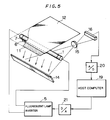
- Fig. 4 is a block diagram showing a second embodiment of the present invention.
- the apparatus shown in Fig. 4 is provided with a sample holder 22 in place of the switch driver 17, the switch 18, the A-D converter 20 and the D-A converter 21 of the first embodiment shown in Fig. 3.
- Other structure of the second embodiment is similar to that of the first embodiment.
- the sample holder 22 is selectively switched by a mode switching signal supplied from host computer 19 to a first mode for passing a tube current control signal output from light quantity feedback unit 4 and a second mode for holding the tube current control signal.
- the sample holder 22 must be such as to have a small droop rate, i.e., there must be no or substantially no change with time in the tube current control signal held in the same.
- the tube current supplied to the fluorescent lamp 1 during scanning of the original has a constant value corresponding to the value of the tube current control signal held in the sample holder 22 at the step (C) similarly to the first embodiment, whereby the light output and light distribution of the fluorescent lamp 1 can be stabilized if the position and temperature of the coldest point are constantly held.
- a line sensor such as a CCD for picking up an image signal in line-sequential scanning on an original is also applied to stabilize/control the light output of the fluorescent lamp.
- Fig. 5 is a perspective view schematically showing the third embodiment.
- a cooling device 6 As shown in Fig. 5, a cooling device 6, a temperature sensor 7 and heaters (not shown) are provided on the tube wall of a fluorescent lamp 1 to constantly hold the position and the temperature of the coldest point, similarly to the embodiments shown in Figs. 3 and 4.
- a scanned plane illuminated by the fluorescent lamp 1 is provided thereon with a white reference panel 11 serving as a reference density image in calibration and with an original 12 to be duplicated in duplication/scanning of an image, so that light reflected by the same is projected on a CCD line sensor 16 by a mirror 14 and a lens 15, for image formation.
- a douser (not shown) is provided on the fluorescent lamp 1, so that no light enters the lens 15, directly.
- An output signal from the CCD line sensor 16 is input to a host computer 19 thorugh an A-D converter 20, so that the host computer 19 outputs a tube current control value to a fluorescent lamp inverter 5 through a D-A converter 21 on the basis of the data.
- the tube current control value is constantly controlled by the host computer 19, whereby the light output and light distribution can be stabilized if the position and temperature of the coldest point are constantly maintained.
- the third embodiment requires no optical sensor since the light output of the fluorescent lamp 1 is detected by the line sensor 16 for scanning the image. Further, the host computer 19 is also adapted to perform feedback control, whereby the light quantity feedback unit, which is required in each of the first and second embodiments, can be omitted.
- the white reference panel 11 (shown in Fig. 2) is employed as a reference density image in each of the aforementioned embodiments, the reference density image is not restricted to the same.
- a gray reference panel may be employed as the reference density image, to obtain a tube current control value for stabilizing the quantity of light.
- Fig. 6 is a block diagram showing an apparatus according to a fourth embodiment of the present invention.
- a heater 24 is provided in contact with a substantially central tube wall portion of a fluorescent lamp 1 except for portions for extracting light from the fluorescent lamp 1, while a thermal conduction buffering member 23, being formed by a heat transfer layer 23a of aluminium etc. and a heat storage layer 23b of glass etc., is provided in contact with an end portion of the tube wall.
- a temperature sensor such as a thermistor is provided on the surface of the heater 24, so that the heater 24 is controlled by temperature control means (not shown) in response to a value detected by the temperature sensor to heat the tube wall of the fluorescent lamp 1 which is in contact with the heater 24 to a prescribed temperature exceeding that of the coldest point, thereby to maintain the tube wall of the fluorescent lamp 1 being in contact with the termal conduction buffering member 23 at a prescribed coldest point temperature.
- Other structure shown in Fig. 6 is similar to that of the apparatus according to the first embodiment.
- the heater 24 is provided entirely over the tube wall of the fluorescent lamp 1 except for the region provided with the thermal conduction buffering member 23 in order to reliably bring the portion provided with the thermal conduction buffering member 23 into the coldest temperature, the same may be replaced by a plurality of heaters which are serially provided at appropriate regularly spaced locations similarly to the first to third embodiments, as a matter of course.
- the heat transfer layer 23a is so connected that one surface thereof is in contact with the tube wall of the fluorescent lamp 1 and the other surface thereof is overlapped with the heat storage layer 23b.
- Silicon grease members (not shown) are interposed in contact surfaces between the heat transfer layer 23a and the fluorescent lamp 1 and between the heat transfer layer 23a and the heat storage layer 23b, respectively.
- Fig. 7 illustrates the structure of the fluorescent lamp 1 shown in Fig. 6 and Fig. 8 is a sectional view taken along the line A - A in Fig. 7, while Fig. 9 is a perspective view showing an end of the fluorescent lamp 1 shown in Fig. 7.
- Two such fluorescent lamps 1 are housed in a casing 25 of aluminium having a U-shaped sectional configuration in a parallel manner, to be fixed by holders 26 provided on both ends of the casing 25.
- Operation of the fourth embodiment is similar to that of the first embodiment shown in Fig. 3 except for a step (A), at which the temperature of the fluorescent lamp 1 is brought into an equilibrium state upon power supply.
- the heater 24 is started upon power supply.
- the heater 24 is so controlled by the temperature control means (not shown) that the surface temperature of the fluorescent lamp 1 measured by the temperature sensor reaches a constant level exceeding the coldest point temperature (48°C).
- the thermal conduction buffering member 23 is in contact with a part of the tube wall of the fluorescent lamp 1 to naturally release heat on the tube wall of the fluorescent lamp 1 to the exterior and cool the same, whereby the said tube wall part of the fluorescent lamp 1 being in contact with the thermal conduction buffering member 23 is cooled to a constant temperature which is lower than the tube wall temperature of the fluorescent lamp 1 in another portion, namely the temperature of the same is the coldest point one.
- Such control of the coldest point temperature is performed continuously during energization of the heater 24, i.e., from start to end of daily operation in general.
- the thermal conduction buffering member 23 for forming the coldest point of the fluorescent lamp 1 is provided with the heat storage layer 23b of low thermal conductivity.
- the ambient temperature of the thermal conduction buffering member 23 is abruptly changed by change in the room temperature etc. during an original scanning interval of about one to two minutes in general, for example, the coldest point of the tube wall of the fluorescent lamp 1 is hardly influenced by the ambient temperature, due to heat storage function of the heat storage layer 23b. Therefore, substantially no fluctuation is caused in the coldest point temperature during the original scanning interval in the aforementioned apparatus, whereby the fluorescent lamp 1 is prevented from changing its light output.
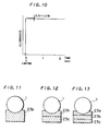
- Fig. 10 is a graph showing the result of a test for measuring actual change in the light output of the fluorescent lamp 1 when the same was turned on after its temperature was brought into an equilibrium state in the apparatus shown in Fig. 6.
- the horizontal axis indicates time elapsed upon lighting, and the vertical axis indicates illuminance at a substantially central portion of the fluorescent lamp 1.
- illuminance reached a certain value shortly after lighting of the fluorescent lamp 1, and then the value was lowered by about 0.5 to 1.0 % to be stabilized at a substantially constant level.
- a similar result was obtained whatever the room temperature was within a range of 10 to 40 (°C).
- the heat storage layer 23b is made of glass in the above embodiment, the same may alternatively be formed of another material having low thermal conductivity.
- Table 1 shows the coldest point temperatures actually measured with heat storage layers 23b of alumina, 18-8 stainless steel and polyethylene at the room temperatures of 10 (°C) and 40 (°C). Table 1 suggests that alumina, 18-8 stainless steel and polyethylene are also employable as materials for the heat storage layer 23b, to attain an effect similar to that of the heat storage layer 23b made of glass.
- control temperatures of the temperature sensor are set at levels higher by several degrees than the temperatures listed in Table 1, in order to ensure the coldest point temperature.
- the luminous efficiency of a fluorescent lamp is at the maximum when the coldest point temperature is about 40 (°C), and is lower in other cases.
- this value has been obtained under such condition that the fluorescent lamp was left in a constant temperature bath maintained at about 40 (°C) for two hours with no preheating means such as a heater, so that the quantity of initial light flux obtained upon lighting of this fluorescent lamp was at the maximum.
- the coldest point temperature is preferably maintained at about 40 (°C) under different condition such as that of continuous lighting.
- the position and temperature of the coldest point of the fluorescent lamp 1 are controlled by the cooling device 6, the temperature sensor 7 and the cooling device driver 8 shown in Fig. 4 or 5 in each of the second and third embodiments, such control may be performed by bringing a thermal conduction buffering member 23, which is formed by a heat transfer layer 23a of aluminium etc. and a heat storage layer 23b of glass etc., into contact with a prescribed position on the tube wall of a fluorescent lamp 1 similarly to the fourth embodiment.
- heaters 9 are serially provided at appropriately spaced locations on a tube wall region of the fluorescent lamp 1 other than a region being in contact with the thermal conduction buffering member 23 similarly to the second or third embodiment, in order to reliably bring the portion provided with the thermal conduction buffering member 23 into the coldest point.
- a heater may alternatively be provided entirely over such a region, similarly to the fourth embodiment.
- a thermal conduction buffering member 23 may be formed only by a heat storage layer 23b shown in Fig. 11.
- a thermal conduction buffering member 23 may be formed by a heat radiation layer 23c of a material having high thermal conductivity such as aluminium and a heat storage layer 23b shown in Fig. 12, with the heat storage layer 23b being in contact with the tube wall of a fluorescent lamp 1.
- a heat transfer layer 23a and a heat radiation layer 23c may be overlapped on both sides of a heat storage layer 23b to form a thermal conduction buffering member 23 shown in Fig. 13, with the heat transfer layer 23a being brought into contact with the tube wall of a fluorescent lamp 1.
- a thermal conduction buffering member 23 shown in Fig. 13 With the heat transfer layer 23a being brought into contact with the tube wall of a fluorescent lamp 1.
- the present invention is not restricted to this but applicable to a purely optical scanner, which projects an original image on a photosensitive material surface through an image forming lens.
Landscapes
- Physics & Mathematics (AREA)
- General Physics & Mathematics (AREA)
- Light Sources And Details Of Projection-Printing Devices (AREA)
- Facsimile Scanning Arrangements (AREA)
Claims (12)
- Vorrichtung zum Stabilisieren der Lichtleistung einer Fluoreszenzlampe zum Beleuchten eines abzutastenden Gegenstandes, mit
einem Bezugs-Dichtebild (11), das so angeordnet ist, daß es anstelle des Gegenstandes (12) von der Lampe (1) beleuchtet wird; einer Lichtmengen-Detektorvorrichtung (2), die die direkt von der Lampe (1) emittierte Lichtmenge und die von dem Bezugs-Dichtebilde (11) reflektierte Lichtmenge erfaßt und einen Lichtmengenwert ausgibt;
einer Rückführungsvorrichtung (4, 5), die so angeordnet ist, daß sie in einem ersten Modus, wenn das Bezugs-Dichtebild (11) beleuchtet wird, den Röhrenstrom durch die Lampe auf der Basis des Lichtmengenwertes steuert, bis ein konstanter Wert erreicht ist;
gekennzeichnet durch eine Vorrichtung (19) zum Halten des konstanten Wertes, wenn der erfaßte Lichtmengenwert den konstanten Wert erreicht, und zum Umschalten der Rückführungsvorrichtung (4, 5) in einen zweiten Modus, in dem der Röhrenstrom auf der Basis dieses gehaltenen Wertes gesteuert wird. - Vorrichtung nach Anspruch 1, gekennzeichnet durch eine Einstellvorrichtung (6 bis 10; 23, 24) für einen kältesten Punkt, die eine vorgegebene Stelle an der Röhrenwand der Fluoreszenzlampe (1) bei einer konstanten Oberflächentemperatur hält, die unter der Oberflächentemperatur einer anderen Stelle an der Röhrenwand liegt.
- Vorrichtung nach Anspruch 2, dadurch gekennzeichnet, daß die Einstellvorrichtung für den kältesten Punkt folgende Merkmale aufweist:
eine Heiz/Steuervorrichtung (9, 10) zum Erfassen der Oberflächentemperatur der Röhrenwand der Fluoreszenzlampe (1) und zum Erwärmen einer erforderlichen Stelle auf der Röhrenwand der Fluoreszenzlampe (1) auf eine vorgegebene Temperatur, die höher ist als die Temperatur am kältesten Punkt der Fluoreszenzlampe (1);
eine Kühlvorrichtung (6), die einen anderen Bereich der Röhrenwand der Fluoreszenzlampe (1) als den von der Heiz/Steuervorrichtung (9, 10) beheizte Bereich berührt, zum Kühlen des Kontaktbereiches der Kühlvorrichtung (6), um dadurch einen kältesten Punkt zu bilden;
einen Temperatursensor (7) zum Erfassen der Temperatur des kältesten Punktes, um ein der Temperatur des kältesten Punktes entsprechendes Signal auszugeben; und
eine Kühlvorrichtungs-Ansteuerung (8) zum Ansteuern der Kühlvorrichtung (6), um auf der Basis des Ausgangssignals von dem Temperatursensor (7) einen kältesten Punkt mit konstanter Temperatur zu erhalten. - Vorrichtung nach Anspruch 2, dadurch gekennzeichnet, daß die Einstellvorrichtung für den kältesten Punkt folgende Merkmale aufweist:
eine Heiz/Steuervorrichtung (9, 10) zum Erfassen der Oberflächentemperatur der Röhrenwand der Fluoreszenzlampe (1) und zum Erwärmen einer erforderlichen Stelle der Röhrenwand der Fluoreszenzlampe (1) auf eine vorgegebene Temperatur, die höher ist als die Temperatur des kältesten Punktes der Fluoreszenzlampe (1);
eine Wärmeleitungs-Puffervorrichtung (23), die einen anderen Bereich der Röhrenwand der Fluoreszenzlampe (1) als den von der Heiz/Steuervorrichtung (23) beheizte Bereich berührt, um den Kontaktbereich der Wärmeleitungs-Puffervorrichtung (23) zum kältesten Punkt zu machen. - Vorrichtung nach Anspruch 4, dadurch gekennzeichnet, daß die Wärmeleitungs-Puffervorrichtung (23) ferner eine Wärmeübertragungsschicht (23a) aufweist, die von der Wärmespeicherschicht (23b) überdeckt wird und eine höhere thermische Leitfähigkeit aufweist als die Wärmespeicherschicht (23b), wobei die Wärmeübertragungsschicht (23a) der Wärmeleitungs-Puffervorrichtung (23) die Röhrenwand der Fluoreszenzlampe (1) berührt.
- Vorrichtung nach Anspruch 4 oder 5, dadurch gekennzeichnet, daß die Wärmeleitungs-Puffervorrichtung (23) ferner eine Wärmestrahlungsschicht (23c) aufweist, die von der Wärmespeicherschicht (23b) überdeckt wird und eine höhere Wärmeleitfähigkeit aufweist als die Wärmespeicherschicht (23b), wobei die Wärmespeicherschicht (23b) der Wärmeleitungs-Puffervorrichtung (23) die Röhrenwand der Fluoreszenzlampe (1) berührt.
- Vorrichtung nach Anspruch 4, bei der die Wärmeleitungs-Puffervorrichtung (23) ferner eine Wärmeübertragungsschicht (23a) und eine Wärmestrahlungsschicht (23c) aufweist, die jeweils auf beiden Seiten der Wärmespeicherschicht (23b) überdeckt werden und eine höhere Wärmeleitfähigkeit haben als die Wärmespeicherschicht (23b), wobei die Wärmeübertragungsschicht (23a) der Wärmeleitungs-Puffervorrichtung die Röhrenwand der Fluoreszenzlampe (1) berührt.
- Vorrichtung nach einem der vorangehenden Ansprüche, dadurch gekennzeichnet, daß die Rückführungsvorrichtung (5, 19) folgende Merkmale aufweist:
einen Fluoreszenzlampeninvertierer (5) zum Einstellen des in der Fluoreszenzlampe (1) fließenden Röhrenstromes,
eine Lichtmengen-Rückführungseinheit (4) zum Ausgeben eines ersten analogen Röhrenstrom-Steuersignals zum Steuern des Fluoreszenzlampen-Invertierers (5), so daß ein Detektorsignal von der Lichtmengen-Detektorvorrichtung (2) einen konstanten Wert erreicht,
einen Analog-Digital-Umsetzer (20) zum Umsetzen des ersten analogen Röhrenstrom-Steuersignals von der Lichtmengen-Rückführungseinheit (4) in ein digitales Röhrenstrom-Steuersignal,
einen Digital-Analog-Umsetzer (21) zum Umsetzen des digitalen Röhrenstrom-Steuersignals von dem Analog-Digital-Umsetzer (20) in ein zweites analoges Röhrenstrom-Steuersignal,
einen Schalter (18), um wahlweise einen ersten Modus zum Zuführen des ersten analogen Röhrenstrom-Steuersignales von der Lichtmengen-Rückführungseinheit (4) zu dem Fluoreszenzlampen-Invertierer (5) und einen zweiten Modus zum Zuführen des zweiten analogen Röhrenstrom-Steuersignales von den Digital-Analog-Umsetzer (21) zum Fluoreszenzlampen-Invertierer (5) einzuschalten,
eine Schalter-Ansteuerungsvorrichtung (17) zum Steuern des Schaltbetriebs des Schalters (18),
eine Vorrichtung (19) zum Schalten des Schalters (18) in den ersten Modus über die Schalter-Ansteuervorrichtung (17), so daß die Lichtmengen-Rückführungseinheit (4) den Fluoreszenzlampen-Invertierer (5) steuert, so daß der Röhrenstrom auf der Basis des Detektorsignales der Lichtmengen-Detektorvorrichtung (2) einen konstanten Wert erreicht, eine Vorrichtung (19) zum Umsetzen des ersten Röhrenstrom-Steuersignales von der Lichtmengen-Rückführungseinheit (4) in das digitale Röhrenstrom-Steuersignal durch den Analog-Digital-Umsetzer (20), nachdem der Röhrenstrom den konstanten Wert erreicht hat, um einen umgesetzten Wert des digitalen Röhrenstrom-Steuersignales zu halten, und
eine Vorrichtung (19) zum Schalten des Schalters (18) in den zweiten Modus über die Schalter-Ansteuervorrichtung (18), um den von dem Digital-Analog-Umsetzer (21) umgesetzten Wert des digitalen Röhrenstrom-Steuersignales in das zweite analoge Röhrenstrom-Steuersignal umzusetzen und das zweite analoge Röhrenstrom-Steuersignal dem Fluoreszenzlampen-Invertierer (5) als ein Steuersignal zum Steuern des Fluoreszenzlampen-Invertierers (5) zuzuführen. - Vorrichtung nach einem der Ansprüche 1 bis 7, dadurch gekennzeichnet, daß die Rückführungsvorrichtung (5, 19) folgende Merkmale aufweist:
einen Fluoreszenzlampen-Invertierer (5) zum Einstellen des in der Fluoreszenzlampe (1) fließenden Röhrenstromes,
eine Lichtmengen-Rückführungseinheit (4) zum Ausgeben eines Röhrenstrom-Steuersignales zum Steuern des Fluoreszenzlampen-Invertierers (5), so daß ein Detektorsignal von der Lichtmengen-Detektorvorrichtung (2) einen konstanten Wert erreicht,
eine Abtastwert-Haltevorrichtung (22), die wahlweise in einen ersten Modus geschaltet wird, um das Röhrenstrom-Steuersignal von der Lichtmengen-Rückführungseinheit (4) weiterzugeben, und in einen zweiten Modus, um das Röhrenstrom-Steuersignal zu halten,
eine Vorrichtung (19) zum Liefern eines ersten Modus-Schaltsignales zur Abtastwert-Haltevorrichtung (22), um die Abtastwert-Haltevorrichtung in den ersten Modus zu schalten, so daß die Lichtmengen-Rückführungseinheit (4) den Fluoreszenzlampen-Invertierer (5) steuert, so daß der Röhrenstrom auf der Basis des Detektorsignals von der Lichtmengen-Detektorvorrichtung (2) den konstanten Wert erreicht, und
eine Vorrichtung (19) zum Liefern eines zweiten Modus-Schaltsignals an die Abtastwert-Haltevorrichtung (22), nachdem der Röhrenstrom den konstanten Wert erreicht hat, um die Abtastwert-Haltevorrichtung (22) in den zweiten Modus zu schalten, so daß die Abtast-Haltevorrichtung (22) sowohl das Röhrenstrom-Steuersignal hält als auch das von der Abtastwert-Haltevorrichtung (22) gehaltene Röhrenstrom-Steuersignal an den Fluoreszenzlampen-Invertierer (5) übergibt. - Vorrichtung nach einem der Ansprüche 1 bis 7, dadurch gekennzeichnet, daß die Rückführungsvorrichtung (5, 19) folgende Merkmale aufweist:
eine von der Fluoreszenzlampe (1) beleuchtete Abtastebene (11, 12),
ein Linsensystem (14, 15) zum Durchführen einer Bildgestaltung durch das von der Abtastebene (11, 12) bei einer vorgegebenen Position reflektierte Licht,
ein lichtempfangendes Element (16) zum Empfangen des der Bildgestaltung durch das Linsensystem (14, 15) unterworfenen Lichtes: einen Analog-Digital-Umsetzer (20) zum Umsetzen eines analogen Signales von dem lichtempfangenden Element (16) in ein digitales Signal,
eine Vorrichtung (19) zum Erzeugen eines digitalen Röhrenstrom-Steuersignales eines vorgegebenen Wertes,
einen Digital-Analog-Umsetzer (21) zum Umsetzen des digitalen Röhrenstrom-Steuersignales in ein analoges Röhrenstrom-Steuersignal,
einen Fluoreszenzlampen-Invertierer (5) zum Steuern des Röhrenstromes auf der Basis des vom Digital-Analog-Umsetzer (21) umgesetzten analogen Röhrenstrom-Steuersignales, und
eine Vorrichtung (19) zum Verändern des vorgegebenen Wertes des digitalen Röhrenstrom-Steuersignales auf der Basis des digitalen Signales vom Analog-Digital-Umsetzer (20), so daß das digitale Röhrenstrom-Steuersignal vom Analog-Digital-Umsetzer (20) einen konstanten Wert erreicht, und zum Liefern des Röhrenstrom-Steuersignales mit dem veränderten vorgegebenen Wert zum Digital-Analog-Umsetzer (21). - Verfahren zum Stabilisieren der Lichtleistung einer Fluoreszenzlampe zum Beleuchten eines abzutastenden Gegenstandes, mit folgenden Verfahrensschritten:
Anordnen eines Bezugs-Dichtebildes (11), so daß es anstelle des Gegenstandes (12) von der Fluoreszenzlampe (1) beleuchtet wird,
Erfassen der direkt von der Lampe (1) emittierten Lichtmenge und der von dem Bezugs-Dichtebild (11) reflektierten Lichtmenge und Ausgeben eines Lichtmengenwertes,
Steuern des Röhrenstromes durch die Lampe in einen ersten Modus auf der Basis des Lichtmengenwertes, bis ein konstanter Wert erreicht wird,
gekennzeichnet durch Halten des konstanten Wertes, wenn der Lichtmengenwert den konstanten Wert erreicht, und Umschalten in einen zweiten Modus, in dem der Röhrenstrom auf der Basis des gehaltenen Wertes gesteuert wird. - Verfahren nach Anspruch 11, dadurch gekennzeichnet, daß eine vorgegebene Position auf der Röhrenwand der Fluoreszenzlampe (1) bei einer konstanten Oberflächentemperatur gehalten wird, die niedriger ist als die anderer Röhrenwandbereiche.
Priority Applications (1)
| Application Number | Priority Date | Filing Date | Title |
|---|---|---|---|
| EP91114661A EP0460719B1 (de) | 1987-06-04 | 1988-05-31 | Gerät zur Stabilisierung der Lichtmenge einer Fluoreszenzlampe |
Applications Claiming Priority (4)
| Application Number | Priority Date | Filing Date | Title |
|---|---|---|---|
| JP139008/87 | 1987-06-04 | ||
| JP62139008A JPH0786650B2 (ja) | 1987-06-04 | 1987-06-04 | 原画走査装置における蛍光灯光量安定化方法及び装置 |
| JP15075/88 | 1988-01-25 | ||
| JP1507588A JPH01189804A (ja) | 1988-01-25 | 1988-01-25 | 蛍光灯の光量安定化装置 |
Related Child Applications (1)
| Application Number | Title | Priority Date | Filing Date |
|---|---|---|---|
| EP91114661.1 Division-Into | 1988-05-31 |
Publications (2)
| Publication Number | Publication Date |
|---|---|
| EP0295491A1 EP0295491A1 (de) | 1988-12-21 |
| EP0295491B1 true EP0295491B1 (de) | 1993-08-18 |
Family
ID=26351155
Family Applications (2)
| Application Number | Title | Priority Date | Filing Date |
|---|---|---|---|
| EP88108716A Expired - Lifetime EP0295491B1 (de) | 1987-06-04 | 1988-05-31 | Gerät und Verfahren zur Stabilisierung der Lichtmenge einer Fluoreszenzlampe |
| EP91114661A Expired - Lifetime EP0460719B1 (de) | 1987-06-04 | 1988-05-31 | Gerät zur Stabilisierung der Lichtmenge einer Fluoreszenzlampe |
Family Applications After (1)
| Application Number | Title | Priority Date | Filing Date |
|---|---|---|---|
| EP91114661A Expired - Lifetime EP0460719B1 (de) | 1987-06-04 | 1988-05-31 | Gerät zur Stabilisierung der Lichtmenge einer Fluoreszenzlampe |
Country Status (3)
| Country | Link |
|---|---|
| US (1) | US4870454A (de) |
| EP (2) | EP0295491B1 (de) |
| DE (2) | DE3883302T2 (de) |
Families Citing this family (15)
| Publication number | Priority date | Publication date | Assignee | Title |
|---|---|---|---|---|
| JPH0218857A (ja) * | 1988-07-04 | 1990-01-23 | Japan Aviation Electron Ind Ltd | 蛍光ランプ装置 |
| JP2599987B2 (ja) * | 1989-02-22 | 1997-04-16 | 三田工業株式会社 | 画像形成装置 |
| US5150154A (en) * | 1989-08-22 | 1992-09-22 | Brother Kogyo Kabushiki Kaisha | Apparatus for forming images discharge lamp and current, tone and temperature control means |
| JP2905229B2 (ja) * | 1989-09-26 | 1999-06-14 | キヤノン株式会社 | 光ビーム駆動装置 |
| JP2714205B2 (ja) * | 1990-02-17 | 1998-02-16 | キヤノン株式会社 | 複写装置 |
| US5038028A (en) * | 1990-05-18 | 1991-08-06 | Hewlett-Packard Company | Optical scanner aperture and light source assembly |
| US5095336A (en) * | 1990-11-08 | 1992-03-10 | Xerox Corporation | Temperature control of a fluorescent lamp having a central and two end amalgam patches |
| JPH04309064A (ja) * | 1991-04-05 | 1992-10-30 | Fuji Xerox Co Ltd | 画像読取装置 |
| US5327171A (en) * | 1992-05-26 | 1994-07-05 | United Parcel Service Of America, Inc. | Camera system optics |
| US5406070A (en) * | 1993-12-16 | 1995-04-11 | International Business Machines Corporation | Method and apparatus for scanning an object and correcting image data using concurrently generated illumination data |
| US5902994A (en) * | 1997-05-06 | 1999-05-11 | Eastman Kodak Company | Apparatus for calibrating a linear image sensor |
| JP5173120B2 (ja) * | 2005-05-23 | 2013-03-27 | オリンパスメディカルシステムズ株式会社 | 内視鏡装置 |
| KR101158006B1 (ko) * | 2007-08-07 | 2012-06-25 | 삼성전자주식회사 | 스캐닝 장치 및 이를 위한 기준광량 결정방법 |
| JP2010161719A (ja) * | 2009-01-09 | 2010-07-22 | Nec Engineering Ltd | 画像読取装置 |
| US8717194B2 (en) | 2010-12-21 | 2014-05-06 | GE Lighting Solutions, LLC | LED traffic signal compensation and protection methods |
Family Cites Families (7)
| Publication number | Priority date | Publication date | Assignee | Title |
|---|---|---|---|---|
| JPS5182630A (de) * | 1975-01-16 | 1976-07-20 | Minolta Camera Kk | |
| US4024428A (en) * | 1975-05-19 | 1977-05-17 | Optical Associates, Incorporated | Radiation-sensitive control circuit for driving lamp at various power levels |
| JPS58187920A (ja) * | 1982-04-28 | 1983-11-02 | Konishiroku Photo Ind Co Ltd | 複写機の原稿照明装置 |
| US4533854A (en) * | 1983-03-25 | 1985-08-06 | Xerox Corporation | Mechanism and method for controlling the temperature and output of a fluorescent lamp |
| US4529912A (en) * | 1983-03-25 | 1985-07-16 | Xerox Corporation | Mechanism and method for controlling the temperature and light output of a fluorescent lamp |
| US4624547A (en) * | 1983-06-28 | 1986-11-25 | Canon Kabushiki Kaisha | Image forming apparatus |
| JPH0618414B2 (ja) * | 1985-03-30 | 1994-03-09 | 株式会社東芝 | カラ−画像読み取り装置 |
-
1988
- 1988-05-31 EP EP88108716A patent/EP0295491B1/de not_active Expired - Lifetime
- 1988-05-31 DE DE88108716T patent/DE3883302T2/de not_active Expired - Fee Related
- 1988-05-31 DE DE3854653T patent/DE3854653T2/de not_active Expired - Fee Related
- 1988-05-31 EP EP91114661A patent/EP0460719B1/de not_active Expired - Lifetime
- 1988-06-06 US US07/202,985 patent/US4870454A/en not_active Expired - Fee Related
Non-Patent Citations (4)
| Title |
|---|
| PATENT ABSTRACTS OF JAPAN, vol. 10, no. 282 (P500)(2338), 25th September 1986; & JP-A-61 102 659 * |
| PATENT ABSTRACTS OF JAPAN, vol. 10, no. 41 (P-429)(2098), 18th February 1986; JP-A-60 186 82859 * |
| PATENT ABSTRACTS OF JAPAN, vol. 8, no. 144 (P-284)(1581), 5th July 1984; & JP-A-59 4253486 82859 * |
| XEROX DISCLOSURE JOURNAL, vol. 10, no. 5, September/October 1985, pages 297-298; S.C: CORONA "Fluorescent lamp illumination control" * |
Also Published As
| Publication number | Publication date |
|---|---|
| EP0460719A3 (en) | 1992-08-26 |
| US4870454A (en) | 1989-09-26 |
| EP0460719B1 (de) | 1995-11-02 |
| EP0460719A2 (de) | 1991-12-11 |
| DE3854653D1 (de) | 1995-12-07 |
| EP0295491A1 (de) | 1988-12-21 |
| DE3854653T2 (de) | 1996-03-21 |
| DE3883302T2 (de) | 1994-03-31 |
| DE3883302D1 (de) | 1993-09-23 |
Similar Documents
| Publication | Publication Date | Title |
|---|---|---|
| EP0295491B1 (de) | Gerät und Verfahren zur Stabilisierung der Lichtmenge einer Fluoreszenzlampe | |
| US5063462A (en) | LED array and partitive driving method therefor using overlapping activation periods | |
| CN1333303C (zh) | Led光源的温度调节装置 | |
| JPH06348824A (ja) | 照明強度の安定度検出方法および装置 | |
| EP0158288B1 (de) | Fotoelektrisches Lesegerät | |
| JPH04267046A (ja) | アマルガム蛍光ランプの監視/制御装置 | |
| US20080043298A1 (en) | Image reading apparatus | |
| US5654809A (en) | Method and apparatus for dynamic white point adjustment | |
| JP3631100B2 (ja) | 画像読取装置、及び画像読取方法 | |
| JPH05181211A (ja) | 投影面を均一照明する装置及び方法 | |
| JPH0786650B2 (ja) | 原画走査装置における蛍光灯光量安定化方法及び装置 | |
| JP2699477B2 (ja) | 画像読み取り装置 | |
| JPS60124168A (ja) | 原稿読み取り装置 | |
| CN2297749Y (zh) | 免预热式影像扫描装置 | |
| JPS63196158A (ja) | 画像読取装置 | |
| JPH01189804A (ja) | 蛍光灯の光量安定化装置 | |
| JPH06268815A (ja) | 画像読取り装置 | |
| JPH03297266A (ja) | 画像読取装置 | |
| JP3301783B2 (ja) | 画像読取装置 | |
| JPH04200064A (ja) | 画像入力装置等の光源制御装置 | |
| JP2003069794A (ja) | 画像読取装置 | |
| JPS63302663A (ja) | 画像読取装置 | |
| JPS63157139A (ja) | 蛍光灯の光量保証装置 | |
| JPS61154358A (ja) | 情報読取装置 | |
| JPH02308664A (ja) | カラー読取装置 |
Legal Events
| Date | Code | Title | Description |
|---|---|---|---|
| PUAI | Public reference made under article 153(3) epc to a published international application that has entered the european phase |
Free format text: ORIGINAL CODE: 0009012 |
|
| 17P | Request for examination filed |
Effective date: 19880531 |
|
| AK | Designated contracting states |
Kind code of ref document: A1 Designated state(s): DE FR GB |
|
| 17Q | First examination report despatched |
Effective date: 19910508 |
|
| GRAA | (expected) grant |
Free format text: ORIGINAL CODE: 0009210 |
|
| AK | Designated contracting states |
Kind code of ref document: B1 Designated state(s): DE FR GB |
|
| ET | Fr: translation filed | ||
| REF | Corresponds to: |
Ref document number: 3883302 Country of ref document: DE Date of ref document: 19930923 |
|
| PLBE | No opposition filed within time limit |
Free format text: ORIGINAL CODE: 0009261 |
|
| STAA | Information on the status of an ep patent application or granted ep patent |
Free format text: STATUS: NO OPPOSITION FILED WITHIN TIME LIMIT |
|
| 26N | No opposition filed | ||
| PGFP | Annual fee paid to national office [announced via postgrant information from national office to epo] |
Ref country code: FR Payment date: 19980511 Year of fee payment: 11 |
|
| PGFP | Annual fee paid to national office [announced via postgrant information from national office to epo] |
Ref country code: GB Payment date: 19980522 Year of fee payment: 11 |
|
| PGFP | Annual fee paid to national office [announced via postgrant information from national office to epo] |
Ref country code: DE Payment date: 19980608 Year of fee payment: 11 |
|
| PG25 | Lapsed in a contracting state [announced via postgrant information from national office to epo] |
Ref country code: GB Free format text: LAPSE BECAUSE OF NON-PAYMENT OF DUE FEES Effective date: 19990531 |
|
| GBPC | Gb: european patent ceased through non-payment of renewal fee |
Effective date: 19990531 |
|
| PG25 | Lapsed in a contracting state [announced via postgrant information from national office to epo] |
Ref country code: FR Free format text: LAPSE BECAUSE OF NON-PAYMENT OF DUE FEES Effective date: 20000131 |
|
| PG25 | Lapsed in a contracting state [announced via postgrant information from national office to epo] |
Ref country code: DE Free format text: LAPSE BECAUSE OF NON-PAYMENT OF DUE FEES Effective date: 20000301 |
|
| REG | Reference to a national code |
Ref country code: FR Ref legal event code: ST |