EP0295609A2 - Bobinages de circuits imprimés par capteurs d'induction blindés, notamment capteurs de la mesure de niveau - Google Patents
Bobinages de circuits imprimés par capteurs d'induction blindés, notamment capteurs de la mesure de niveau Download PDFInfo
- Publication number
- EP0295609A2 EP0295609A2 EP88109385A EP88109385A EP0295609A2 EP 0295609 A2 EP0295609 A2 EP 0295609A2 EP 88109385 A EP88109385 A EP 88109385A EP 88109385 A EP88109385 A EP 88109385A EP 0295609 A2 EP0295609 A2 EP 0295609A2
- Authority
- EP
- European Patent Office
- Prior art keywords
- winding
- sense
- conductive screen
- drive
- sensor
- Prior art date
- Legal status (The legal status is an assumption and is not a legal conclusion. Google has not performed a legal analysis and makes no representation as to the accuracy of the status listed.)
- Withdrawn
Links
Images


Classifications
-
- H—ELECTRICITY
- H10—SEMICONDUCTOR DEVICES; ELECTRIC SOLID-STATE DEVICES NOT OTHERWISE PROVIDED FOR
- H10D—INORGANIC ELECTRIC SEMICONDUCTOR DEVICES
- H10D86/00—Integrated devices formed in or on insulating or conducting substrates, e.g. formed in silicon-on-insulator [SOI] substrates or on stainless steel or glass substrates
- H10D86/80—Integrated devices formed in or on insulating or conducting substrates, e.g. formed in silicon-on-insulator [SOI] substrates or on stainless steel or glass substrates characterised by multiple passive components, e.g. resistors, capacitors or inductors
- H10D86/85—Integrated devices formed in or on insulating or conducting substrates, e.g. formed in silicon-on-insulator [SOI] substrates or on stainless steel or glass substrates characterised by multiple passive components, e.g. resistors, capacitors or inductors characterised by only passive components
-
- G—PHYSICS
- G01—MEASURING; TESTING
- G01D—MEASURING NOT SPECIALLY ADAPTED FOR A SPECIFIC VARIABLE; ARRANGEMENTS FOR MEASURING TWO OR MORE VARIABLES NOT COVERED IN A SINGLE OTHER SUBCLASS; TARIFF METERING APPARATUS; MEASURING OR TESTING NOT OTHERWISE PROVIDED FOR
- G01D5/00—Mechanical means for transferring the output of a sensing member; Means for converting the output of a sensing member to another variable where the form or nature of the sensing member does not constrain the means for converting; Transducers not specially adapted for a specific variable
- G01D5/12—Mechanical means for transferring the output of a sensing member; Means for converting the output of a sensing member to another variable where the form or nature of the sensing member does not constrain the means for converting; Transducers not specially adapted for a specific variable using electric or magnetic means
- G01D5/14—Mechanical means for transferring the output of a sensing member; Means for converting the output of a sensing member to another variable where the form or nature of the sensing member does not constrain the means for converting; Transducers not specially adapted for a specific variable using electric or magnetic means influencing the magnitude of a current or voltage
- G01D5/20—Mechanical means for transferring the output of a sensing member; Means for converting the output of a sensing member to another variable where the form or nature of the sensing member does not constrain the means for converting; Transducers not specially adapted for a specific variable using electric or magnetic means influencing the magnitude of a current or voltage by varying inductance, e.g. by a movable armature
-
- G—PHYSICS
- G01—MEASURING; TESTING
- G01F—MEASURING VOLUME, VOLUME FLOW, MASS FLOW OR LIQUID LEVEL; METERING BY VOLUME
- G01F23/00—Indicating or measuring liquid level or level of fluent solid material, e.g. indicating in terms of volume or indicating by means of an alarm
- G01F23/30—Indicating or measuring liquid level or level of fluent solid material, e.g. indicating in terms of volume or indicating by means of an alarm by floats
- G01F23/32—Indicating or measuring liquid level or level of fluent solid material, e.g. indicating in terms of volume or indicating by means of an alarm by floats using rotatable arms or other pivotable transmission elements
- G01F23/36—Indicating or measuring liquid level or level of fluent solid material, e.g. indicating in terms of volume or indicating by means of an alarm by floats using rotatable arms or other pivotable transmission elements using electrically actuated indicating means
-
- H—ELECTRICITY
- H01—ELECTRIC ELEMENTS
- H01F—MAGNETS; INDUCTANCES; TRANSFORMERS; SELECTION OF MATERIALS FOR THEIR MAGNETIC PROPERTIES
- H01F41/00—Apparatus or processes specially adapted for manufacturing or assembling magnets, inductances or transformers; Apparatus or processes specially adapted for manufacturing materials characterised by their magnetic properties
- H01F41/02—Apparatus or processes specially adapted for manufacturing or assembling magnets, inductances or transformers; Apparatus or processes specially adapted for manufacturing materials characterised by their magnetic properties for manufacturing cores, coils, or magnets
- H01F41/04—Apparatus or processes specially adapted for manufacturing or assembling magnets, inductances or transformers; Apparatus or processes specially adapted for manufacturing materials characterised by their magnetic properties for manufacturing cores, coils, or magnets for manufacturing coils
- H01F41/041—Printed circuit coils
- H01F41/045—Trimming
-
- H—ELECTRICITY
- H05—ELECTRIC TECHNIQUES NOT OTHERWISE PROVIDED FOR
- H05K—PRINTED CIRCUITS; CASINGS OR CONSTRUCTIONAL DETAILS OF ELECTRIC APPARATUS; MANUFACTURE OF ASSEMBLAGES OF ELECTRICAL COMPONENTS
- H05K3/00—Apparatus or processes for manufacturing printed circuits
- H05K3/0002—Apparatus or processes for manufacturing printed circuits for manufacturing artworks for printed circuits
-
- H—ELECTRICITY
- H01—ELECTRIC ELEMENTS
- H01F—MAGNETS; INDUCTANCES; TRANSFORMERS; SELECTION OF MATERIALS FOR THEIR MAGNETIC PROPERTIES
- H01F17/00—Fixed inductances of the signal type
- H01F17/0006—Printed inductances
- H01F2017/0053—Printed inductances with means to reduce eddy currents
-
- H—ELECTRICITY
- H05—ELECTRIC TECHNIQUES NOT OTHERWISE PROVIDED FOR
- H05K—PRINTED CIRCUITS; CASINGS OR CONSTRUCTIONAL DETAILS OF ELECTRIC APPARATUS; MANUFACTURE OF ASSEMBLAGES OF ELECTRICAL COMPONENTS
- H05K1/00—Printed circuits
- H05K1/16—Printed circuits incorporating printed electric components, e.g. printed resistors, capacitors or inductors
- H05K1/165—Printed circuits incorporating printed electric components, e.g. printed resistors, capacitors or inductors incorporating printed inductors
-
- H—ELECTRICITY
- H05—ELECTRIC TECHNIQUES NOT OTHERWISE PROVIDED FOR
- H05K—PRINTED CIRCUITS; CASINGS OR CONSTRUCTIONAL DETAILS OF ELECTRIC APPARATUS; MANUFACTURE OF ASSEMBLAGES OF ELECTRICAL COMPONENTS
- H05K2203/00—Indexing scheme relating to apparatus or processes for manufacturing printed circuits covered by H05K3/00
- H05K2203/05—Patterning and lithography; Masks; Details of resist
- H05K2203/0548—Masks
- H05K2203/056—Using an artwork, i.e. a photomask for exposing photosensitive layers
-
- Y—GENERAL TAGGING OF NEW TECHNOLOGICAL DEVELOPMENTS; GENERAL TAGGING OF CROSS-SECTIONAL TECHNOLOGIES SPANNING OVER SEVERAL SECTIONS OF THE IPC; TECHNICAL SUBJECTS COVERED BY FORMER USPC CROSS-REFERENCE ART COLLECTIONS [XRACs] AND DIGESTS
- Y10—TECHNICAL SUBJECTS COVERED BY FORMER USPC
- Y10S—TECHNICAL SUBJECTS COVERED BY FORMER USPC CROSS-REFERENCE ART COLLECTIONS [XRACs] AND DIGESTS
- Y10S73/00—Measuring and testing
- Y10S73/05—Liquid levels with magnetic transmission
Definitions
- This invention relates to screened inductance sensors.
- the invention relates in particular to printed circuit windings for screened inductance sensors including, but not limited to, level gauge sensors having sealing barriers, and to methods for the production of such windings, as well as to screened inductance transducer geometries in which there is a sealing barrier between the windings and the screen(s), especially screened inductance sensors for liquid level measurement.
- a screened inductance sensor is a position measurement device in which inductive coupling between two, normally stationary, coils is controlled by the position of a passive conductive screen.
- a sensor comprising a drive or exciting winding for establishing a forward or drive field, at least one secondary or sense winding in which a voltage may be induced in the presence of said forward or drive field, and at least one conductive screen within which eddy currents are generated in the presence of said forward or drive field to establish a counter-field opposing said forward or drive field, said at least one conductive screen and said at least one secondary or sense winding being displaceable relative to one another within said forward or drive field so that said at least one secondary or sense winding may be shaded by said at least one conductive screen to a varying extent to thereby vary the voltage induced in said at least one secondary or sense winding, the relative displacement of said at least one conductive screen and said at least one secondary or sense winding being limited to substantially
- Said surface region of said at least one conductive screen may be substantially planar and said at least one secondary or sense winding may be a substantially flat winding defining a plane substantially parallel to said surface region.
- Said at least one screen and said at least one secondary or sense winding may then suitably be relatively linearly displaceable, or alternatively, they may be relatively rotationally displaceable.
- Said surface region of said at least one conductive screen may be a sector of a cylindrical surface and said at least one secondary or sense winding may be disposed about the periphery of a notional cylinder substantially concentric with said cylindrical sector surface region, said at least one conductive screen and said at least one secondary or sense winding then being relatively displaceable in a circumferential direction about the substantially common axis of said cylindrical surface and said notional cylinder.
- a further secondary or sense winding the progressive shading of which during said relative displacement of said at least one conductive screen and said at least one secondary or sense winding proceeds in a manner substantially identical with the progressive shading of said at least one secondary or sense winding during said relative displacement, said further secondary or sense winding being disposed relative to said at least one secondary or sense winding so that the progressive shading of said further secondary or sense winding during said relative displacement is spaced apart from that of said at least one secondary or sense winding, the voltage variations in each said secondary or sense winding during said progressive shading preferably following a cyclic pattern and said further secondary or sense winding being disposed relative to said at least one secondary or sense winding so that said voltage variations are in phase quadrature.
- said at least one secondary or sense winding has first and second coils, said coils being connected so that in the presence of said forward or drive field the voltage induced in the second coil in the absence of said at least one conductive screen is substantially equal in magnitude but opposite in polarity to the voltage induced in the first coil, said at least one secondary or sense winding preferably having a plurality of coils extending in said single direction of relative displacement and each successive coil in said single direction of relative displacement being wound in the opposite electrical sense to each adjacent coil.
- said at least one secondary or sense winding has at least one coil having a pitch or extent in said single direction of relative displacement and said at least one conductive screen has a pitch or extent in said single direction of relative displacement which is substantially equal to the pitch or extent of said at least one coil, said at least one conductive screen having a dimension in a direction at right angles to said single direction of relative displacement which is substantially constant over said pitch or extent of said at least one conductive screen and said at least one secondary or sense winding having a dimension in a direction at right angles to said single direction of relative displacement which is substantially constant over said pitch or extent of said at least one coil, said screen dimension in said direction at right angles to said single direction of relative displacement being optionally substantially equal to the maximum dimension of said at least one secondary or sense winding in said direction at right angles to said direction of relative displacement.
- Said at least one secondary or sense winding may have at least one coil having a pitch or extent in said single direction of relative displacement and said at least one conductive screen may have a pitch or extent in said single direction of relative displacement which is substantially different from the pitch or extent of said at least one coil, said at least one secondary or sense winding having a dimension in a direction at right angles to said single direction of relative displacement which changes progressively over said pitch or extent of said at least one coil.
- a sensing system comprising a sensor having a drive or exciting winding for establishing a forward or drive field, at least one secondary or sense winding in which a voltage may be induced in the presence of said forward or drive field, and at least one conductive screen within which eddy currents are generated in the presence of said forward or drive field to establish a counter-field opposing said forward or drive field, said at least one conductive screen and said at least one secondary or sense winding being displaceable relative to one another within said forward or drive field so that said at least one secondary or sense winding may be shaded by said at least one conductive screen to a varying extent to thereby vary the voltage induced in said at least one secondary or sense winding, said relative displacement of said at least one conductive screen and said at least one secondary or sense winding being limited to substantially a single direction of displacement, said drive or exciting winding being configured so that in the absence of said at least one conductive screen said forward or drive field is substantially even over said at least one secondary
- a sensor comprising a substantially solenoidal drive or exciting winding for establishing a forward or drive field, at least one secondary or sense winding in which a voltage may be induced in the presence of said forward or drive field, and at least one conductive screen within which eddy currents are generated in the presence of said forward or drive field to establish a counter-field opposing said forward field, said solenoidal drive or exciting winding and said at least one secondary or sense winding being substantially coaxial, said at least one conductive screen and said at least one secondary or sense winding being displaceable relative to one another within said forward or drive field so that said at least one secondary or sense winding may be shaded by said at least one conductive screen to a varying extent to thereby vary the voltage induced in said at least one secondary or sense winding, said at least one conductive screen having an axis of symmetry and a surface region which extends substantially circumferentially with respect to said axis of symmetry, said at least one secondary or sense winding being disposed about
- Said at least one secondary or sense winding may have first and second coils, said coils being connected so that in the presence of said forward or drive field the voltage induced in the second coil in the absence of said at least one conductive screen is substantially equal in magnitude but opposite in polarity to the voltage induced in the first coil.
- Said surface region of said at least one conductive screen may be substantially circular cylindrical and said at least one secondary or sense winding may be substantially solenoidal and have a turns density which is substantially uniform along the axial extent of said at least one secondary or sense winding.
- said co-pending application also provides a sensing system comprising a sensor having a drive or exciting winding for establishing a forward or drive field, at least one secondary or sense winding in which a voltage may be induced in the presence of said forward or drive field, and at least one conductive screen within which eddy currents are generated in the presence of said forward or drive field to establish a counter-field opposing said forward or drive field, said at least one conductive screen and said at least one secondary or sense winding being displaceable relative to one another within said forward or drive field so that said at least one secondary or sense winding may be shaded by said at least one conductive screen to a varying extent to thereby vary the voltage induced in said at least one secondary or sense winding, said at least one conductive screen having an axis of symmetry and a surface region which extends substantially circumferentially with respect to said axis of symmetry, said at least one secondary or sense winding being disposed about the periphery of a notional cylinder which is substantially coaxial with
- the basic elements of a screened inductance transducer are, therefore, at least two, normally stationary, coils and a passive, conductive screen, whose position controls the mutual coupling between the coils.
- the basic screened inductance effect has, surprisingly found no widespread use in current commercial position measurement systems. It has obvious advantages of simplicity, in particular because of the passive nature of the moving element.
- screened inductance sensors especially suited to liquid level measurement and having screen/winding sealing barriers been described in a further co-pending patent application with particular reference to the use of stainless steel as the barrier material.
- a screened inductance sensor in which barrier means are interposed between the windings and the screen, so that the screen may be disposed within a region environmentally isolatable from the region in which the windings are located.
- Said barrier means may be defined by a wall portion and may be formed from stainless steel.
- the frequency of an energising input to be applied to the drive winding is selected in dependence of the thickness of the wall for the drive field to penetrate said barrier means or wall for the shading of the secondary winding by the screen.
- the screen may also be at least in part of a relatively poorly conductive material such as stainless steel.
- said further co-pending application discloses a screened inductance sensor in which the screen is at least in part of a relatively poorly conductive material, such as stainless steel.
- the barrier means and the screen may be of the same material, such as stainless steel, to contend with the environment in which the device is employed, in which case the screen has a thickness dimension substantially in excess of the thickness of the barrier means.
- the use of relatively poorly conductive materials for both the screen and the barrier entails the establishment of an appropriate relativity between their respective thicknesses. That of the barrier means is generally determined by structural demands on the sensor, and the frequency of the energising input to the drive winding is then selected to provide a skin depth sufficient for the passage of the drive field.
- the thickness of the screening element is selected precisely to block the field and thus secure the required screening function.
- the skin depth determines the extent to which a magnetic field penetrates a material. As conductivity rises, so does field penetration decrease.
- the appropriate balance of material thicknesses may be selected by calculation from the various parameters of the sensor system and the characteristics of the materials used.
- a screened inductance level transducer in which the screen has a substantially cylindrical outer peripheral region and the secondary or sense winding is disposed about the periphery of a notional cylinder substantially concentric with said peripheral region of the screen, and said screen and said secondary or sense winding are displaceable with respect to one another in an axial direction relative to the substantially common axis of said screen peripheral region and said notional cylinder, said barrier means being defined by a tube within which said screen is axially displaceable, and the drive and sense windings being disposed externally of said tube.
- the screen is at least in part of stainless steel and it may consist wholly of stainless steel.
- the screen may be formed from copper or copper encased or sheathed in stainless steel.
- said drive winding is also disposed about the periphery of a further notional cylinder, again substantially concentric with the common axis of said peripheral region of the screen and said first-mentioned notional cylinder.
- a non-metallic material such as a thermoplastic
- a fuel tank in a motor vehicle is an example of such a situation.
- a method of producing a printed circuit winding for a screened inductance sensor comprising the steps of:
- Said specified requirements of the sensor may represent an alternative geometry, such as, for example, rotary planar, in which case co-ordinates of the planar linear geometry of winding shape are transposed to polar co-ordinates.
- the invention also embraces a method of providing a printed circuit winding for a screened inductance sensor having a drive winding for establishing a drive field, at least one sense winding in which a voltage may be induced in the presence of said drive field, and at least one conductive screen within which eddy currents are generated in the presence of said drive field to establish a counter-field opposing said drive field, said at least one conductive screen and said at least one sense winding being displaceable relative to one another in a single direction within said drive field so that said at least one sense winding may be shaded by said at least one conductive screen to a varying extent to thereby vary the voltage induced in said at least one sense winding, the method comprising the steps of:
- a printed circuit winding for a screened inductance sensor having a drive winding for establishing a drive field, at least one sense winding in which a voltage may be induced in the presence of said drive field, and at least one conductive screen within which eddy currents are generated in the presence of said drive field to establish a counter-field opposing said drive field, said at least one conductive screen and said at least one sense winding being displaceable relative to one another in a single direction within said drive field so that said at least one sense winding may be shaded by said at least one conductive screen to a varying extent to thereby vary the voltage induced in said at least one sense winding, may in addition be provided by a method comprising the steps of:
- the invention provides apparatus for producing a printed circuit winding for a screened inductance sensor including
- a screened inductance sensor having a printed circuit winding produced by
- a sensor comprising a drive or exciting winding for establishing a forward or drive field, at least one secondary or sense winding in which a voltage may be induced in the presence of said forward or drive field. and at least one conductive screen within which eddy currents are generated in the presence of said forward or drive field to establish a counter-field opposing said forward or drive field, said at least one conductive screen and said at least one secondary or sense winding being displaceable relative to one another within said forward or drive field so that said at least one secondary or sense winding may be shaded by said at least one conductive screen to a varying extent to thereby vary the voltage induced in said at least one secondary or sense winding, and barrier means being interposed between the windings of the sensor and said at least one conductive screen so that said at least one conductive screen may be disposed within a region environmentally isolatable from the region in which said drive or exciting winding and said at least one secondary or sense winding are located, wherein said barrier means comprises
- Said stator portion may have a peripheral region for sealing engagement against a wall portion defining a boundary portion of said region environmentally isolatable from the region in which said drive or exciting winding and said at least one secondary or sense winding are located.
- Said peripheral region is suitably flangingly engageable against said wall portion.
- Said stator portion may be generally planar and have a substantially cylindrical spigot portion on which said drive or exciting winding is located.
- Said at least one secondary or sense winding is preferably a printed circuit winding and is accommodated within an interior region of said substantially cylindrical spigot portion, while said at least one conductive screen may be a sectoral portion of a disk.
- said stator portion is generally cylindrical and is of top-hat configuration in sectional view, the rim portion of said top-hat configuration stator portion defining a peripheral region for sealing engagement against a wall portion defining a boundary portion of said region environmentally isolatable from the region in which said drive or exciting winding and said at least one secondary or sense winding are located.
- Said drive or exciting winding and said at least one secondary or sense winding may then be located about the external periphery of the cylindrical portion of said top-hat configuration stator portion.
- Said at least one secondary or sense winding is again preferably a printed circuit winding laid on a flexible substrate, while said at least one conductive screen may be a sectoral portion of a cylinder.
- said means for guiding displacement of said at least one conductive screen may be an axle or pin, and the sensor may include a screen or rotor assembly rotatingly mounted on said axle or pin.
- the sensor suitably includes a screen or float assembly housing having wing or flange portions, and said stator portion has grooves or slots for guiding engagement of said wing or flange portions.
- said stator portion comprises a substantially cylindrical tube and a generally co-axial outer sleeve surrounding said substantially cylindrical tube, one axial end of said substantially cylindrical tube being axially aligned with an axial end of said generally co-axial outer sleeve and the annular space between the tube and the sleeve at said one axial end being spanned by a substantially annular closure member, and the other axial end of said substantially cylindrical tube being closed off by a substantially disk-shaped closure member, said drive or exciting winding and said at least one secondary or sense winding being located within said annular space between the tube and the sleeve, and said at least one conductive screen being defined by a float member axially displaceable within said tube, the inner surface of said substantially cylindrical tube defining said means for guiding displacement of said at least one conductive screen.
- the invention also encompasses a level gauge for a container for holding liquid, a boundary of said container being defined by at least one wall portion, and said level gauge including a drive winding for establishing a drive field, at least one sense winding in which a voltage may be induced in the presence of said drive field, and at least one conductive screen within which eddy currents are generated in the presence of said drive field to establish a counter-field opposing said drive field, said at least one conductive screen and said at least one sense winding being displaceable relative to one another within said drive field so that said at least one sense winding may be shaded by said at least one conductive screen to a varying extent to thereby vary the voltage induced in said at least one sense winding, said drive winding and said at least one sense winding being disposed in juxtaposition to an external surface region of said at least one wall portion, means for guiding displacement of said at least one conductive screen relative to said at least one sense winding being provided on an internal surface region of said at least one wall portion, said wall portion defining
- screened inductance sensor are particularly suited to arrangements in which the various component parts of the device are moulded from thermoplastics or other easily formed material, such as aluminium. In this latter event, the component parts may be die cast.
- the particular configurations of sensor set out in the foregoing text and also subsequently described in more detail having regard to the drawings represent a selection of favoured configurations of device in accordance with the principles of the invention, but are not to be regarded as in any way limiting, while neither are the printed circuit preparation methods provided according to the first aspect of the invention in any way restricted to level gauge screened inductance sensors, although they may well find application in providing printed circuit winding configurations suitable for such units.
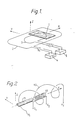
- FIGS 1 and 2 Elementary geometries of screened inductance transducer are illustrated in Figures 1 and 2, in each case showing a screen 1,11 respectively, a drive coil or winding 2,12, which in operation is normally excited by an oscillator, indicated schematically by reference 4 in Figure 1 only and a sense, or measurement, coil or winding 3,13.
- a signal processing means 5 adapted to receive signals from the sense winding 3 of the sensor and operate on them as required in order to provide a desired output, or outputs, which may be indicative of screen position, the rate of screen displacement relative to the sense winding, or both. While it is desirable that the screen 1,11 be physically interposed between the windings 2,3 or 12,13, this is not a necessary condition for operation.
- Transducer output from a screened inductance sensor is essentially an amplitude modulated carrier frequency.
- the carrier component is normally removed in a first stage of signal processing by synchronous demodulation.
- the transfer function relating the input variable to signal magnitude is the most important characteristic of any position measuring device.
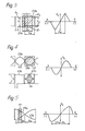
- the transducer's transfer function is related to the shapes of the sense windings 3,13 and the screens 1,11. Clearly an infinity of combinations are possible. but in practice these can be reduced to a small number of categories. The three most important of these categories and their respective outputs are illustrated in Figures 3, 4 and 5, while an overview of screened inductance sensor classification is given in subsequent Figure 6.
- All of the sense windings shown are composed of alternate turns of clockwise and anti-clockwise phase, respectively 23a, 23b; 33a, 33b; 43a, 43b; and 53a, 53b, which is a technique used in most practical transducers. It eliminates a DC bias on the output which would otherwise be present.
- the arrangements of Figures 3 and 4 have a common feature in that the screen 21, 31, 41 and sense winding 23a, 23b; 33a, 33b; 43a, 43b pitches Ps and Pw respectively, are substantially equal.
- the rectangular sense winding or coil 23a, 23b and rectangular screen 21 of the Figure 3 configuration result in a piecewise linear modulation of the output, i.e. linear sections of alternate rising and falling slopes. The local proportionality between input and output results in simple signal processing in many situations.
- Drive winding means to create an even field distribution over the area of the sense winding 23a, 23b is assumed.
- the configuration of the device ensures that sense winding area is uncovered at a constant rate with screen position the rate abruptly reversing after the screen has reached the point of fully covering one of the sense coils of the winding.
- a certain amount of rounding of the peaks of the output waveforms is inevitable, as indicated in the output signal represented in Figure 3.
- good linearity is achievable over a substantial portion of the ramp waveform, with proper design.
- the Figure 4 arrangement in either of the two variants shown, provides a device with a sinusoidal transfer function, the modulation envelope being designed to be a sinusoidal function of screen position.
- the modulation envelope can be achieved with a rectangular screen 31 and shaped windings 33a, 33b or by a shaped screen 41 and rectangular windings 43a, 43b, or indeed by a shaping of both elements.
- screen area predominates over winding area, and therefore practical designs will tend to take the form of the rectangular screen and shaped coil.
- the end result in any case should be to ensure that the nett flux linkage of the sense winding varies in a sinusoidal manner with screen position.
- This final category is denoted as 'Elongated Working Stroke' and the screen 51 pitch P s is deliberately chosen to be considerably shorter than the sense winding 53a, 53b pitch P w .
- the sense windings 53a, 53b take the form of a pair of substantially triangular loops meeting at a common apex, and the screen pitch, Ps, is made significantly less than the winding pitch, Pw.
- the modulation envelope is normally determined by the shape of the sense winding, which characteristically will have the tapered form of Figure 5. While screening efficiency and hence achievable accuracy tends to be reduced in this configuration, this is not necessarily disadvantageous in the applications to which elongated working stroke designs are suited.
- the sense windings of screened inductance sensors may have a single turn, as in the schematic arrangements of Figures 3, 4 and 5, or a multi-turn configuration may be used.
- each sense winding or sense winding coil may have several conductors, all contained in a single slot, or each coil may consist of a distributed winding, to achieve special output characteristics and take account of dimensional characteristics.
- sensitivity is increased by a multi-turn arrangement.
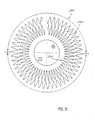
- a distributed multi-turn winding of generally sinusoidal configuration and comparable with the upper single-turn arrangement of Figure 4, is shown in Figure 6.
- the coil has the form of an array of elongate concentric curvilinear turns, the longer axis of each of which is aligned with the direction of relative displacement of the screen and secondary winding.
- the winding thus has a track 261 with a plurality of turns extending inwardly from start 262, to terminate in a central region of the winding at end 263.
- a similar outwardly extending track is provided on the opposite side of a single circuit board, for symmetry, and to cancel the effect of cross-overs.
- FIG. 7 An alternative layout of distributed winding is shown in Figure 7, in which an array 271 of displaced turns is provided, extending between start 272 and winding end 273. Each turn 271a, 271b, 271c and 271d is of the same size and shape, and the winding is laid out on a multi-wrap thin flexible substrate 274. While less economical in its use of space, a winding of this kind has an inherent ability to reduce harmonic content in the demodulated output wave. The design of a winding of this kind may also be achieved with a lesser number of iterations.
- Sinusoidal modulation may be achieved by a shaped double-tapered screen co-operating with a constant density solenoidal sense winding. or alternatively, a cylindrical screen of constant cross-section may be employed in conjunction with a solenoidal sense winding in which the lineal turn density varies sinusoidally.
- a solenoidal elongated working stroke configuration with a cylindrical screen and sense winding may also be provided.
- screened inductance sensors represent preferred embodiments of the screened inductance principle in which it is important for the drive field to have a substantially even distribution over the area of the sense winding in the absence of the screen, at least on the axis of motion.
- the drive field should have a constant value along any line in or parallel to the direction of relative screen and sense winding displacement, although it may vary at right angles to the direction of motion, so that the field density on any given such line is not necessarily the same as that along another and parallel line.
- Figure 9 shows the overall level measurement system, including a fuel tank 64 with a rotary sensor 61 and ballcock 62, 63 arrangement.
- the fuel level is deduced from the angle of the float arm 63.
- the screened inductance sensor offers the possibility of brushless operation and intrinsic safety, as will be shown.
- the device may also be designed to have a complementary transfer function, (arc Cos), to give an overall linearisation of system response.
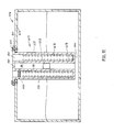
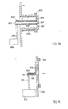
- a practical construction of the transducer 61 of Figure 9 takes the form shown in Figure 10.
- a stator 71 containing drive 72 and sense 73 windings is attached to the outer side of wall 74 of the tank 64, to overlie and externally occlude and seal off aperture or bore 86 in wall 74, while a rotor-float assembly 75 including a screen 76 arm 63 and float 62 pivots around a central stator shaft or axis 77, inside the tank 64.
- Pivot pin or axis 77 extends into the interior of the tank 64, through aperture 86, from external stator 71.
- Shaft 77 may be integral with stator 71.
- the barrier-defining stator 71 covers over the hole 86 in a sealing manner on the exterior of the tank while the rotor-float assembly is pivotably secured to shaft or spigot 77 so that it is disposed within the tank.
- Shaft or spigot 77 is a rigid component preferably integral with stator 71 and rotor-float assembly pivots about spigot 77 in operation of the unit. There is no physical transmission of rotor-float assembly 78 motion to those parts of the unit external of the tank.
- the stator 71 includes a supporting cylinder or spool portion 78 for a solenoidal drive winding 72.
- the sense windings 73 are laid out on a disc, which is contained within the stator unit radially inwardly of the drive winding. This sense winding disc 73 may typically be manufactured by printed circuit techniques.
- a ferrite flux return cup can optionally also be used. This may be covered by, or replaced with, a simple plastic or aluminium cover 79.
- Figures 11 and 12 show, respectively, an end or front and a sectional view of the transducer of Figures 9 and 10, the sectioned view of Figure 12 being substantially on the line XII-XII of Figure 11.
- this embodiment of transducer 91 is mounted on a tank 94 and has a float 92 with a lever arm 93.
- the stator 101 is of generally top-hat configuration with a flange portion fastened to the wall 104 of tank 94 by screws 111. Suitable sealing means is provided between the inner side of the flange and the outer side of wall 104.
- Drive winding 102 is a cylindrical coil of short axial length and is mounted on the exterior of the cylindrical portion of stator 101, near its end remote from tank wall 104.
- Sense winding 103 is laid on the remaining axially extending region of surface 108, between the outwardly disposed drive winding 102 and the f]ange of the top-hat section stator 101.
- Rotor assembly 105 carries the cylindrically segmental screen 106.
- the entire rotor assembly 105 and screen 106 are rotationally displaceable about an axis defined by a spindle 107 extending inwardly into the tank from the interior of the outer closed-off end of the top-hat section stator 101.
- the screen and the various other portions of the device which are located within the region containing the liquid, the level of which is to be measured, are physically separated from the remainder of the device, and in particular from the drive 102 and sense 103 windings, by means of a physical barrier defined by stator 101.
- stator 101 Apart from the use of a rotational cylindrical geometry in place of the planar rotational configuration of the earlier embodiment, the arrangement of Figures 13 and 14 differs from that of Figures 10, 11 and 12 in that the liquid enters into the space within the top-hat form sensor housing or stator 101. Again however, there is no physical communication or link between the liquid-immersed interior and the winding-equipped exterior of the unit.
- Linear transducers can also be used as level transducers although their larger size may render them less advantageous.
- Figures 15 and 16 show a planar configuration of level gauge, Figure 15 in front view and Figure 16 in section on the plane XVI-XVI of Figure 15, while Figure 17 shows a cylindrical type.
- Operation of the device is again substantially equivalent in electrical terms to that of the rotary planar and rotary cylindrical devices already described, and a configuration in which the screen assembly is physically sealed off from the remainder of the device is again provided, by virtue of the sealing engagement of stator plate 131 against wall 134 of tank 124.
- the device is oriented on tank 154 so that its longitudinal axis extends in a substantially vertical direction.
- a float 152 consisting of a hollow cylinder of copper or aluminium moves upwardly and downwardly within the inner tube 178.
- a vent aperture 185 communicates between the interior 186 of the central tube 178 and the exterior of the outer tube portion 179 to vent air from within the inner tube 178 during float displacement.
- the drive 162 and sense 163 windings are generally solenoidal and concentric and are located within the annular space 183 between the inner 178 and outer 179 tube portions of stator 161. Operation of the device is again electrically in line with that of the arrangements already described and also as set out in co-pending patent applications directed to other variants of screened inductance sensor.
- the screen of the device defined by float 152, is physically separated from the remainder thereof by a barrier defined by the two-part convoluted tubular stator 161.
- the senor of the invention is provided as an integral unit, for mounting over an opening cut in the wall of the tank in sealing engagement with the wall around the periphery of the opening.
- the sensor of the invention is adapted for application to an integral tank wall uninterrupted by any opening or aperture.
- Tank wall 294 is provided with an outwardly directed deformed region or "dimple" 306, of generally cylindrical configuration and closed off at its outer end by disc-shaped wall portion 299. Such a deformed region may readily be formed during production of the tank or tank wall, especially in the case of a tank moulded from plastics material.
- Cylindrical or annular drive 292 and sense 293 windings are mounted on the exterior of portion 306.
- a central spigot or shaft 297 affixed to end wall region 299 or formed integrally therewith extends along and through the cylindrical space bounded by wall portion 306 to and into the main liquid-containing region of the tank.
- a rotor/float assembly sleeve 295 is retained on shaft 297 for rotation relative thereto by an end cap or screw 303.
- Cylindrically-sectoral form screen 296 is attached to, mounted on, or formed integrally with sleeve 295.
- Float arm 283 extends radially from the tank space end of sleeve 295 and terminates at float 282. Operation of the device is as already described for Figures 13 and 14.
- FIG 19 shows a configuration similar in general concept to that of Figure 18, but of planar construction and broadly equivalent to the demountable unitary embodiment of Figures 10, 11 and 12.
- Tank wall 324 is uninterrupted by either apertures or deformations.
- Drive 322 and sense 323 windings are affixed to the exterior of the wall portion 324, drive winding 322 being a ring-shaped coil and sense winding 323 of a flat printed circuit disc-shaped configuration to be described.
- Coaxially with windings 322 and 323, spigot 327 extends inwardly from the inner surface of wall portion 324, to which it is affixed or otherwise secured, or with which it may be integrally formed.
- screened inductance transducers can be designed to have any arbitrary transfer function relating the output to input.
- Three principal categories have been identified - piecewise-linear, sinusoidal and elongated working stroke. The latter category - elongated working stroke, where the screen pitch is shorter then the sense winding pitch - is generally advantageous for limited motion applications such as the level measurements described. However, for other barrier-type sensor applications where rotation is continuous or where linear motion is measured with multi-cycle transducers, other categories may be appropriate.
- a drive field is established by the single drive winding which is substantially even in the direction of motion of the screen relative to the sense windings.
- the sensor is thus largely immune to field variation across the axis of motion. It is however necessary for the drive field to have this substantially even or uniform distribution over the extent of the sense winding, in the absence of the screen, at least along individual paths swept out by points on the screen in the course of their normal motion, although a wholly uniform field distribution over the entire extent of the sense winding is not essential.
- Even field distribution in this sense also facilitates design of a screened inductance sensor for any given application.
- equations (1) and (2) above assume even field.
- This program takes outline winding dimensions as inputs, and produces layouts for final PCB artworks as outputs.
- the calculation of the winding shape is performed in two stages. Firstly, the winding shape is calculated for a planar two-pole geometry and, secondly, this shape is transformed to a rotary geometry with the correct number of poles.
- a linear transfer function i.e. linear modulation
- the calculation procedure is substantially independent of modulation type.
- the basic equation describing the winding pattern is input into the design system (i.e. the computer) by the designer, and typically comes from a mixture of theory (as above), intuition and experience.
- Exemplary equation (4) provides a particular modulation envelope and other equations are used for different modulation envelopes (i.e. different transducer functions).
- dA d1 KP , constant (6) where P is the screen span or pitch in the direction of displacement, ( Figure 20).
- This function is constant, and since according to equation (2), it is the slope of the modulation envelope, there is therefore linear modulation, i.e. the transfer function is linear,
- multi-turn windings such as the concentric-shaped winding shown in Figure 21, are required.
- w′(x) may be defined as the sum of the coil widths, y l through y n , where n is the number of turns at any value of x Figure 21, and is thus the rate of change of total coil area with x.
- This function must also follow equation (4) to give linear modulation.
- the winding shape must be defined by the following equation This function must have the same form as equation (4) to give linear modulation.
- the winding shape may be defined by the following equation:
- This equation has an infinite number of solutions for y i .
- the above equations may be satisified by an infinite set of "y" values, and therefore some extra constraints must be imposed in order to obtain a solution.
- the first and mandatory constraint comes from the overall winding dimensions and is the maximum winding height, ⁇ as shown in Figure 21. This effectively sets the value of "y l ".
- the second and arbitrary constraint normally imposed is a constant spacing, s, between coils, an obvious choice for printed circuit windings. Alternatively, the spacing may vary over winding height or width, i.e. its dimension in the y direction.
- a final constraint is the total number of coils, N, which for obvious practical reasons is limited by the ratio of y to s, but is otherwise selectively variable within this upper limit.
- n which as seen in Figure 21, is also a function of x.
- This function is defined by N break points b i , at each of which the y value reaches zero and n increases by 1.
- Equation (11) is used to calculate the constant K in winding shape function w′(x).
- equation (12) there is an iterative search for N break points using equation (13).
- a set of y l values is calculated for a range of x values using equations (9) and (12), thus completely defining the winding shape for the first quadrant, Figure 21.
- the winding shapes for the remaining three quadrants are derived by reflection of the first quadrant shape for the linear planar phase of the design procedure.
- the second stage of calculation is the transformation from linear to rotary geometry. This involves mapping the x axis to a circle of radius r ( Figure 22) equal to the mean winding radius and the y axis to a radius, as illustrated in Figure 22.
- the basic linear pattern or layout is initially transformed to polar coordinates, and the complete multi-turn coil pattern as thus transformed is then laid out at a plurality of rotationally displaced locations by further rotational displacement or transformation of the basic pattern to each successive such location.
- Each location corresponds to a specified predetermined angle of further rotation of the basic layout in toto.
- the program not only plots the final artwork, but allows the user to examine the winding in detail and make changes, if required, before the final plotting.
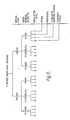
- FIG 23 A block diagram of the program is shown in Figure 23.
- the program is made up of a number of modules. various combinations of which are used depending on the desired winding type.
- the first stage, Data Entry is universal for all windings and is used to edit winding and circuit board dimensions.
- a typical menu for this stage is shown in Figure 24. To change any set of parameters, the appropriate line number is typed in and followed by new parameters.
- the basic winding shape for two pole planar linear geometry is calculated.
- a number of options are available depending on the modulation type. For the foregoing example, linear modulation would be chosen. However, it is possible to obtain any form of modulation by defining the appropriate function for w′(x). For example, some of the boards of a device in accordance with the invention may have a sinusoidal modulation function to make the device suitable for use with resolver to digital converters in which case the choice of function for w′ (x) is Sin ⁇ . If linearization of the measurement system transfer function is required, the choice for w′(x) is then Arc Cos ( ⁇ ).
- the winding shape is transformed to, for example. radial co-ordinates.
- the winding crossovers and interconnecting tracks and pads are defined. Again, a number of options are available depending on modulation type and interconnection strategy.
- the Plotting Stage there are three possible output formats: Graphics Screen, a Pen Plot or a Photoplot file.
- the output format is selected by the user while the running program, the graphics screen, is used to examine the artwork in detail, and the photoplot file is used to produce final circuit board artworks.
- a menu for the Graphics output or plotting menu is shown in Figure 25.
- Graphics plotting there is a zoom facility to examine any part of the winding in detail. Also the distance, in mm, between any two points on the screen can be displayed by means of a further facility to check pad and track clearances before final artwork plotting.
- a plotting menu facilitates viewing the full PCB artwork or just some parts of it, such as the interconnection tracks or the pads for the plated through holes.
- the program then produces an output file of movement or plotting commands for a Photoplotter.
- a particular advantage of this program is the speed with which new windings can be developed. It is possible to introduce correction factors into the calculation stage to account for any experimentally-measured transducer non-linearities. Thus windings giving very accurate outputs can be developed in just a few design iterations, with an empirical correction factor being applied to the function defining w′(x), derived, for example, from construction and testing of one or more prototype windings. Finally, it is possible to implement almost any transfer function to account for measurement system non-linearities and thus simplify the overall system.
- the screen and sense winding Printed Circuit Board are, in effect, the heart of the transducer. Their design is the primary determining factor for the accuracy of the output modulation envelope. The advantages of working with printed circuit techniques are striking:-
- the software Given the expression for the modulation envelope, the software will calculate the correct winding pattern.
- the accuracy specification for transducers according to the invention may be defined in terms of arc minutes maximum error. This is quite comparable with what is typically achieved from frameless resolvers of the same size. What is quite remarkable is that an accuracy of typically 1 part in 3000 can be achieved from such a simple device.
- devices in accordance with the invention may be designed to avoid the need for tight tolerances in mounting dimensions. This may be combined with a simple frameless mounting method and short axial length to greatly facilitate their incorporation within equipment.
- the ability to use injection moulded plastic parts throughout greatly facilitates low cost volume manufacture.
- the repeatability of the printed circuit windings and injection moulded parts opens the possibility of totally automated manufacture.
- the ease with which design equations can be translated from a computer keyboard into hardware makes the system of the invention truly of its time.
- a further refinement enables crowding of the turns to be avoided, especially at the coil ends.
- the spacing "s" between turns is constant, this resulting in potentially excessively close coming together of turns at the ends of the winding.
- the polar transformation depicted in Figure 22 incorporated such variable track and break point spacing at the linear planar stage, resulting in the significantly enhanced or increased turn spacing or more spread out configuration evident in the finally transformed pattern of this Figure.
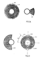
- Figure 26 shows one side of a typical double-sided printed circuit board 191 produced by the process described herein, together with an associated screen 199.
- the board and screen of Figure 26 are designed for elongated working stroke output.
- Figure 27 shows one side of a similar board 201 and screen 209 pair for sinusoidal output.
- Figure 28 shows one side of a board 211 which gives piecewise linear modulation. The track spacing between the coils is selected in each case to be the minimum possible consistent with ease of PCB manufacture.
- a useful practical technique for ensuring correct registration of the printed circuit board within a transducer is also shown.
- each board of these and subsequent Figures is provided with complementary printed circuit windings on each side of the board so that the effects of crossovers are cancelled out, as previously described.
- the copper track of the printed circuit board should have its central axis coincident with the centre axis of the transducer as a whole.
- One alignment procedure is to locate the board by engagement of its outer diameter within a mating annular spigot in the transducer.
- the manufacturing processes for printed circuit boards do not necessarily lend themselves to the maintenance of tight tolerances between track pattern and the outer dimensions of the board. Close tolerances may however more readily maintained between a track pattern and holes drilled in the board. The finished printed circuit boards may then be precisely located within the transducers by pins engaging in and passing through these drilled holes.
- These aligning holes may be either full holes, or they may be half holes generally aligned with an outer diameter of a circular printed board. Such half holes may be initially drilled as full holes, and the surplus peripheral region of the board subsequently cut away.
- the transducer may be designed so that the outer periphery or diameter of the printed circuit board is clear of any contact with any other element of the transducer unit, other than at the alignment holes and their mating pins, which provide location of the board.
- Figure 26 shows a circular printed circuit board 191, having half circular alignment holes 192 at opposite ends of a diameter of the board.
- the holes may be drilled for alignment with pins located on a 45° axis so that the inversion of one printed circuit board relative to the other will achieve correct relative alignment of the boards for electrical quadrature.
- Figure 27 shows an arrangement of this kind, in which board 201 has full holes 202 located on one diameter and half holes 203 located on a second diameter, displaced by 45° from the first diameter, on which holes 202 are located.
- printed circuit board 211 has peripheral half-hole centres identified by references 212 and carries a sensor winding 214 shaped to give piecewise linear modulation.
- the sense winding coils 214a and 214b are equivalent in rotary planar terms to the rectangular coils of the simplified planar representation of Figure 3.
- the double-sided board with two PCWs in back-to-back disposition ensures cancellation of any cross-over type effects, and this balance also extends to the innermost reverse link 214c of Figure 28.
- Two circuit boards of the kind shown in, for example, Figure 27 may be used to give outputs in phase quadrature.
- the two printed circuit boards are mounted in quadrature.
- two quadrature phases can be laid on one PCB, such as is illustrated in Figure 29, and each phase winding is formed by series combination of one winding from each of the two boards.
- the advantage is substantial reduction in quadrature error due to quadrature misalignment of boards.
- Figure 29 shows a single-board arrangement with two quadrature windings 224, 225 laid on a single PCB 221 at different mean diameters.
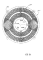
- Figure 30 shows a similar arrangement for a multipole transducer in which board 231 has a multiplicity of windings 234, 235, an outer series of coils 234 being on a first mean diameter and a second or inner series of coils 235 being laid out along a path of a second mean diameter less than that of the circumferential locus on which coils 234 are disposed.
- the advantages of this single-board arrangement became more significant at the higher number of poles, because any mechanical quadrature misalignment between phases results in an electrical misalignment multiplied by half the number of poles.
- Figure 31 shows one side of a winding configuration for a double-sided PCB for a 100 pole transducer board 241 carrying outer 244 and inner 245 sense windings.
- single turn sinusoidally shaped windings are used in each case, because of space limitations on the board.
- the winding shown in Figure 32 has two quadrature windings 254, 255 on a single PCB, each winding 254 and 255 having the same mean diameter. Alternate sets of coil pairs are connected in series to form the two phase windings. Thus, for example, coil pairs 254a and 254b define a portion of a first phase winding, while coil pairs 255a and 255b define a portion of a second phase winding. This winding is most useful for large diameter multicycle transducers. It has the advantages of having perfect quadrature and magnitude matching between phases.
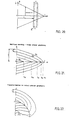
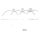
- Figures 33 to 39 relate to winding configurations which permit displaced-turn multi-turn distributed windings of the kind described in regard to Figure 7 to be realized by similar economical printed-circuit (P.C.) techniques likewise adapted to computer design and artwork layout. They are described in the context of "Resolver Lookalikes" having sine and cosine target waveforms. These winding arrangements are described in regard to rotary planar configurations of sense winding.
- P.C. printed-circuit
- the basic winding element of a screened inductive position or speed sensor in many configurations is a "figure-of-eight" shaped coil. Distributing a number of coils of this shape by coil displacement rather than by a "concentric" layout results in a large number of crossovers, creating difficulties for printed-circuit realization. Displaced-turn distributed windings may, of course, be provided by various "labour-intensive” techniques, e.g., by forming grooves into which the winding wire is pressed. It may however be difficult to assure consistent results at low cost by such a method.
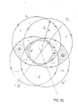
- FIG. 33 In the idealized schematically represented distributed winding of Figure 33.
- four circular (or near-circular) coils a, a′ and b, b′ are provided, for a planar rotary device printed circuit board having a central aperture denoted by "O".
- Coils a, a′ constitute a basic "figure of eight" contra-connected pair designed to exhibit an approximately sinusoidal flux-linkage variation with angle.
- Coils b, b′ constitute an identical pair displaced clockwise by 60 degrees. In this elementary displaced-turn distributed winding, the turns are connected in series in a threading sense shown by the arrows.
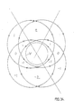
- Figure 34 shows such an equivalent winding scheme which has only two crossovers, and these are confined to the exiting leads, as compared with the twelve crossovers of Figure 33.
- the winding of Figure 34 provides a winding akin to the "concentric" type winding of Figure 6 and others of the Figures, but is equivalent to the displaced-turn distributed winding of Figure 33.
- the direction of notional current flow in the various segments of this equivalent winding is indicated in Figure 34, and it will be seen that the notional current patterns of Figures 33 and 34 are identical.
- the two windings are equivalent in electromagnetic terms.
- the intercept "x" along a radius extending from the centre of the disc on which the winding is laid, which coincides with the axis of rotation of the sensor should vary in sinusoidal manner with circumferential displacement, i.e. movement in the direction of the screen/winding displacement.
- this desired sinusoidal modulation may be approximate, and in a practical arrangement, a more precise coil shaping may be appropriate.
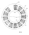
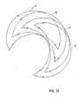
- Figure 35 shows four crescent-moon shaped coils a, b, c, d, for a rotary planar screened inductance sensor circumferentially displaced in steps of 30°.
- the third harmonic is eliminated here, its phase shift between coils being 3 x 30° or 90°, so that its four phasors lie along the sides of a square.
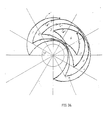
- four "concentric" coils a′, b′, c′, d′ of different pitches can be formed in series, resulting in the configuration shown in Figure 36, in which the crossovers of Figure 35 are eliminated for a printed circuit board with central aperture "O".
- Figure 37 shows how interpenetration of coils a′ b′ c′, d′ of Figure 36 with four complementary counter-clockwise crescents a ⁇ , b ⁇ , c ⁇ , and d ⁇ can be accomodated by further reshaping in the region of the "horns" of the crescent, where, in the configuration of Figure 37, the coil extremities extend across the diameter delimiting one boundary of the generally semi-circular region within which the crescent coils are located.
- the numbers in the meshes denote the appropriate nett linkage, and these are effected using "concentric" coils.
- the coils have a peculiar toothed appearance, but no coils project across the axis of symmetry EE dividing the clockwise coils from the anti-clockwise coils.
- Comparison of the notional current directions indicated for each winding in Figures 35, 36, and 37 shows that on the equivalent winding of Figure 37 the notional current pattern is identical with that of Figure 36, so that the broadly "concentric” distributed winding of Figure 37 is again equivalent to the "displaced-turn” distributing windings of Figures 35 and 36.
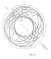
- Figure 38 shows an alternative arrangement in which the crescent inner profiles are concentric with the machine axis.
- a short jumper connection at JJ places the coils a and d in series.
- the rotating flux screen should extend radially to cover this jumper connection.
- the corresponding portions of an entirely symmetric set of coils may be similarly placed in series by a corresponding jumper.
- the terminals TT serve the entire winding on the PCB, central aperture "O" being also indicated. More highly distributed windings than those shown in the present drawings may also be used.
Landscapes
- Engineering & Computer Science (AREA)
- Power Engineering (AREA)
- Physics & Mathematics (AREA)
- General Physics & Mathematics (AREA)
- Manufacturing & Machinery (AREA)
- Fluid Mechanics (AREA)
- Microelectronics & Electronic Packaging (AREA)
- Measurement Of Length, Angles, Or The Like Using Electric Or Magnetic Means (AREA)
- Transmission And Conversion Of Sensor Element Output (AREA)
- Level Indicators Using A Float (AREA)
- Measurement Of Levels Of Liquids Or Fluent Solid Materials (AREA)
Applications Claiming Priority (4)
| Application Number | Priority Date | Filing Date | Title |
|---|---|---|---|
| IE157687 | 1987-06-15 | ||
| IE157687 | 1987-06-15 | ||
| IE157587 | 1987-06-15 | ||
| IE157587A IE871575L (en) | 1987-06-15 | 1987-06-15 | Improvements in or relating to printed circuit windings for¹screened inductance sensors |
Publications (2)
| Publication Number | Publication Date |
|---|---|
| EP0295609A2 true EP0295609A2 (fr) | 1988-12-21 |
| EP0295609A3 EP0295609A3 (fr) | 1991-01-09 |
Family
ID=26319126
Family Applications (1)
| Application Number | Title | Priority Date | Filing Date |
|---|---|---|---|
| EP19880109385 Withdrawn EP0295609A3 (fr) | 1987-06-15 | 1988-06-13 | Bobinages de circuits imprimés par capteurs d'induction blindés, notamment capteurs de la mesure de niveau |
Country Status (3)
| Country | Link |
|---|---|
| US (1) | US4986124A (fr) |
| EP (1) | EP0295609A3 (fr) |
| JP (1) | JP2740786B2 (fr) |
Cited By (8)
| Publication number | Priority date | Publication date | Assignee | Title |
|---|---|---|---|---|
| WO2000077480A3 (fr) * | 1999-06-15 | 2001-02-08 | Scient Generics Ltd | Codeur de position |
| US7222530B2 (en) | 2004-05-07 | 2007-05-29 | Yazaki Corporation | Non-contact type liquid level sensor and non-contact type liquid level detecting method |
| US7331225B2 (en) | 2004-05-07 | 2008-02-19 | Yazaki Corporation | Non-contact type liquid level sensor |
| EP1975570A2 (fr) | 2007-03-30 | 2008-10-01 | Cherry GmbH | Elément d'actionnement à courant de Foucault inductif et procédé de fabrication d'un élément d'amortissement inductif |
| DE102005039881B4 (de) * | 2004-08-24 | 2012-12-27 | Aisin Aw Co., Ltd. | Resolver |
| EP2728319A3 (fr) * | 2012-11-01 | 2015-01-07 | TI Group Automotive Systems, L.L.C. | Jauge de niveau de liquide sans contact |
| US20150369648A1 (en) * | 2014-06-23 | 2015-12-24 | Medallion Instrumentation Systems, Llc | Fluid level sensor |
| CN112185686A (zh) * | 2020-09-22 | 2021-01-05 | 中车株洲电机有限公司 | 绕向交替连续式线圈绕制装置及方法 |
Families Citing this family (23)
| Publication number | Priority date | Publication date | Assignee | Title |
|---|---|---|---|---|
| US5406155A (en) * | 1992-06-03 | 1995-04-11 | Trw Inc. | Method and apparatus for sensing relative position between two relatively rotatable members |
| EP0743508A2 (fr) * | 1995-05-16 | 1996-11-20 | Mitutoyo Corporation | Capteur de position employant un courant d'induction |
| US6003966A (en) * | 1997-02-28 | 1999-12-21 | Samsung Electronics Co., Ltd. | Device for sensing cartridge replacement time in a printer equipment using an inkjet injecting apparatus |
| US6089086A (en) * | 1997-08-26 | 2000-07-18 | Rochester Gauges, Inc. | Liquid level gauge |
| US6453741B1 (en) * | 1999-08-26 | 2002-09-24 | International Avionics, Inc. | Fuel transmitter for non-electrically invasive liquid level measurement |
| US6304076B1 (en) | 1999-09-07 | 2001-10-16 | Bei Sensors & Systems Company, Inc. | Angular position sensor with inductive attenuating coupler |
| JP3605097B2 (ja) * | 2002-07-02 | 2004-12-22 | 矢崎総業株式会社 | 非接触式液面レベルセンサ |
| US7797661B2 (en) * | 2004-09-03 | 2010-09-14 | Abb Research Ag | Method and apparatus for describing and managing properties of a transformer coil |
| US7263672B2 (en) * | 2004-09-03 | 2007-08-28 | Abb Research Ltd. | Methods, systems, and data models for describing an electrical device |
| US7023363B1 (en) * | 2005-02-17 | 2006-04-04 | Saiful Bahari Saidan | Position encoding using impedance comparison |
| US7721241B2 (en) * | 2005-07-29 | 2010-05-18 | Abb Research Ltd. | Automated method and tool for documenting a transformer design |
| US7621182B2 (en) * | 2007-04-09 | 2009-11-24 | Jack Chen | Sealed fuel level detector |
| JP5224830B2 (ja) * | 2008-01-18 | 2013-07-03 | 株式会社ミツトヨ | 電磁誘導式エンコーダ |
| US8098061B2 (en) * | 2008-04-15 | 2012-01-17 | Ksr Technologies Co. | Linear inductive position sensor |
| WO2016029204A1 (fr) * | 2014-08-22 | 2016-02-25 | Ksr Ip Holdings Llc. | Capteur inductif |
| MX380917B (es) * | 2015-02-18 | 2025-03-12 | Ti Group Automotive Systems Llc | Transmisor de nivel. |
| DE102015011172A1 (de) * | 2015-09-01 | 2017-03-02 | Baumer Electric Ag | Elektronischer Winkelsensor für Zeigerinstrumente |
| DE102016118266A1 (de) * | 2016-09-27 | 2018-03-29 | Methode Electronics Malta Ltd. | Kontaktloser Fluidpegelsensor |
| KR20200035054A (ko) * | 2017-08-21 | 2020-04-01 | 케이에스알 아이피 홀딩스 엘엘씨. | 중심 신호 프로세서를 가지는 유도형 센서 모듈 조립체 |
| JP7533473B2 (ja) * | 2019-10-24 | 2024-08-14 | 日本精機株式会社 | 位置検出装置及び液面検出装置 |
| EP3885711B1 (fr) * | 2020-03-25 | 2023-03-01 | Melexis Technologies SA | Capteur de position inductif |
| US20230075841A1 (en) * | 2021-09-09 | 2023-03-09 | State Farm Mutual Automobile Insurance Company | Continuous water level monitoring for sump pump system control |
| US12244183B2 (en) | 2021-09-21 | 2025-03-04 | Advanced Automation Group | Angle sensor device |
Family Cites Families (26)
| Publication number | Priority date | Publication date | Assignee | Title |
|---|---|---|---|---|
| US2424766A (en) * | 1944-06-19 | 1947-07-29 | Builders Iron Foundry | Telemetric apparatus |
| US2629004A (en) * | 1947-06-10 | 1953-02-17 | Maurice L Greenough | Electrical micrometer |
| GB811417A (en) * | 1957-07-16 | 1959-04-02 | Gen Electric Co Ltd | Improvements in or relating to liquid level indicators |
| FR1187962A (fr) * | 1957-11-13 | 1959-09-17 | Electronique & Automatisme Sa | Variomètres |
| US3491289A (en) * | 1968-12-17 | 1970-01-20 | Atomic Energy Commission | Non-contact eddy current instrument |
| US3588687A (en) * | 1969-11-18 | 1971-06-28 | Us Army | Sensing coil arrangement for a metal detector |
| US3717835A (en) * | 1970-02-24 | 1973-02-20 | W Roadstrum | Electrical coil |
| US3772587A (en) * | 1972-03-15 | 1973-11-13 | Inductosyn Corp | Position measuring transformer |
| GB1479325A (en) * | 1973-10-05 | 1977-07-13 | Commissariat Energie Atomique | Measurement of level of paramagnetic liquids |
| JPS5441183B2 (fr) * | 1973-12-01 | 1979-12-07 | ||
| US4123735A (en) * | 1975-02-25 | 1978-10-31 | Mash Dmitry M | Induction-type meter for measuring mechanical quantities |
| US4006637A (en) * | 1975-05-16 | 1977-02-08 | Yohei Kinosita | Electro-mechanical displacement transducer |
| US4042876A (en) * | 1976-04-29 | 1977-08-16 | The United States Of America As Represented By The United States Energy Research And Development Administration | Eddy current gauge for monitoring displacement using printed circuit coil |
| US4164706A (en) * | 1976-10-18 | 1979-08-14 | Nippon Soken, Inc. | Rotational position detector utilizing an FET blocking oscillator |
| SE406642B (sv) * | 1977-02-16 | 1979-02-19 | Aga Ab | Elektromekanisk legesgivare |
| US4210865A (en) * | 1977-12-12 | 1980-07-01 | Chaika Leopold I | Position sensor of linearly moving bodies |
| US4580096A (en) * | 1981-07-06 | 1986-04-01 | Coulter Electronics, Inc. | Isotachophoresis analyzer for inductively detecting boundaries between adjoining substances having different conductivities |
| JPS5811864A (ja) * | 1981-07-15 | 1983-01-22 | Yokogawa Hokushin Electric Corp | 渦電流式検出部の位置測定方法 |
| SU1062512A1 (ru) * | 1982-03-23 | 1983-12-23 | Yalov Grigorij N | Способ определени остаточных напр жений в объектах из неоднородных по структуре материалов |
| US4447743A (en) * | 1982-04-28 | 1984-05-08 | The United States Of America As Represented By The United States Department Of Energy | High pressure liquid level monitor |
| JPS59166801A (ja) * | 1983-03-09 | 1984-09-20 | Nippon Kokan Kk <Nkk> | 渦電流を利用した差動帰還型距離測定装置 |
| US4717874A (en) * | 1984-02-10 | 1988-01-05 | Kabushiki Kaisha Sg | Reluctance type linear position detection device |
| US4627280A (en) * | 1984-04-24 | 1986-12-09 | Toyoda Gosei Co., Ltd. | Inductance liquid level meter |
| IE55855B1 (en) * | 1984-10-19 | 1991-01-30 | Kollmorgen Ireland Ltd | Position and speed sensors |
| US4723446A (en) * | 1985-04-04 | 1988-02-09 | Kanto Seiki Co., Ltd. | Device for measuring displacement |
| IE871008L (en) | 1987-04-16 | 1988-10-16 | Kollmorgen Ireland Ltd | Screened inductance sensors |
-
1988
- 1988-06-13 EP EP19880109385 patent/EP0295609A3/fr not_active Withdrawn
- 1988-06-15 JP JP63147915A patent/JP2740786B2/ja not_active Expired - Lifetime
- 1988-06-15 US US07/207,384 patent/US4986124A/en not_active Expired - Lifetime
Cited By (14)
| Publication number | Priority date | Publication date | Assignee | Title |
|---|---|---|---|---|
| GB2359139A (en) * | 1999-06-15 | 2001-08-15 | Scient Generics Ltd | Position encoder |
| US6561022B1 (en) | 1999-06-15 | 2003-05-13 | Scientific Generics Limited | Position encoder |
| GB2359139B (en) * | 1999-06-15 | 2003-09-03 | Scient Generics Ltd | Position encoder |
| WO2000077480A3 (fr) * | 1999-06-15 | 2001-02-08 | Scient Generics Ltd | Codeur de position |
| DE102005021314B4 (de) * | 2004-05-07 | 2010-07-29 | Yazaki Corp. | Füllstandssensor |
| US7222530B2 (en) | 2004-05-07 | 2007-05-29 | Yazaki Corporation | Non-contact type liquid level sensor and non-contact type liquid level detecting method |
| US7331225B2 (en) | 2004-05-07 | 2008-02-19 | Yazaki Corporation | Non-contact type liquid level sensor |
| DE102005039881B4 (de) * | 2004-08-24 | 2012-12-27 | Aisin Aw Co., Ltd. | Resolver |
| EP1975570A3 (fr) * | 2007-03-30 | 2012-11-07 | ZF Friedrichshafen AG | Elément d'actionnement à courant de Foucault inductif et procédé de fabrication d'un élément d'amortissement inductif |
| EP1975570A2 (fr) | 2007-03-30 | 2008-10-01 | Cherry GmbH | Elément d'actionnement à courant de Foucault inductif et procédé de fabrication d'un élément d'amortissement inductif |
| EP2728319A3 (fr) * | 2012-11-01 | 2015-01-07 | TI Group Automotive Systems, L.L.C. | Jauge de niveau de liquide sans contact |
| US20150369648A1 (en) * | 2014-06-23 | 2015-12-24 | Medallion Instrumentation Systems, Llc | Fluid level sensor |
| CN112185686A (zh) * | 2020-09-22 | 2021-01-05 | 中车株洲电机有限公司 | 绕向交替连续式线圈绕制装置及方法 |
| CN112185686B (zh) * | 2020-09-22 | 2022-06-21 | 中车株洲电机有限公司 | 绕向交替连续式线圈绕制装置及方法 |
Also Published As
| Publication number | Publication date |
|---|---|
| EP0295609A3 (fr) | 1991-01-09 |
| JPS6488121A (en) | 1989-04-03 |
| JP2740786B2 (ja) | 1998-04-15 |
| US4986124A (en) | 1991-01-22 |
Similar Documents
| Publication | Publication Date | Title |
|---|---|---|
| US4986124A (en) | Screened inductance sensors, especially sensors for level measurement | |
| US4853604A (en) | Position and speed sensors | |
| US9945653B2 (en) | Inductive position sensor | |
| US8020453B2 (en) | Inductive position sensor | |
| CN107407577B (zh) | 感应式移动传感器 | |
| CN103868535A (zh) | 电感式位置测量装置 | |
| JPH02502670A (ja) | 誘導変位センサ | |
| CN102822632A (zh) | 位置传感器 | |
| EP1898185A1 (fr) | Capteur de position | |
| US7932715B2 (en) | Inductive detector with variable width loops on first and second surfaces of substrate | |
| EP1828722B1 (fr) | Capteur de position inductive | |
| US20220231582A1 (en) | Angular displacement decoder and method of construction of the device | |
| Brasseur | A robust capacitive angular position sensor | |
| HK1245390B (zh) | 感应式移动传感器 | |
| EP3091339B1 (fr) | Capteur de rotation non volatile avec piste en spirale | |
| JPS61159101A (ja) | 位置および速度センサ | |
| US4887465A (en) | Transducers for hostile environments | |
| EP2080991A1 (fr) | Dispositif de détection d'angle de rotation | |
| EP1847800A1 (fr) | Capteur de rotation | |
| EP4467931A1 (fr) | Capteur de position rotatif | |
| CN113899298A (zh) | 一种基于相移正余弦双路电压检测的电感位置传感装置 | |
| EP1825225B1 (fr) | Detecteur inductif | |
| CN222353214U (zh) | 电感组件布置结构、角位移测量装置和线性位移测量装置 | |
| JP2005201855A (ja) | 誘導型変位検出装置及びマイクロメータ | |
| EP4367480A1 (fr) | Capteur de position de rotation |
Legal Events
| Date | Code | Title | Description |
|---|---|---|---|
| PUAI | Public reference made under article 153(3) epc to a published international application that has entered the european phase |
Free format text: ORIGINAL CODE: 0009012 |
|
| AK | Designated contracting states |
Kind code of ref document: A2 Designated state(s): CH DE FR GB IT LI NL SE |
|
| PUAL | Search report despatched |
Free format text: ORIGINAL CODE: 0009013 |
|
| AK | Designated contracting states |
Kind code of ref document: A3 Designated state(s): CH DE FR GB IT LI NL SE |
|
| 17P | Request for examination filed |
Effective date: 19910625 |
|
| 17Q | First examination report despatched |
Effective date: 19930827 |
|
| STAA | Information on the status of an ep patent application or granted ep patent |
Free format text: STATUS: THE APPLICATION IS DEEMED TO BE WITHDRAWN |
|
| 18D | Application deemed to be withdrawn |
Effective date: 19940715 |