EP0295682A2 - Dispositif d'enregistrement et de reproduction optique, sélectif pour la longueur d'onde - Google Patents
Dispositif d'enregistrement et de reproduction optique, sélectif pour la longueur d'onde Download PDFInfo
- Publication number
- EP0295682A2 EP0295682A2 EP88109653A EP88109653A EP0295682A2 EP 0295682 A2 EP0295682 A2 EP 0295682A2 EP 88109653 A EP88109653 A EP 88109653A EP 88109653 A EP88109653 A EP 88109653A EP 0295682 A2 EP0295682 A2 EP 0295682A2
- Authority
- EP
- European Patent Office
- Prior art keywords
- wavelength
- medium
- light source
- light
- output
- Prior art date
- Legal status (The legal status is an assumption and is not a legal conclusion. Google has not performed a legal analysis and makes no representation as to the accuracy of the status listed.)
- Granted
Links
Images


Classifications
-
- G—PHYSICS
- G11—INFORMATION STORAGE
- G11B—INFORMATION STORAGE BASED ON RELATIVE MOVEMENT BETWEEN RECORD CARRIER AND TRANSDUCER
- G11B7/00—Recording or reproducing by optical means, e.g. recording using a thermal beam of optical radiation by modifying optical properties or the physical structure, reproducing using an optical beam at lower power by sensing optical properties; Record carriers therefor
-
- G—PHYSICS
- G11—INFORMATION STORAGE
- G11B—INFORMATION STORAGE BASED ON RELATIVE MOVEMENT BETWEEN RECORD CARRIER AND TRANSDUCER
- G11B7/00—Recording or reproducing by optical means, e.g. recording using a thermal beam of optical radiation by modifying optical properties or the physical structure, reproducing using an optical beam at lower power by sensing optical properties; Record carriers therefor
- G11B7/004—Recording, reproducing or erasing methods; Read, write or erase circuits therefor
- G11B7/0045—Recording
- G11B7/00453—Recording involving spectral or photochemical hole burning
Definitions
- the present invention relates to a wavelength selective optical recording and reproducing device.
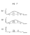
- Fig. 6 shows a construction of a conventional such device which is disclosed in Japanese Patent Publication Gazette No. 51355/1983 and Fig. 7 illustrates wavelength spectrum of a recording medium having information recorded.
- a reference numeral 10 depicts a wavelength variable light source such as semiconductor laser, 11 a controller for varying wavelength of the light source 10, 12 a collimating lens for making light from the light source 10 parallel beam, 13 a deflector, 14 an objective lens for condensing the parallel beam to a minute spot and directing it onto a recordable and reproducible medium 15,16 an arbitrary memory element of memory elements on the medium 15 which is shown by a circle in this figure, the arbitrary memory element being selected by the deflector 13, and 17 an optical sensor for sensing light passed through the memory element 16.
- a wavelength variable light source such as semiconductor laser
- 11 a controller for varying wavelength of the light source 10
- 12 a collimating lens for making light from the light source 10 parallel beam
- 13 a deflector
- 14 an objective lens for condensing the parallel beam to a minute spot and directing it onto a recordable and reproducible medium 15,16 an arbitrary memory element of memory elements on the medium 15 which is shown by a circle in this figure, the arbitrary
- a waveform (a) in Fig. 7 is an absorption spectrum of the medium prior to wavelength selective recording, which has a broad spectral characteristic.
- the absorption curve of the medium is fallen down locally correspondingly to peaks of the light spectra as shown by a waveform (b) in Fig. 7.
- Such absorption is called as a "spectral hole".
- spectral hole When such spectral hole occurs, it is considered as that "1" is memorized on the medium at a corresponding wavelength. No absorption means that "0" is memorized.
- a signal recorded on the medium and having the wavelength selective record spectrum such as shown by the waveform (b) in Fig.
- a spectrum of light intensity such as shown by a waveform (c) in Fig. 7 can be obtained by detecting a transmission light through the medium 15 by an optical detector 17.
- the waveform (c) in Fig. 7 shows the wavelength spectrum, it is possible to obtain at an output of the optical detector 17 a time series reproduced signal output by a wavelength scanning at a constant time speed.
- An object of the present invention is to provide a wavelength selective optical recording and reproducing device which is capable of reproducing a data highly reliably by controlling a light from a light source to an aimed wavelength at a time of reproduction of recorded data.
- a hole position marker indicative of that a spectral hole to be recorded is already written is provided and the wavelength of a light source is controlled by detecting a phase with respect to the marker hole. That is, the light source is frequency-modulated and an output of a detector for detecting the marker hole is detected in phase to control the wavelength of the light source. Therefore, the wavelength of the light source is well controlled to an aimed wavelength.
- a reference numeral 10 depicts a wavelength variable light source such as a semiconductor laser, 12 a collimating lens for converting a light from the light source 10 into a parallel beam, 13 an optical deflector, 14 an objective lens for condensing the parallel beam to a small spot and irradiating a wavelength selective recording medium 15 with the spot, 16 one of memory elements on the medium 15 which is selected by the optical deflector 13, 20 a mirror for bending an optical axis of light reflected by the medium 15, 21 an optical detector for detecting a light reflected by the mirror 20, 22 a phase detector for detecting a phase of a signal detected by the optical detector 21, 24 a high frequency oscillator for frequency-modulating a frequency of the light source 10 with a constant frequency f and 25 a wavelength regulator for regulating the wavelength of the light source 10.
- a wavelength variable light source such as a semiconductor laser
- 12 a collimating lens for converting a light from the light source 10 into a parallel beam
- 13 an optical deflector
- the wavelength regulator 25 may be a voltage variable d.c. power source.
- an adder 26 is included in this embodiment for adding an output of the high frequency oscillator 24 to an output of the wavelength regulator 25.
- a light from the light source 10 is made a parallel beam by the collimating lens 12 and condensed by the objective lens 14 to a minute light spot.
- the latter is directed onto a selected memory element 16 on the medium 15.
- a reflection light from the medium 15 is branched by the mirror 20 and detected by the optical detector 21 an output of which is shown in Fig. 2.
- the wavelength of the light source 10 is to be controlled exactly to a center frequency of a spectral hole having a wavelength ⁇ A in the spectrum shown in Fig. 2.
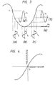
- a curve A in Fig. 3 shows the absorption spectrum of wavelength ⁇ A in Fig. 2.
- the light from the light source 10 has been modulated with the constant frequency f0 by the high frequency oscillator 24. Therefore, an intensity of the reflected light from the medium 15 which is detected by the optical detector 21, is necessarily modulated to some extent and the modulation may depend upon a deviation of light source wavelength from ⁇ A .
- Waveforms (b) and (e) in Fig. 3 are a modulating waveform and a modulated waveform, respectively, when the light source wavelength is coincident on the aimed wavelength.
- the output waveform (e) includes a frequency component having frequency twice the modulating frequency.
- a waveform (c) in Fig. 3 is a case where the light source wavelength is longer than the aimed wavelength.
- the waveform (c) has a frequency which is the same as the frequency f of the oscillator 24 and is in phase with the latter.
- the output waveform is modulated with the frequency f0, but the phase is inverted.
- an output such as shown in Fig. 4 is obtained by adding the output of the optical detector 21 to the phase detector 22 and phase-detecting it with the output of the high frequency oscillator 24.
- this output is obtained by applying this output to the wavelength regulator 25 to perform a servo control, it is possible to make the wavelength of the light source 10 always coincident on the aimed hole wavelength ⁇ A .
- an exact recording and reproducing of informations becomes possible.
- the wavelength regulation to be performed with respect to the hole according to the present invention may be done more effectively by using a recording and repoducing medium 15 such as shown in Fig. 5.
- the medium 15 has coaxial guide grooves although the grooves may be substituted by a spiral guide groove.
- a light spot on the medium moves along the medium with rotation thereof.
- the light source wavelength Due to such highly exact control of the light source wavelength, it is possible to scan the data in not the wavelength direction but the position direction. Therefore, the information can be recorded or reproduced continuously without loss of information even if a pit has a defect of such as dust or scratch.
- the scanning of data in the position direction makes the information reproducing speed higher than that obtainable by the scanning of the wavelength direction.
- a wavelength selective optical recording and reproducing device which is operable at high speed wih high reliability, due to the phase detection on the basis of the spectral hole and the wavelength control of the wavelength of the light source according to a deviation of the detected wavelength thereby.
Landscapes
- Physics & Mathematics (AREA)
- Life Sciences & Earth Sciences (AREA)
- Biophysics (AREA)
- Spectroscopy & Molecular Physics (AREA)
- Optical Recording Or Reproduction (AREA)
- Optical Head (AREA)
Applications Claiming Priority (2)
| Application Number | Priority Date | Filing Date | Title |
|---|---|---|---|
| JP154126/87 | 1987-06-19 | ||
| JP62154126A JPS63317936A (ja) | 1987-06-19 | 1987-06-19 | 光学的波長多重記録再生装置 |
Publications (3)
| Publication Number | Publication Date |
|---|---|
| EP0295682A2 true EP0295682A2 (fr) | 1988-12-21 |
| EP0295682A3 EP0295682A3 (fr) | 1991-01-09 |
| EP0295682B1 EP0295682B1 (fr) | 1993-11-03 |
Family
ID=15577479
Family Applications (1)
| Application Number | Title | Priority Date | Filing Date |
|---|---|---|---|
| EP88109653A Expired - Lifetime EP0295682B1 (fr) | 1987-06-19 | 1988-06-16 | Dispositif d'enregistrement et de reproduction optique, sélectif pour la longueur d'onde |
Country Status (6)
| Country | Link |
|---|---|
| US (1) | US4956812A (fr) |
| EP (1) | EP0295682B1 (fr) |
| JP (1) | JPS63317936A (fr) |
| KR (1) | KR910008497B1 (fr) |
| CA (1) | CA1301921C (fr) |
| DE (1) | DE3885353T2 (fr) |
Cited By (1)
| Publication number | Priority date | Publication date | Assignee | Title |
|---|---|---|---|---|
| WO1997040957A1 (fr) * | 1996-04-26 | 1997-11-06 | Servicio Industrial De Marcaje Y Codificacion, S.A. | Systeme et procede de marquage ou de perforation |
Families Citing this family (5)
| Publication number | Priority date | Publication date | Assignee | Title |
|---|---|---|---|---|
| FR2661769B1 (fr) * | 1990-05-02 | 1995-04-21 | Thomson Csf | Systeme d'enregistrement optique de donnees sur disque, et procedes de lecture et ecriture correspondants. |
| JP2744339B2 (ja) * | 1990-08-03 | 1998-04-28 | キヤノン株式会社 | 情報処理装置及び情報処理方法 |
| US5276637A (en) * | 1992-03-25 | 1994-01-04 | State Of Oregon Acting By And Through The State Board Of Higher Education On Behalf Of The University Of Oregon | Swept-carrier frequency selective optical memory and method |
| US6370169B1 (en) * | 1998-04-22 | 2002-04-09 | Nippon Telegraph & Telephone Corporation | Method and apparatus for controlling optical wavelength based on optical frequency pulling |
| KR100464615B1 (ko) * | 2002-06-27 | 2005-01-03 | 이제현 | 밀폐된 협소공간에서의 철판방식방법 |
Family Cites Families (8)
| Publication number | Priority date | Publication date | Assignee | Title |
|---|---|---|---|---|
| US4150392A (en) * | 1976-07-31 | 1979-04-17 | Nippon Gakki Seizo Kabushiki Kaisha | Semiconductor integrated flip-flop circuit device including merged bipolar and field effect transistors |
| US4079429A (en) * | 1977-01-18 | 1978-03-14 | Eastman Kodak Company | Optical detector for magnetic fields employing feedback circuitry |
| US4101976A (en) * | 1977-02-14 | 1978-07-18 | International Business Machines Corporation | Frequency selective optical data storage system |
| JPS5483848A (en) * | 1977-12-16 | 1979-07-04 | Mitsubishi Electric Corp | Automatic focusing device |
| JPH0627913B2 (ja) * | 1984-12-21 | 1994-04-13 | ソニー株式会社 | 光変調装置 |
| GB2187592B (en) * | 1985-12-26 | 1989-10-18 | Yokogawa Electric Corp | Semiconductor laser wavelength stabilizer |
| EP0265260B1 (fr) * | 1986-10-24 | 1993-09-01 | Hitachi, Ltd. | Procédé d'élimination d'enregistrement dans une mémoire utilisant un matériau du type photochemical hole burning |
| US4819206A (en) * | 1987-08-25 | 1989-04-04 | Mitsubishi Denki K.K. | Optical recording system |
-
1987
- 1987-06-19 JP JP62154126A patent/JPS63317936A/ja active Pending
-
1988
- 1988-04-21 KR KR1019880004530A patent/KR910008497B1/ko not_active Expired
- 1988-06-15 CA CA000569537A patent/CA1301921C/fr not_active Expired - Lifetime
- 1988-06-16 EP EP88109653A patent/EP0295682B1/fr not_active Expired - Lifetime
- 1988-06-16 DE DE88109653T patent/DE3885353T2/de not_active Expired - Fee Related
- 1988-06-20 US US07/209,213 patent/US4956812A/en not_active Expired - Lifetime
Cited By (2)
| Publication number | Priority date | Publication date | Assignee | Title |
|---|---|---|---|---|
| WO1997040957A1 (fr) * | 1996-04-26 | 1997-11-06 | Servicio Industrial De Marcaje Y Codificacion, S.A. | Systeme et procede de marquage ou de perforation |
| US6130402A (en) * | 1996-04-26 | 2000-10-10 | Servicio Industrial De Marcaje Y Codification, S.A. | System and process for marking or perforating |
Also Published As
| Publication number | Publication date |
|---|---|
| CA1301921C (fr) | 1992-05-26 |
| DE3885353D1 (de) | 1993-12-09 |
| EP0295682B1 (fr) | 1993-11-03 |
| US4956812A (en) | 1990-09-11 |
| KR890001034A (ko) | 1989-03-17 |
| EP0295682A3 (fr) | 1991-01-09 |
| KR910008497B1 (ko) | 1991-10-18 |
| JPS63317936A (ja) | 1988-12-26 |
| DE3885353T2 (de) | 1994-04-21 |
Similar Documents
| Publication | Publication Date | Title |
|---|---|---|
| US4611317A (en) | Optical disk apparatus | |
| US6411592B1 (en) | Optical information recording medium having convex and concave portions for recording information and an additional portion for condition data, and recording and reproducing apparatus for using the medium | |
| JP2783514B2 (ja) | 記録キャリヤに情報を記録する装置 | |
| US6418102B1 (en) | Method and apparatus for performing optimum laser power calibration on optical disks | |
| US4519056A (en) | Optical disk apparatus | |
| RU2060563C1 (ru) | Способ записи данных на оптический носитель информации со слоем записи и устройство для его осуществления | |
| US7406012B2 (en) | Semiconductor laser driving device, optical head device, optical information processing device, and optical recording medium | |
| JPH059852B2 (fr) | ||
| EP0295682A2 (fr) | Dispositif d'enregistrement et de reproduction optique, sélectif pour la longueur d'onde | |
| HU210013B (en) | Device for recording information on optical data carrier | |
| US5105076A (en) | Method and apparatus for detecting focusing errors utilizing chromatic aberration | |
| US5177727A (en) | Rotary recording medium having a guide track and recording and reproducing apparatus therefor | |
| JP2812441B2 (ja) | 光学的情報記録再生装置 | |
| US4841512A (en) | Optical disk apparatus with an erase checking function | |
| US5903533A (en) | Disc having at least one servo area pit formed out of phase for servo area identification | |
| KR19980076687A (ko) | 근접장 광학현상을 이용한 광 저장장치 및 이를 이용한 트랙킹 제어방법 | |
| EP0523334B1 (fr) | Milieu d'enregistrement d'information optique et dispositif pour la reproduction d'information de ce milieu | |
| US20040037195A1 (en) | Tilt correction device | |
| US5859830A (en) | Dynamic tracking control in an optical recording system by diffraction-based mark formation detection | |
| US4933923A (en) | Optical record carrier inscribed with read-out control data and apparatus for reading such record carrier in conformity with such control data | |
| US4868807A (en) | Wavelength selective optical data storage system | |
| JPH09147361A (ja) | 光学ディスク記録装置 | |
| KR930016960A (ko) | 광 디스크 장치 | |
| JP2008538152A (ja) | 識別可能なラベルを記述するシステム | |
| KR900006957B1 (ko) | 안내홈이 없는 광학 디스크의 정보신호 기록재생용 광학 헤드장치 |
Legal Events
| Date | Code | Title | Description |
|---|---|---|---|
| PUAI | Public reference made under article 153(3) epc to a published international application that has entered the european phase |
Free format text: ORIGINAL CODE: 0009012 |
|
| AK | Designated contracting states |
Kind code of ref document: A2 Designated state(s): DE FR GB |
|
| PUAL | Search report despatched |
Free format text: ORIGINAL CODE: 0009013 |
|
| AK | Designated contracting states |
Kind code of ref document: A3 Designated state(s): DE FR GB |
|
| 17P | Request for examination filed |
Effective date: 19901218 |
|
| 17Q | First examination report despatched |
Effective date: 19920318 |
|
| GRAA | (expected) grant |
Free format text: ORIGINAL CODE: 0009210 |
|
| AK | Designated contracting states |
Kind code of ref document: B1 Designated state(s): DE FR GB |
|
| REF | Corresponds to: |
Ref document number: 3885353 Country of ref document: DE Date of ref document: 19931209 |
|
| ET | Fr: translation filed | ||
| PLBE | No opposition filed within time limit |
Free format text: ORIGINAL CODE: 0009261 |
|
| STAA | Information on the status of an ep patent application or granted ep patent |
Free format text: STATUS: NO OPPOSITION FILED WITHIN TIME LIMIT |
|
| 26N | No opposition filed | ||
| REG | Reference to a national code |
Ref country code: GB Ref legal event code: 727 |
|
| REG | Reference to a national code |
Ref country code: GB Ref legal event code: 727A |
|
| REG | Reference to a national code |
Ref country code: GB Ref legal event code: 727B |
|
| REG | Reference to a national code |
Ref country code: GB Ref legal event code: SP |
|
| REG | Reference to a national code |
Ref country code: GB Ref legal event code: 746 Effective date: 19960611 |
|
| REG | Reference to a national code |
Ref country code: FR Ref legal event code: D6 |
|
| REG | Reference to a national code |
Ref country code: GB Ref legal event code: IF02 |
|
| PGFP | Annual fee paid to national office [announced via postgrant information from national office to epo] |
Ref country code: FR Payment date: 20020610 Year of fee payment: 15 |
|
| PGFP | Annual fee paid to national office [announced via postgrant information from national office to epo] |
Ref country code: GB Payment date: 20020612 Year of fee payment: 15 |
|
| PGFP | Annual fee paid to national office [announced via postgrant information from national office to epo] |
Ref country code: DE Payment date: 20020619 Year of fee payment: 15 |
|
| PG25 | Lapsed in a contracting state [announced via postgrant information from national office to epo] |
Ref country code: GB Free format text: LAPSE BECAUSE OF NON-PAYMENT OF DUE FEES Effective date: 20030616 |
|
| PG25 | Lapsed in a contracting state [announced via postgrant information from national office to epo] |
Ref country code: DE Free format text: LAPSE BECAUSE OF NON-PAYMENT OF DUE FEES Effective date: 20040101 |
|
| GBPC | Gb: european patent ceased through non-payment of renewal fee |
Effective date: 20030616 |
|
| PG25 | Lapsed in a contracting state [announced via postgrant information from national office to epo] |
Ref country code: FR Free format text: LAPSE BECAUSE OF NON-PAYMENT OF DUE FEES Effective date: 20040227 |
|
| REG | Reference to a national code |
Ref country code: FR Ref legal event code: ST |