EP0295705A2 - Projector-type head lamp for vehicles - Google Patents
Projector-type head lamp for vehicles Download PDFInfo
- Publication number
- EP0295705A2 EP0295705A2 EP88109696A EP88109696A EP0295705A2 EP 0295705 A2 EP0295705 A2 EP 0295705A2 EP 88109696 A EP88109696 A EP 88109696A EP 88109696 A EP88109696 A EP 88109696A EP 0295705 A2 EP0295705 A2 EP 0295705A2
- Authority
- EP
- European Patent Office
- Prior art keywords
- projector
- type head
- light
- shade
- head lamp
- Prior art date
- Legal status (The legal status is an assumption and is not a legal conclusion. Google has not performed a legal analysis and makes no representation as to the accuracy of the status listed.)
- Granted
Links
- 238000009826 distribution Methods 0.000 claims abstract description 21
- 229910001507 metal halide Inorganic materials 0.000 claims description 7
- 150000005309 metal halides Chemical class 0.000 claims description 7
- 239000006185 dispersion Substances 0.000 abstract description 7
- 230000003287 optical effect Effects 0.000 description 10
- 239000000306 component Substances 0.000 description 2
- 239000002131 composite material Substances 0.000 description 2
- QSHDDOUJBYECFT-UHFFFAOYSA-N mercury Chemical compound [Hg] QSHDDOUJBYECFT-UHFFFAOYSA-N 0.000 description 2
- 229910052753 mercury Inorganic materials 0.000 description 2
- 235000017060 Arachis glabrata Nutrition 0.000 description 1
- 241001553178 Arachis glabrata Species 0.000 description 1
- 235000010777 Arachis hypogaea Nutrition 0.000 description 1
- 235000018262 Arachis monticola Nutrition 0.000 description 1
- DGAQECJNVWCQMB-PUAWFVPOSA-M Ilexoside XXIX Chemical compound C[C@@H]1CC[C@@]2(CC[C@@]3(C(=CC[C@H]4[C@]3(CC[C@@H]5[C@@]4(CC[C@@H](C5(C)C)OS(=O)(=O)[O-])C)C)[C@@H]2[C@]1(C)O)C)C(=O)O[C@H]6[C@@H]([C@H]([C@@H]([C@H](O6)CO)O)O)O.[Na+] DGAQECJNVWCQMB-PUAWFVPOSA-M 0.000 description 1
- 238000004519 manufacturing process Methods 0.000 description 1
- 235000020232 peanut Nutrition 0.000 description 1
- 229910052708 sodium Inorganic materials 0.000 description 1
- 239000011734 sodium Substances 0.000 description 1
- 238000001228 spectrum Methods 0.000 description 1
- WFKWXMTUELFFGS-UHFFFAOYSA-N tungsten Chemical compound [W] WFKWXMTUELFFGS-UHFFFAOYSA-N 0.000 description 1
- 229910052721 tungsten Inorganic materials 0.000 description 1
- 239000010937 tungsten Substances 0.000 description 1
Images


Classifications
-
- F—MECHANICAL ENGINEERING; LIGHTING; HEATING; WEAPONS; BLASTING
- F21—LIGHTING
- F21S—NON-PORTABLE LIGHTING DEVICES; SYSTEMS THEREOF; VEHICLE LIGHTING DEVICES SPECIALLY ADAPTED FOR VEHICLE EXTERIORS
- F21S41/00—Illuminating devices specially adapted for vehicle exteriors, e.g. headlamps
- F21S41/40—Illuminating devices specially adapted for vehicle exteriors, e.g. headlamps characterised by screens, non-reflecting members, light-shielding members or fixed shades
- F21S41/43—Illuminating devices specially adapted for vehicle exteriors, e.g. headlamps characterised by screens, non-reflecting members, light-shielding members or fixed shades characterised by the shape thereof
-
- F—MECHANICAL ENGINEERING; LIGHTING; HEATING; WEAPONS; BLASTING
- F21—LIGHTING
- F21S—NON-PORTABLE LIGHTING DEVICES; SYSTEMS THEREOF; VEHICLE LIGHTING DEVICES SPECIALLY ADAPTED FOR VEHICLE EXTERIORS
- F21S41/00—Illuminating devices specially adapted for vehicle exteriors, e.g. headlamps
- F21S41/10—Illuminating devices specially adapted for vehicle exteriors, e.g. headlamps characterised by the light source
- F21S41/14—Illuminating devices specially adapted for vehicle exteriors, e.g. headlamps characterised by the light source characterised by the type of light source
- F21S41/17—Discharge light sources
- F21S41/172—High-intensity discharge light sources
Definitions
- the present invention relates to a projector-type head lamp for use on vehicles, and more particularly to a projector-type head lamp with which no colored light zone will appear near the light-dark limit of a luminous intensity distribution pattern formed by a light beam projected after shaped into an appropriate form by a shade disposed between a light source and a convex lens.
- the head lamps of a car are required to brightly illuminate the lane surface in front of the car in a luminous intensity distribution pattern which will not dazzle the driver of a car running on the opposite lane.
- the so-called projector-type head lamps have been proposed as a head lamp of which the optical system is simple and which can be designed compact as a whole.
- the optical system of one example of such head lamps of projector type is schematically shown in Fig. 1.
- the projector-type head lamp comprises a reflector 10 of which the inside reflective surface may be shaped in any of many dif ferent geometrical forms, for example, a spheroidal form.
- an incandescent lamp 12 having a filament 14 positioned at the inner focus F1 of the reflector 10, and a shade 16 is disposed near the outer focus F2 to shape into an appropriate form the light reflected by the reflective surface.
- a convex lens 18 having a focal plane i-j with which the outer focus F2 of the reflector 10 coincides. The light emitted from the light source is reflected by the reflector 10 and incident upon the outer focus F2 of the reflector 10 where it is shaped by the shade 16.
- the shade 16 has the top thereof cut as shown in Fig. 2 (cut line indicated with the reference number 20). The light incident upon the shade 16 is shaped as partially blocked, and the light thus shaped is projected frontward through the convex lens 18.
- the luminous intensity distribution pattern on a screen disposed in a position about 10 meters from the light source is shown in the form of an isolux curve in Fig. 4.
- a conventional protector-type head lamp With such a conventional protector-type head lamp, the light incident upon the convex lens 18 outgoes generally horizontally as considered from the standpoint of geometrical optics, but since the light source is a coiled tungsten filament, the light is not a light of single wavelength in practice. Hence, a phenomenon takes place that light beams different in wavelength from one another and incident upon the convex lens 18 are refracted in different directions depending upon their respective wavelengths. This is called a "dispersion". This light dispersion will be described with reference to Fig. 3.
- the filament as light source is an axial or longitudinal coil which will cause an uneven brightness distribution in which zones of maximum and minimum brightness appear alternately. Also the luminous intensity distribution pattern is influenced by such uneven brightness distribution.
- the luminous intensity distribution pattern resulted from the converging of the light emitted from the filament and reflected by the reflective surface takes a peanut-like form, that is, the central upper and lower portions of the pattern are concave downward and upward, respectively.
- the luminous intensity distribution pattern projected through the convex lens after shaped by the shade has also the central lower portion thereof still remained concave. So, an improved optical system is needed to provide an ideal luminous intensity distribution pattern.
- the present invention seeks to provide a projector-type head lamp adopting a simple optical system capable of providing an ideal luminous intensity distribution pattern.
- a projector-type head lamp is provided with which an iridescent zone developed near the light-dark limit of a luminous intensity pattern projected frontward can be eliminated.
- a projector-type head lamp is provided with which the bright zone of a projected luminous intensity distribution pattern is not influenced by any brightness distribution of the light source.
- Fig. 5 schematically shows the optical system of the projector-type head lamp according to the present invention.
- the protector-type head lamp according to the present invention differs in the following respects from the conventional pro jector-type head lamp. Namely,
- the light source adopted is not a linear filament of which the brightness distribution is discrete, but a discharge lamp 30 of which the brightness distribution is spatially continuous.
- the convex lens 32 is a single lens.
- the present invention requires no composite lens.
- the discharge lamp 30 is well known per se, has a higher luminous efficacy and a longer life than the incandescent lamp, however,the discharge lamp is not used in the ordinary lamp units for vehicles.
- the discharge lamp 30 adopted is a metal halide lamp of 35 W which is energized by battery.
- the metal halide lamp is disposed with the intermediate point between the anode and cathode of the metal halide lamp being nearly coincident with the inner focus F1 of a reflector 10 of which the inside reflective surface is a spheroidal one, and a shade 16 is disposed near the outer focus F2 of the reflector 10.
- a single lens 32 used in the head lamp has a generally flat incident surface at the side facing the reflector 10 and a convex outgoing surface at the side away from the reflector 10.
- the lens 32 has a focal plane located as nearly coincident with the outer focus F2 of the reflector 10.
- the light emitting tube of the metal halide lamp is charged with mercury and a metal halide which are evaporated when heated with a preheater (not shown). There is a gap of about 5 mm between the anode and cathode.
- a high voltage pulse from a DC source that is, a battery
- a DC discharge is made between the anode and cathode and a generally uniform light source is provided of which the brightness distribution takes a spatially continuous football-shaped pattern formed around the mid point between the anode and cathode.
- This light source 30 is a monochromic one of 4,000 K in color temperature, and has no continuous spectrum as the incandescent lamp. So, use of a single lens 32 as convex lens will not cause any colored light zone near the light-dark limit of the luminous intensity distribution pattern.
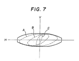
- the pattern composed of light beams reflected on the entire reflective surface takes the form of a football as shown in Fig. 7.
- This pattern has the features that the central upper and lower portions of the pattern are not concave as in case a filament is disposed in a reflector of which the inside reflective surface is a a spheroidal one. Namely, the pattern does not take the form of a peanut, but a football shape of which the top and bottom are nearly flat.
- the light beam shaped by the shade 16 and projected through the convex lens 32 produces an ideal luminous intensity distribution pattern with no dark concave portion at the central lower portion thereof.
- a metal halide lamp is used as discharge lamp in this embodiment, but a sodium lamp or high pressure mercury lamp may be used instead.
- the reflector 10 used has a spheroidal inside reflective surface, but the inside reflective surface is not limited to this geometrical shape.
- the reflector 10 may be a one which has an inside reflective surface of any one of various geometrical shapes which can be adopted in the conventional projector-type head lamps.
Landscapes
- Engineering & Computer Science (AREA)
- General Engineering & Computer Science (AREA)
- Non-Portable Lighting Devices Or Systems Thereof (AREA)
Abstract
Description
- The present invention relates to a projector-type head lamp for use on vehicles, and more particularly to a projector-type head lamp with which no colored light zone will appear near the light-dark limit of a luminous intensity distribution pattern formed by a light beam projected after shaped into an appropriate form by a shade disposed between a light source and a convex lens.
- Generally, the head lamps of a car are required to brightly illuminate the lane surface in front of the car in a luminous intensity distribution pattern which will not dazzle the driver of a car running on the opposite lane. To meet these requirements, the so-called projector-type head lamps have been proposed as a head lamp of which the optical system is simple and which can be designed compact as a whole. The optical system of one example of such head lamps of projector type is schematically shown in Fig. 1. Generally, the projector-type head lamp comprises a
reflector 10 of which the inside reflective surface may be shaped in any of many dif ferent geometrical forms, for example, a spheroidal form. There is disposed anincandescent lamp 12 having afilament 14 positioned at the inner focus F1 of thereflector 10, and ashade 16 is disposed near the outer focus F2 to shape into an appropriate form the light reflected by the reflective surface. Also there is disposed aconvex lens 18 having a focal plane i-j with which the outer focus F2 of thereflector 10 coincides. The light emitted from the light source is reflected by thereflector 10 and incident upon the outer focus F2 of thereflector 10 where it is shaped by theshade 16. Theshade 16 has the top thereof cut as shown in Fig. 2 (cut line indicated with the reference number 20). The light incident upon theshade 16 is shaped as partially blocked, and the light thus shaped is projected frontward through theconvex lens 18. The luminous intensity distribution pattern on a screen disposed in a position about 10 meters from the light source is shown in the form of an isolux curve in Fig. 4. With such a conventional protector-type head lamp, the light incident upon theconvex lens 18 outgoes generally horizontally as considered from the standpoint of geometrical optics, but since the light source is a coiled tungsten filament, the light is not a light of single wavelength in practice. Hence, a phenomenon takes place that light beams different in wavelength from one another and incident upon theconvex lens 18 are refracted in different directions depending upon their respective wavelengths. This is called a "dispersion". This light dispersion will be described with reference to Fig. 3. Among the light beams incident upon the upper portion of theconvex lens 18, those of large wave-lengths (lights going toward red) are refracted upward with respect to the horizontal direction, while the light beams of small wavelengths (lights going toward purple) are refracted downward with respect to the horizontal direction. Of the light beams incident upon the lower portion of theconvex lens 18, those of large wavelengths are refracted downward with respect to the horizontal direction, while the light beams of small wavelengths are refracted upward with respect to the horizontal direction. With such a projector-type head lamp, as an influence due to the above-mentioned dispersion appears within adark area 24 along a light-dark limit 22 defined by thecut line 20 of theshade 16, namely, since a colored light appears above the light-dark limit 22, an iridescent zone develops within thedark area 24. THis phenomenon is rather much caused by the light components refracted upwardly with respect to the horizontal direction, than by the light components refracted downwardly with respect to the horizontal direction. To reduce such dispersion, a so-called composite lens structure may be adopted, but this is not economic because its manufacturing costs are high. Further, in the conventional projector-type head lamps, the filament as light source is an axial or longitudinal coil which will cause an uneven brightness distribution in which zones of maximum and minimum brightness appear alternately. Also the luminous intensity distribution pattern is influenced by such uneven brightness distribution. - In case a reflector of which the inside reflective surface is a spheroidal one is employed in a projector-type head lamp, the luminous intensity distribution pattern resulted from the converging of the light emitted from the filament and reflected by the reflective surface takes a peanut-like form, that is, the central upper and lower portions of the pattern are concave downward and upward, respectively. As shown in Fig. 4, the luminous intensity distribution pattern projected through the convex lens after shaped by the shade has also the central lower portion thereof still remained concave. So, an improved optical system is needed to provide an ideal luminous intensity distribution pattern.
- The present invention seeks to provide a projector-type head lamp adopting a simple optical system capable of providing an ideal luminous intensity distribution pattern.
- According to another object of the present invention, a projector-type head lamp is provided with which an iridescent zone developed near the light-dark limit of a luminous intensity pattern projected frontward can be eliminated.
- According to a still another object of the present invention, a projector-type head lamp is provided with which the bright zone of a projected luminous intensity distribution pattern is not influenced by any brightness distribution of the light source.
- These and other objects and advantages of the present invention will be better understood from the ensuing description made, by way of example, of the embodiment according to the present invention with reference to the drawings.
-
- Fig. 1 is a schematic front view of the optical system of a conventional protector-type head lamp;
- Fig. 2 is a side elevation of the optical system shown in Fig. 1;
- Fig. 3 is a drawing intended for explanation of the dispersion through the convex lens in the optical system;
- Fig. 4 is an isolux curve intended for explanation of the influence of the dispersion through the convex lens on the luminous intensity distribution pattern projected frontward;
- Figs. 5 thru 7 show one embodiment of the projector-type head lamp according to the present invention, in which
- Fig. 5 is a schematic front view of the optical system;
- Fig. 6 is a schematic side elevation of the optical system shown in Fig. 5; and
- Fig. 7 is a schematic luminous intensity distribution pattern intended for explanation of the shape of reflected light pattern on a screen disposed in the place of the shade.
- Fig. 5 schematically shows the optical system of the projector-type head lamp according to the present invention. The protector-type head lamp according to the present invention differs in the following respects from the conventional pro jector-type head lamp. Namely, The light source adopted is not a linear filament of which the brightness distribution is discrete, but a
discharge lamp 30 of which the brightness distribution is spatially continuous. Theconvex lens 32 is a single lens. The present invention requires no composite lens. Thedischarge lamp 30 is well known per se, has a higher luminous efficacy and a longer life than the incandescent lamp, however,the discharge lamp is not used in the ordinary lamp units for vehicles. In the embodiment of the protector-type head lamp according to the present invention, thedischarge lamp 30 adopted is a metal halide lamp of 35 W which is energized by battery. The metal halide lamp is disposed with the intermediate point between the anode and cathode of the metal halide lamp being nearly coincident with the inner focus F1 of areflector 10 of which the inside reflective surface is a spheroidal one, and ashade 16 is disposed near the outer focus F2 of thereflector 10. Asingle lens 32 used in the head lamp has a generally flat incident surface at the side facing thereflector 10 and a convex outgoing surface at the side away from thereflector 10. Thelens 32 has a focal plane located as nearly coincident with the outer focus F2 of thereflector 10. The light emitting tube of the metal halide lamp is charged with mercury and a metal halide which are evaporated when heated with a preheater (not shown). There is a gap of about 5 mm between the anode and cathode. When a high voltage pulse from a DC source, that is, a battery, is applied between the anode and cathode, a DC discharge is made between the anode and cathode and a generally uniform light source is provided of which the brightness distribution takes a spatially continuous football-shaped pattern formed around the mid point between the anode and cathode. Thislight source 30 is a monochromic one of 4,000 K in color temperature, and has no continuous spectrum as the incandescent lamp. So, use of asingle lens 32 as convex lens will not cause any colored light zone near the light-dark limit of the luminous intensity distribution pattern. - The light beams reflected at the points a, b and c on the reflective surface of the
reflector 10, as shown in Fig. 6, produce, on a screen disposed near theshade 16, patterns indicated with dash lines A, B and C, respectively, as shown in Fig. 7. It will be thus apparent that the pattern composed of light beams reflected on the entire reflective surface takes the form of a football as shown in Fig. 7. This pattern has the features that the central upper and lower portions of the pattern are not concave as in case a filament is disposed in a reflector of which the inside reflective surface is a a spheroidal one. Namely, the pattern does not take the form of a peanut, but a football shape of which the top and bottom are nearly flat. Thus, the light beam shaped by theshade 16 and projected through theconvex lens 32 produces an ideal luminous intensity distribution pattern with no dark concave portion at the central lower portion thereof. - A metal halide lamp is used as discharge lamp in this embodiment, but a sodium lamp or high pressure mercury lamp may be used instead.
- In the embodiment having been described in the foregoing, the
reflector 10 used has a spheroidal inside reflective surface, but the inside reflective surface is not limited to this geometrical shape. Of course, thereflector 10 may be a one which has an inside reflective surface of any one of various geometrical shapes which can be adopted in the conventional projector-type head lamps.
Claims (4)
a reflector having an inside reflective surface of a predetermined geometrical shape and provided with a light source at one of the foci thereof;
a shade disposed near the other focus of said reflector and which is intended to shape the light beam reflected at said inside reflective surface; and
a lens means of converging the light beam shaped by said shade and having a focal plane near the other focus of said reflector;
said light source being a discharge lamp having a single color temperature.
Applications Claiming Priority (2)
| Application Number | Priority Date | Filing Date | Title |
|---|---|---|---|
| JP62149236A JP2691712B2 (en) | 1987-06-17 | 1987-06-17 | Projector type vehicle headlight |
| JP149236/87 | 1987-06-17 |
Publications (3)
| Publication Number | Publication Date |
|---|---|
| EP0295705A2 true EP0295705A2 (en) | 1988-12-21 |
| EP0295705A3 EP0295705A3 (en) | 1989-11-15 |
| EP0295705B1 EP0295705B1 (en) | 1993-04-07 |
Family
ID=15470855
Family Applications (1)
| Application Number | Title | Priority Date | Filing Date |
|---|---|---|---|
| EP88109696A Revoked EP0295705B1 (en) | 1987-06-17 | 1988-06-16 | Projector-type head lamp for vehicles |
Country Status (4)
| Country | Link |
|---|---|
| US (1) | US4879636A (en) |
| EP (1) | EP0295705B1 (en) |
| JP (1) | JP2691712B2 (en) |
| DE (1) | DE3880020T2 (en) |
Cited By (3)
| Publication number | Priority date | Publication date | Assignee | Title |
|---|---|---|---|---|
| EP0390208A3 (en) * | 1989-03-31 | 1991-10-23 | Ichikoh Industries Limited | Projector-type head lamp for motor vehicles |
| FR2666400A1 (en) * | 1990-08-31 | 1992-03-06 | Koito Mfg Co Ltd | PROJECTION TYPE VEHICLE HEADLIGHT. |
| DE4138082A1 (en) * | 1990-11-20 | 1992-06-11 | Koito Mfg Co Ltd | MOTOR VEHICLE HEADLIGHTS |
Families Citing this family (11)
| Publication number | Priority date | Publication date | Assignee | Title |
|---|---|---|---|---|
| JP2517368B2 (en) * | 1988-09-27 | 1996-07-24 | 株式会社小糸製作所 | Vehicle headlight and vehicle headlight device |
| IT214875Z2 (en) * | 1988-11-22 | 1990-07-04 | Carello Spa | MOTOR VEHICLE PROJECTOR |
| US5307247A (en) * | 1992-09-22 | 1994-04-26 | Autopal, Statni Podnik | Headlamp for motor vehicles |
| US5618102A (en) * | 1995-06-07 | 1997-04-08 | Adac Plastics, Inc. | Plasma discharge lamp |
| CZ299345B6 (en) | 2003-10-06 | 2008-06-25 | Visteon Global Technologies, Inc. | Variable adaptive headlight system for motor vehicles |
| JP2006049189A (en) | 2004-08-06 | 2006-02-16 | Koito Mfg Co Ltd | Vehicle headlamp |
| JP2006049190A (en) | 2004-08-06 | 2006-02-16 | Koito Mfg Co Ltd | Vehicle headlamp |
| US7625109B2 (en) | 2005-06-30 | 2009-12-01 | Koito Manufacturing Co., Ltd. | Vehicle lamp |
| US7357545B2 (en) * | 2005-08-10 | 2008-04-15 | Visteon Global Technologies, Inc. | Multi-focal lens for bi-functional headlamp |
| KR101358423B1 (en) * | 2012-08-31 | 2014-02-04 | 주식회사 에스엘 서봉 | System and method for controlling automotive head lamp |
| CZ2015224A3 (en) | 2015-03-30 | 2017-01-18 | Varroc Lighting Systems, s.r.o. | A method and equipment for reducing the edges of a light image of a headlamp and a headlamp |
Family Cites Families (18)
| Publication number | Priority date | Publication date | Assignee | Title |
|---|---|---|---|---|
| DE2461918A1 (en) * | 1974-01-11 | 1975-07-17 | Faulhaber Fritz | Motor car spot lamp - with narrow angle beam of high intensity and gas discharge light source |
| AU505317B2 (en) * | 1976-08-23 | 1979-11-15 | Thorn Electrical Industries Limited | Suppression of colour fringing in lamps |
| DE3241713A1 (en) * | 1982-11-11 | 1984-05-17 | Westfälische Metall Industrie KG Hueck & Co, 4780 Lippstadt | DIMMED HEADLIGHT FOR MOTOR VEHICLES |
| US4513357A (en) * | 1983-01-19 | 1985-04-23 | Tokyo Shibaura Denki Kabushiki Kaisha | Headlamp unit with timed switching between two lights |
| FR2550847B1 (en) * | 1983-08-18 | 1988-07-01 | Cibie Projecteurs | ELLIPTICAL REFLECTOR WITH CUT BEAM FOR MOTOR VEHICLE |
| JPS6084702A (en) * | 1983-08-31 | 1985-05-14 | 東芝ライテック株式会社 | Headlamp for vehicle |
| FR2566878B1 (en) * | 1984-06-27 | 1986-07-18 | Cibie Projecteurs | IMPROVEMENTS ON AUTOMOTIVE PROJECTORS EMITTING A CUTTING BEAM, ESPECIALLY A CROSSING BEAM |
| JPS6135304U (en) * | 1984-08-07 | 1986-03-04 | 株式会社東芝 | vehicle headlights |
| DE3516812A1 (en) * | 1985-05-10 | 1986-11-13 | Hella KG Hueck & Co, 4780 Lippstadt | Dimmed vehicle headlights |
| DE3519271C1 (en) * | 1985-05-30 | 1986-08-28 | Westfälische Metall Industrie KG Hueck & Co, 4780 Lippstadt | Dimmed vehicle headlights based on the projection principle |
| DE3527391A1 (en) * | 1985-07-31 | 1987-02-05 | Bosch Gmbh Robert | FOG LIGHTS FOR MOTOR VEHICLES |
| DE3529546C1 (en) * | 1985-08-17 | 1987-02-05 | Hella Kg Hueck & Co | Dimmed vehicle headlights with an ellipsoidal reflector |
| DE3531224A1 (en) * | 1985-08-31 | 1987-03-05 | Bosch Gmbh Robert | HEADLIGHTS FOR LOW BEAM OR FOG LIGHTS OF MOTOR VEHICLES |
| JPH0773001B2 (en) * | 1985-10-18 | 1995-08-02 | 東芝ライテック株式会社 | Projection light source device |
| JPS6277806U (en) * | 1985-11-05 | 1987-05-19 | ||
| DE3603743A1 (en) * | 1986-02-06 | 1987-08-13 | Patent Treuhand Ges Fuer Elektrische Gluehlampen Mbh | HIGH PRESSURE DISCHARGE LAMP FOR USE IN MOTOR VEHICLE HEADLIGHTS |
| US4754373A (en) * | 1986-10-14 | 1988-06-28 | General Electric Company | Automotive headlamp |
| DE3641852A1 (en) * | 1986-12-08 | 1988-06-16 | Patent Treuhand Ges Fuer Elektrische Gluehlampen Mbh | VEHICLE HEADLIGHT UNIT |
-
1987
- 1987-06-17 JP JP62149236A patent/JP2691712B2/en not_active Expired - Lifetime
-
1988
- 1988-06-16 DE DE8888109696T patent/DE3880020T2/en not_active Revoked
- 1988-06-16 EP EP88109696A patent/EP0295705B1/en not_active Revoked
- 1988-06-17 US US07/207,815 patent/US4879636A/en not_active Expired - Lifetime
Cited By (4)
| Publication number | Priority date | Publication date | Assignee | Title |
|---|---|---|---|---|
| EP0390208A3 (en) * | 1989-03-31 | 1991-10-23 | Ichikoh Industries Limited | Projector-type head lamp for motor vehicles |
| FR2666400A1 (en) * | 1990-08-31 | 1992-03-06 | Koito Mfg Co Ltd | PROJECTION TYPE VEHICLE HEADLIGHT. |
| DE4128906A1 (en) * | 1990-08-31 | 1992-03-12 | Koito Mfg Co Ltd | VEHICLE PROJECTION HEADLIGHTS |
| DE4138082A1 (en) * | 1990-11-20 | 1992-06-11 | Koito Mfg Co Ltd | MOTOR VEHICLE HEADLIGHTS |
Also Published As
| Publication number | Publication date |
|---|---|
| EP0295705B1 (en) | 1993-04-07 |
| US4879636A (en) | 1989-11-07 |
| JPS63314701A (en) | 1988-12-22 |
| DE3880020D1 (en) | 1993-05-13 |
| EP0295705A3 (en) | 1989-11-15 |
| DE3880020T2 (en) | 1993-07-15 |
| JP2691712B2 (en) | 1997-12-17 |
Similar Documents
| Publication | Publication Date | Title |
|---|---|---|
| US6402355B1 (en) | Vehicular headlamp having improved low-beam illumination | |
| EP0950847B1 (en) | Lamp, in particular for vehicles or traffic signal applications | |
| US6416210B1 (en) | Headlamp for a vehicle | |
| US4879636A (en) | Projector-type head lamp for vehicles | |
| US7029155B2 (en) | Motor vehicle headlight with at least two functions | |
| EP1085254A2 (en) | Multi-lens projector lamp | |
| US7178957B2 (en) | Multiple-filament motor vehicle headlight lamp | |
| CA1064089A (en) | Rectangular headlamp filament shield | |
| CN208269025U (en) | Reflex reflector | |
| US4760501A (en) | Headlamp system | |
| JP2005044807A (en) | Light emitting diode module for vehicle headlamp and vehicle headlamp | |
| US5709451A (en) | High intensity descharge bulb parabolic reflector vehicle headlamp | |
| WO1987006325A1 (en) | Head lamp, in particular headlight for cars, provided with several filaments adapted to emit beams of white and/or coloured light to be used as sealed beam light and foglight | |
| GB2337322A (en) | Combined fog lamp and high beam lamp for vehicle headlamp | |
| KR20200013294A (en) | lamp for vehicle | |
| KR20060057612A (en) | Lamp for a motor vehicle headlight | |
| US3206595A (en) | Vehicle headlamp and incandescent lamp for the same | |
| US5826964A (en) | Headlamp with complex reflector | |
| CN114321828A (en) | Vehicle lamps | |
| JP3261847B2 (en) | Projector-type headlights that prevent color development | |
| KR0145819B1 (en) | Headlamp | |
| JP3145928B2 (en) | Vehicle headlights | |
| CN119713168A (en) | Front combination lamps of a vehicle and a vehicle | |
| JPS6026401Y2 (en) | vehicle head lamp | |
| KR800000640Y1 (en) | Fluorescent lamp |
Legal Events
| Date | Code | Title | Description |
|---|---|---|---|
| PUAI | Public reference made under article 153(3) epc to a published international application that has entered the european phase |
Free format text: ORIGINAL CODE: 0009012 |
|
| AK | Designated contracting states |
Kind code of ref document: A2 Designated state(s): DE FR GB |
|
| PUAL | Search report despatched |
Free format text: ORIGINAL CODE: 0009013 |
|
| AK | Designated contracting states |
Kind code of ref document: A3 Designated state(s): DE FR GB |
|
| 17P | Request for examination filed |
Effective date: 19891213 |
|
| 17Q | First examination report despatched |
Effective date: 19911119 |
|
| GRAA | (expected) grant |
Free format text: ORIGINAL CODE: 0009210 |
|
| AK | Designated contracting states |
Kind code of ref document: B1 Designated state(s): DE FR GB |
|
| ET | Fr: translation filed | ||
| REF | Corresponds to: |
Ref document number: 3880020 Country of ref document: DE Date of ref document: 19930513 |
|
| PLBI | Opposition filed |
Free format text: ORIGINAL CODE: 0009260 |
|
| PLBI | Opposition filed |
Free format text: ORIGINAL CODE: 0009260 |
|
| 26 | Opposition filed |
Opponent name: ROBERT BOSCH GMBH Effective date: 19931216 |
|
| 26 | Opposition filed |
Opponent name: HELLA KG HUECK & CO. Effective date: 19931224 Opponent name: ROBERT BOSCH GMBH Effective date: 19931216 |
|
| PLBI | Opposition filed |
Free format text: ORIGINAL CODE: 0009260 |
|
| 26 | Opposition filed |
Opponent name: BAYERISCHE MOTOREN WERKE AKTIENGESELLSCHAFT Effective date: 19931223 Opponent name: HELLA KG HUECK & CO. Effective date: 19931224 Opponent name: ROBERT BOSCH GMBH Effective date: 19931216 |
|
| PGFP | Annual fee paid to national office [announced via postgrant information from national office to epo] |
Ref country code: GB Payment date: 19970522 Year of fee payment: 10 |
|
| PGFP | Annual fee paid to national office [announced via postgrant information from national office to epo] |
Ref country code: FR Payment date: 19970617 Year of fee payment: 10 |
|
| PGFP | Annual fee paid to national office [announced via postgrant information from national office to epo] |
Ref country code: DE Payment date: 19970730 Year of fee payment: 10 |
|
| APAC | Appeal dossier modified |
Free format text: ORIGINAL CODE: EPIDOS NOAPO |
|
| RDAH | Patent revoked |
Free format text: ORIGINAL CODE: EPIDOS REVO |
|
| RDAG | Patent revoked |
Free format text: ORIGINAL CODE: 0009271 |
|
| STAA | Information on the status of an ep patent application or granted ep patent |
Free format text: STATUS: PATENT REVOKED |
|
| 27W | Patent revoked |
Effective date: 19971017 |
|
| GBPR | Gb: patent revoked under art. 102 of the ep convention designating the uk as contracting state |
Free format text: 971017 |
|
| APAH | Appeal reference modified |
Free format text: ORIGINAL CODE: EPIDOSCREFNO |