EP0295753B1 - Bindestreifen aus elastischem deformierbarem Material - Google Patents
Bindestreifen aus elastischem deformierbarem Material Download PDFInfo
- Publication number
- EP0295753B1 EP0295753B1 EP88201231A EP88201231A EP0295753B1 EP 0295753 B1 EP0295753 B1 EP 0295753B1 EP 88201231 A EP88201231 A EP 88201231A EP 88201231 A EP88201231 A EP 88201231A EP 0295753 B1 EP0295753 B1 EP 0295753B1
- Authority
- EP
- European Patent Office
- Prior art keywords
- strip
- projections
- slotted
- slotted opening
- binding
- Prior art date
- Legal status (The legal status is an assumption and is not a legal conclusion. Google has not performed a legal analysis and makes no representation as to the accuracy of the status listed.)
- Expired - Lifetime
Links
- 239000000463 material Substances 0.000 title claims abstract description 18
- 230000001154 acute effect Effects 0.000 claims description 3
- 238000010276 construction Methods 0.000 description 3
- 229910000831 Steel Inorganic materials 0.000 description 2
- 239000010959 steel Substances 0.000 description 2
- 238000004519 manufacturing process Methods 0.000 description 1
- 238000012856 packing Methods 0.000 description 1
- 238000004064 recycling Methods 0.000 description 1
Images

Classifications
-
- A—HUMAN NECESSITIES
- A01—AGRICULTURE; FORESTRY; ANIMAL HUSBANDRY; HUNTING; TRAPPING; FISHING
- A01G—HORTICULTURE; CULTIVATION OF VEGETABLES, FLOWERS, RICE, FRUIT, VINES, HOPS OR SEAWEED; FORESTRY; WATERING
- A01G17/00—Cultivation of hops, vines, fruit trees, or like trees
- A01G17/04—Supports for hops, vines, or trees
- A01G17/06—Trellis-work
- A01G17/08—Tools e.g. clips for attaching hops, vines, or boughs to trellis-work; Tying devices
-
- B—PERFORMING OPERATIONS; TRANSPORTING
- B65—CONVEYING; PACKING; STORING; HANDLING THIN OR FILAMENTARY MATERIAL
- B65D—CONTAINERS FOR STORAGE OR TRANSPORT OF ARTICLES OR MATERIALS, e.g. BAGS, BARRELS, BOTTLES, BOXES, CANS, CARTONS, CRATES, DRUMS, JARS, TANKS, HOPPERS, FORWARDING CONTAINERS; ACCESSORIES, CLOSURES, OR FITTINGS THEREFOR; PACKAGING ELEMENTS; PACKAGES
- B65D63/00—Flexible elongated elements, e.g. straps, for bundling or supporting articles
- B65D63/10—Non-metallic straps, tapes, or bands; Filamentary elements, e.g. strings, threads or wires; Joints between ends thereof
Definitions
- the invention relates to a set of binding strips consisting of an elastic, deformable material, a strip being provided with at least two corresponding slotted openings and a number of corresponding projections located spaced from each other in the longitudinal direction of the strip and extending transversely to the longitudinal direction of the strip, on both edges of the strip all this such that when a part of the strip comprising projections is twisted over an anlge of ⁇ 90 ° relatively to a part of the strip having a slotted opening, at least said part of the strip having projections can be moved through said slotted opening and will have projections co-operating with the boundary wall of said slotted opening when afterwards the strip is twisted back again into its original shape.
- Such a binding strip is known from the DE-A 753 420.
- the one strip half is provided with a number of slotted openings, whilst the other strip half has the projections.
- the NL-A 120 277 discloses an embodiment whereby the slotted openings are provided regularly spaced from each other along the entire length of the strip and are bounded by parts forming projections.
- a disadvantage of this construction is that a comparatively great deal of material is lost in production, whilst the distance between the successive effective projections for fixing the strip is comparatively large.
- the purpose of the invention is to obtain a binding strip of the above kind, with which the disadvantages of the known binding strips can be met.
- the aim is to obtain a binding strip suitable for tying up refuse bags, which strip is completely made of plastic material.
- a disadvantage of the binding strips used for this purpose so far is that they contain steel wire. When such binding strips are used it is namely necessary to remove the binding strips when a parcel of refuse bags is rejected, in order to prepare the material of the rejected refuse bags for recycling so as to prevent that the steel wires damage the processing machines.
- a set of binding strips whereby between each pair of successive slotted openings there are provided on both edges of the strip at least one group of projections, such that the mutual distances between said projections in a group of projections and the distance between the part of the strip having a slotted opening and the projections located closest thereto is equal to at least substantially the width of a projection, whilst the distance between the outer projections located closest together of two groups of projections located between two parts of the strip having slotted openings or the distance between the outer projection of one group of projections and the part of the strip having a slotted opening is at least substantially equal to the length of the part of the strip having the slotted opening; the arrangement being such that the projections and the part of the strip having a slotted opening fit between the projections and the part of the strip having a slotted opening of an adjacent binding strip.
- a binding strip may be cut at random from a strip of material comprising a number of binding strips and yet be fixed in an effective manner, whereby the distance between at least a number of the successive projections can be kept comparatively small.
- binding strips have been designed in such a way that the projections and the parts having the slotted holes of binding strip fit between the corresponding parts of a similar binding strips said binding strips can be formed in sheet like material with a minimum of lost material; in fact only the material coming out of th slotted openings will be lost.
- US-A 4 477 950 discloses a binding strip having projections, at one end a slotted hole and the other end a tapered extension.
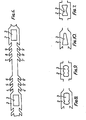
- the binding strip illustrated in fig 1 preferably made of plastic material, comprises elongated connecting parts 1 which form a unit with rectangular connecting pieces 2 connected together by said connecting parts 1, in which connecting pieces 2 there are formed elongated slotted openings 3.
- Each connecting part 1 is furthermore provided with six projections 4 - 9 on one side, and with six projections 4' - 9' located diametrically opposite the projections 4 - 9 on the other side.
- each set of three projections located most closely near a connecting piece and the distance between a connecting piece and the nearest projection 4 or 9 is equal to the width of a projection, as will be apparent from fig 1, whilst the distance between two groups of three equally spaced projections 4 - 6 and 7 - 9 respectively, located on the same side of a connecting part, is equal to the length of a connecting piece 2.
- a binding strip When a binding strip is to be used it may be cut off to a length equal to the distance a between the two left-hand ends, seen in fig 1, of successive connecting pieces 2 or a multiple of said distance.
- the above-mentioned distance a is e.g. 44 mm and usually a strip having a length equal to 2a will be used.
- the length of a connecting piece thereby measures 10 mm, whilst the width of a projection 4 - 9 is 2 mm.
- the largest width of the strip is 6.4 mm.
- the thickness of the binding strip is 0.6 mm.
- binding strips When the binding strips are used as refuse bag fasteners a number of binding strips, located side by side and forming one connected mat, can easily be packed together with a package of refuse bags, using the same equipment.
- the binding strips connected together in a mat will already be cut loose from each other for the greater part thereby, and only be connected by a few easily disconnected bridges, e.g. along the longitudinal edges of the connecting pieces.
- a further advantage of the binding strip according to the invention is that it can be made without acute angles, which may injure the user.
- the embodiment illustrated in fig 5 at least essentially corresponds with the embodiment according to fig 4 whereby, however, groups of six projections 16 and 16' are provided instead of groups of four projections.
- the projections do no extend rectangularly to the longitudinal direction of the binding strip, as in the preceding embodiments, but at an acute angle thereto.
- the width of a projection is different from the width of a recess located between two projections.
- the opening 3 according to fig 10 is more or less triangular, whilst the opening according to fig 7 is more or less hourglass-shaped.
Landscapes
- Life Sciences & Earth Sciences (AREA)
- Botany (AREA)
- Environmental Sciences (AREA)
- Engineering & Computer Science (AREA)
- Mechanical Engineering (AREA)
- Package Frames And Binding Bands (AREA)
- Materials For Medical Uses (AREA)
- Springs (AREA)
- Orthopedics, Nursing, And Contraception (AREA)
- Sheet Holders (AREA)
- Laminated Bodies (AREA)
Claims (4)
Priority Applications (1)
| Application Number | Priority Date | Filing Date | Title |
|---|---|---|---|
| AT88201231T ATE56581T1 (de) | 1987-06-19 | 1988-06-16 | Bindestreifen aus elastischem deformierbarem material. |
Applications Claiming Priority (2)
| Application Number | Priority Date | Filing Date | Title |
|---|---|---|---|
| NL8701436A NL8701436A (nl) | 1987-06-19 | 1987-06-19 | Uit elastisch vervormbaar materiaal bestaande bindstrip. |
| NL8701436 | 1987-06-19 |
Publications (2)
| Publication Number | Publication Date |
|---|---|
| EP0295753A1 EP0295753A1 (de) | 1988-12-21 |
| EP0295753B1 true EP0295753B1 (de) | 1990-09-19 |
Family
ID=19850172
Family Applications (1)
| Application Number | Title | Priority Date | Filing Date |
|---|---|---|---|
| EP88201231A Expired - Lifetime EP0295753B1 (de) | 1987-06-19 | 1988-06-16 | Bindestreifen aus elastischem deformierbarem Material |
Country Status (5)
| Country | Link |
|---|---|
| EP (1) | EP0295753B1 (de) |
| AT (1) | ATE56581T1 (de) |
| DE (1) | DE3860644D1 (de) |
| ES (1) | ES2017785B3 (de) |
| NL (1) | NL8701436A (de) |
Cited By (4)
| Publication number | Priority date | Publication date | Assignee | Title |
|---|---|---|---|---|
| FR2687129A1 (fr) * | 1992-02-10 | 1993-08-13 | Ideotech | Dispositif de fermeture et/ou de fardelage. |
| EP0560352A1 (de) * | 1992-03-13 | 1993-09-15 | PASKAL AVIZAREY KSHIRA Ltd. | Einstellbare Klammer zum Aufhängen von Pflanzen |
| AU689907B2 (en) * | 1994-06-24 | 1998-04-09 | Millepede International Ltd. | Tie strips |
| US11883612B2 (en) | 2020-01-17 | 2024-01-30 | Quest Medical, Inc. | Tubing management band |
Families Citing this family (3)
| Publication number | Priority date | Publication date | Assignee | Title |
|---|---|---|---|---|
| WO2003023928A1 (en) * | 2001-09-13 | 2003-03-20 | James Salter | Cable tie fastener |
| GB0814599D0 (en) | 2008-08-09 | 2008-09-17 | Harsley Andrew J | Improved method of moulding tie strips |
| GB2558298B (en) * | 2016-12-28 | 2020-07-15 | Adam Burgoyne Craig | Improved cable tie |
Family Cites Families (7)
| Publication number | Priority date | Publication date | Assignee | Title |
|---|---|---|---|---|
| BE621307A (de) * | ||||
| FR1075876A (fr) * | 1953-04-15 | 1954-10-20 | Lien pour la fermeture de sacs | |
| GB1133159A (en) * | 1966-06-24 | 1968-11-13 | Foam Engineers Ltd | Improvements in flexible clips |
| NL6916752A (de) * | 1969-11-06 | 1970-12-28 | ||
| US3875620A (en) * | 1974-06-21 | 1975-04-08 | Robert E Wells | Tie |
| GB2103277A (en) * | 1981-07-06 | 1983-02-16 | Robert Howard Burrage | Adjustable tie strap |
| US4477950A (en) * | 1982-11-29 | 1984-10-23 | Union Carbide Corporation | Closure |
-
1987
- 1987-06-19 NL NL8701436A patent/NL8701436A/nl not_active Application Discontinuation
-
1988
- 1988-06-16 AT AT88201231T patent/ATE56581T1/de active
- 1988-06-16 EP EP88201231A patent/EP0295753B1/de not_active Expired - Lifetime
- 1988-06-16 DE DE8888201231T patent/DE3860644D1/de not_active Expired - Lifetime
- 1988-06-16 ES ES88201231T patent/ES2017785B3/es not_active Expired - Lifetime
Cited By (5)
| Publication number | Priority date | Publication date | Assignee | Title |
|---|---|---|---|---|
| FR2687129A1 (fr) * | 1992-02-10 | 1993-08-13 | Ideotech | Dispositif de fermeture et/ou de fardelage. |
| EP0560352A1 (de) * | 1992-03-13 | 1993-09-15 | PASKAL AVIZAREY KSHIRA Ltd. | Einstellbare Klammer zum Aufhängen von Pflanzen |
| AU689907B2 (en) * | 1994-06-24 | 1998-04-09 | Millepede International Ltd. | Tie strips |
| US5799376A (en) * | 1994-06-24 | 1998-09-01 | Harsley; Andrew John | Tie strips |
| US11883612B2 (en) | 2020-01-17 | 2024-01-30 | Quest Medical, Inc. | Tubing management band |
Also Published As
| Publication number | Publication date |
|---|---|
| DE3860644D1 (de) | 1990-10-25 |
| EP0295753A1 (de) | 1988-12-21 |
| ATE56581T1 (de) | 1990-10-15 |
| NL8701436A (nl) | 1989-01-16 |
| ES2017785B3 (es) | 1991-03-01 |
Similar Documents
| Publication | Publication Date | Title |
|---|---|---|
| US4391303A (en) | Band-shaped device for forming a pipe-shaped protection cover | |
| US4466159A (en) | Adjustable tie strap | |
| US4477950A (en) | Closure | |
| GB2275796B (en) | A computerised network | |
| PT96775A (pt) | Processo para a preparacao de 1-{{0-(ciclopilcarbonil)fenil}sulfamoil}-3-(4,6- -dimetoxi-2-pirimidinil)ureia | |
| CA2202232A1 (en) | Wire harness protector | |
| IL120260A0 (en) | High-molecular-weight polypropylene having a broad molecular-weight distribution | |
| DE69611035D1 (de) | Verbesserter kabelbinder mit einer verriegelungskralle | |
| FI63284C (fi) | Spaennband | |
| EP0295753A1 (de) | Bindestreifen aus elastischem deformierbarem Material | |
| US4597216A (en) | Fish hook protector | |
| GB2103277A (en) | Adjustable tie strap | |
| US4777985A (en) | Cap for protecting pipe ends, and a cutout blank for making the cap | |
| WO1994010058A1 (en) | Integrally moulded edge or corner protector | |
| US3918129A (en) | Plastic tying band | |
| AU129216S (en) | A knife | |
| EP0122981A2 (de) | Verpackung für ein Befestigungsband mit Häkchen und Ösen | |
| US4004396A (en) | Method for packing coils of wire netting | |
| GB2277048B (en) | A cutter knife | |
| JPH088209Y2 (ja) | 斜材の落雪防止具 | |
| NZ292753A (en) | Granulated blasting media comprising a lattice structure formed from interconnected fibrous strands | |
| GB2130181A (en) | Attachment of a flexible handle to a panel by pressing the ends of the handle through the panel | |
| DE3065431D1 (en) | Pile weatherstrip having a looped barrier fin | |
| DE69711492D1 (de) | Zuschnitt für eine Schachtel mit einer gekrümmten Wand | |
| EP0489355A3 (en) | Method of producing an outer air grid |
Legal Events
| Date | Code | Title | Description |
|---|---|---|---|
| PUAI | Public reference made under article 153(3) epc to a published international application that has entered the european phase |
Free format text: ORIGINAL CODE: 0009012 |
|
| AK | Designated contracting states |
Kind code of ref document: A1 Designated state(s): AT BE CH DE ES FR GB GR IT LI LU NL SE |
|
| 17P | Request for examination filed |
Effective date: 19890615 |
|
| 17Q | First examination report despatched |
Effective date: 19891114 |
|
| GRAA | (expected) grant |
Free format text: ORIGINAL CODE: 0009210 |
|
| AK | Designated contracting states |
Kind code of ref document: B1 Designated state(s): AT BE CH DE ES FR GB GR IT LI LU NL SE |
|
| PG25 | Lapsed in a contracting state [announced via postgrant information from national office to epo] |
Ref country code: SE Effective date: 19900919 Ref country code: LI Effective date: 19900919 Ref country code: GR Free format text: LAPSE BECAUSE OF FAILURE TO SUBMIT A TRANSLATION OF THE DESCRIPTION OR TO PAY THE FEE WITHIN THE PRESCRIBED TIME-LIMIT Effective date: 19900919 Ref country code: CH Effective date: 19900919 Ref country code: AT Effective date: 19900919 |
|
| REF | Corresponds to: |
Ref document number: 56581 Country of ref document: AT Date of ref document: 19901015 Kind code of ref document: T |
|
| REF | Corresponds to: |
Ref document number: 3860644 Country of ref document: DE Date of ref document: 19901025 |
|
| ITF | It: translation for a ep patent filed | ||
| ET | Fr: translation filed | ||
| REG | Reference to a national code |
Ref country code: CH Ref legal event code: PL |
|
| PG25 | Lapsed in a contracting state [announced via postgrant information from national office to epo] |
Ref country code: LU Free format text: LAPSE BECAUSE OF NON-PAYMENT OF DUE FEES Effective date: 19910630 |
|
| PLBE | No opposition filed within time limit |
Free format text: ORIGINAL CODE: 0009261 |
|
| STAA | Information on the status of an ep patent application or granted ep patent |
Free format text: STATUS: NO OPPOSITION FILED WITHIN TIME LIMIT |
|
| 26N | No opposition filed | ||
| ITTA | It: last paid annual fee | ||
| PGFP | Annual fee paid to national office [announced via postgrant information from national office to epo] |
Ref country code: BE Payment date: 19990521 Year of fee payment: 12 |
|
| PGFP | Annual fee paid to national office [announced via postgrant information from national office to epo] |
Ref country code: ES Payment date: 20000413 Year of fee payment: 13 |
|
| PGFP | Annual fee paid to national office [announced via postgrant information from national office to epo] |
Ref country code: FR Payment date: 20000428 Year of fee payment: 13 |
|
| PGFP | Annual fee paid to national office [announced via postgrant information from national office to epo] |
Ref country code: GB Payment date: 20000609 Year of fee payment: 13 |
|
| PGFP | Annual fee paid to national office [announced via postgrant information from national office to epo] |
Ref country code: NL Payment date: 20000629 Year of fee payment: 13 |
|
| PG25 | Lapsed in a contracting state [announced via postgrant information from national office to epo] |
Ref country code: BE Free format text: LAPSE BECAUSE OF NON-PAYMENT OF DUE FEES Effective date: 20000630 |
|
| PGFP | Annual fee paid to national office [announced via postgrant information from national office to epo] |
Ref country code: DE Payment date: 20000802 Year of fee payment: 13 |
|
| BERE | Be: lapsed |
Owner name: SCHUTTE PAULUS Effective date: 20000630 |
|
| PG25 | Lapsed in a contracting state [announced via postgrant information from national office to epo] |
Ref country code: GB Free format text: LAPSE BECAUSE OF NON-PAYMENT OF DUE FEES Effective date: 20010616 |
|
| PG25 | Lapsed in a contracting state [announced via postgrant information from national office to epo] |
Ref country code: ES Free format text: LAPSE BECAUSE OF NON-PAYMENT OF DUE FEES Effective date: 20010618 |
|
| PG25 | Lapsed in a contracting state [announced via postgrant information from national office to epo] |
Ref country code: NL Free format text: LAPSE BECAUSE OF NON-PAYMENT OF DUE FEES Effective date: 20020101 |
|
| GBPC | Gb: european patent ceased through non-payment of renewal fee |
Effective date: 20010616 |
|
| PG25 | Lapsed in a contracting state [announced via postgrant information from national office to epo] |
Ref country code: FR Free format text: LAPSE BECAUSE OF NON-PAYMENT OF DUE FEES Effective date: 20020228 |
|
| NLV4 | Nl: lapsed or anulled due to non-payment of the annual fee |
Effective date: 20020101 |
|
| PG25 | Lapsed in a contracting state [announced via postgrant information from national office to epo] |
Ref country code: DE Free format text: LAPSE BECAUSE OF NON-PAYMENT OF DUE FEES Effective date: 20020403 |
|
| REG | Reference to a national code |
Ref country code: ES Ref legal event code: FD2A Effective date: 20030203 |
|
| PG25 | Lapsed in a contracting state [announced via postgrant information from national office to epo] |
Ref country code: IT Free format text: LAPSE BECAUSE OF NON-PAYMENT OF DUE FEES;WARNING: LAPSES OF ITALIAN PATENTS WITH EFFECTIVE DATE BEFORE 2007 MAY HAVE OCCURRED AT ANY TIME BEFORE 2007. THE CORRECT EFFECTIVE DATE MAY BE DIFFERENT FROM THE ONE RECORDED. Effective date: 20050616 |