EP0296330A2 - Soupape de distribution à trois voies - Google Patents
Soupape de distribution à trois voies Download PDFInfo
- Publication number
- EP0296330A2 EP0296330A2 EP88106426A EP88106426A EP0296330A2 EP 0296330 A2 EP0296330 A2 EP 0296330A2 EP 88106426 A EP88106426 A EP 88106426A EP 88106426 A EP88106426 A EP 88106426A EP 0296330 A2 EP0296330 A2 EP 0296330A2
- Authority
- EP
- European Patent Office
- Prior art keywords
- lever
- groove
- distribution valve
- closing component
- radius
- Prior art date
- Legal status (The legal status is an assumption and is not a legal conclusion. Google has not performed a legal analysis and makes no representation as to the accuracy of the status listed.)
- Withdrawn
Links
Images

Classifications
-
- F—MECHANICAL ENGINEERING; LIGHTING; HEATING; WEAPONS; BLASTING
- F16—ENGINEERING ELEMENTS AND UNITS; GENERAL MEASURES FOR PRODUCING AND MAINTAINING EFFECTIVE FUNCTIONING OF MACHINES OR INSTALLATIONS; THERMAL INSULATION IN GENERAL
- F16K—VALVES; TAPS; COCKS; ACTUATING-FLOATS; DEVICES FOR VENTING OR AERATING
- F16K31/00—Actuating devices; Operating means; Releasing devices
- F16K31/44—Mechanical actuating means
- F16K31/52—Mechanical actuating means with crank, eccentric, or cam
- F16K31/522—Mechanical actuating means with crank, eccentric, or cam comprising a tap or cock
-
- F—MECHANICAL ENGINEERING; LIGHTING; HEATING; WEAPONS; BLASTING
- F16—ENGINEERING ELEMENTS AND UNITS; GENERAL MEASURES FOR PRODUCING AND MAINTAINING EFFECTIVE FUNCTIONING OF MACHINES OR INSTALLATIONS; THERMAL INSULATION IN GENERAL
- F16K—VALVES; TAPS; COCKS; ACTUATING-FLOATS; DEVICES FOR VENTING OR AERATING
- F16K11/00—Multiple-way valves, e.g. mixing valves; Pipe fittings incorporating such valves
- F16K11/02—Multiple-way valves, e.g. mixing valves; Pipe fittings incorporating such valves with all movable sealing faces moving as one unit
- F16K11/08—Multiple-way valves, e.g. mixing valves; Pipe fittings incorporating such valves with all movable sealing faces moving as one unit comprising only taps or cocks
- F16K11/085—Multiple-way valves, e.g. mixing valves; Pipe fittings incorporating such valves with all movable sealing faces moving as one unit comprising only taps or cocks with cylindrical plug
- F16K11/0853—Multiple-way valves, e.g. mixing valves; Pipe fittings incorporating such valves with all movable sealing faces moving as one unit comprising only taps or cocks with cylindrical plug having all the connecting conduits situated in a single plane perpendicular to the axis of the plug
Definitions
- the subject of this present invention is a three-way distribution valve connecting a hydraulic cylinder to a supply pipe or a drain pipe and finding its application as, particularly, a pulse distribution valve or a controller of a main distribution valve.
- the three-way hydraulic distribution valve known from Polish Patent Application Specification No. P.254,147 comprises a spherical closing component rotatably mounted inside the body of the valve between two sealing seats.
- the closing component has a truncated dome and is controlled by means of a control lever whose one end engages a groove in the closing component, the height of that groove being smaller than the radius of the closing component.
- the body comprises a delivery canal connected to a delivery pipe, a drain canal connected to a drain pipe, and a canal connected to a hydraulic cylinder and located opposite to the edge of the spherical dome.
- the closing component according to Polish Patent Application Specification No. P.254,147 actually does not contact the sealing seats during the control operation thereby impairing guiding.
- the sharp edge of the truncated spherical dome damages the seat.
- a rotary lever or an eccentric cam is the final-control element.
- the return movement is effected by means of springs.
- the disadvantage of these distribution valves is a high force necessary for their resetting.
- the aim of this present invention has been to develop a three-way distribution valve in which the force necessary for resetting is slight and the closing component continuously contacts the seats without damaging them.
- the aim has been achieved in a three-way hydraulic distribution valve connecting a hydraulic cylinder either to a delivery pipe or to a drain pipe.
- the distribution valve comprises a spherical closing component which, in addition to the known groove for the control lever has another groove perpendicular to that for the control lever.
- the height of that groove is smaller than the radius of the closing component, whereas the height of the groove for the control lever is at least equal to the sum of the radius of the closing component and half the dimension of the larger side of the control lever.
- the control lever is mounted in the hole passing through the axis of the spherical closing component and is provided with a crank with its pin mounted in a tappet transversely to the axis.
- the tappet is brought into plane motion by means of a push button.
- the control lever is sealed in the hole of the body with sealing rings using a screw.
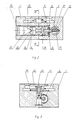
- Fig. 1 shows a longitudinal section of the distribution valve
- Fig. 2 shows section A-A marked in Fig. 1
- Fig. 3 shows section B-B marked in Fig. 2.
- the hydraulic distribution valve according to this present invention consists of body 1 inside which there is spherical closing component 4 provided with two grooves 17, 21 perpendicular to each other. Groove 17 is parallel to the longitudinal axis of lever 6 and groove 21 is perpendicular to the longitudinal axis of lever 7. The end of control lever 6 is placed inside groove 17.
- Height H of groove 21 is smaller than radius R of spherical closing component 4 whereas height L of groove 17 is at least equal to the sum of radius R of ball 4 and half dimension d of the larger side of lever 6 in its transversal section, that is, L ⁇ R + 1/2 d.
- Groove 21 is used for controlling, that is, it connects the hydraulic cylinder to a delivery pipe or a drain pipe.
- Closing component 4 is accommodated inside bush 3 between two seats 2, 5.
- Seat 2 is permanently sealed with seal 16 pressing bush 3 to a recess in the hole of body 1.
- Body 1 has made therein canal A connected to the drain pipe, canal B connected to the hydraulic cylinder, and canal C connected to the delivery pipe.
- Lever 6 is provided with crank 18 and pin 11 mounted in tappet 13 transversely to the axis of lever 6. Tappet 13 is brought in plane motion by means of push button 12. The plane motion of tappet 13 is obtained by means of spring 14. Lever 6 is sealed in hole 19 with sealing rings 8, 9 using sealing screw 10. The free end of lever 6 has a larger diameter, so that cone 22 of screw 10 should engage its groove 20. Depressing push button 12 causes spring 14 to deflect and tappet 13 to move downwards. Tappet 13 moving downwards engages pin 11 and, by means of crank 18, causes control lever 6 to rotate. Control lever 6 rotates spherical closing component 4 through a slight angle, thereby connecting delivery canal C to canal B connected to the hydraulic cylinder.
- spring 14 causes tappet 13 to return to its original position and engages closing component 4.
- Closing component 4 cuts off now canal B from canal C and, simultaneously, connects canal B to canal A connected to the drain pipe.
Landscapes
- Engineering & Computer Science (AREA)
- General Engineering & Computer Science (AREA)
- Mechanical Engineering (AREA)
- Taps Or Cocks (AREA)
Applications Claiming Priority (4)
| Application Number | Priority Date | Filing Date | Title |
|---|---|---|---|
| PL265513 | 1987-05-05 | ||
| PL26551387A PL265513A1 (en) | 1987-05-05 | 1987-05-05 | Three-way distributor valve |
| PL265569 | 1987-05-06 | ||
| PL26556987A PL155018B1 (pl) | 1987-05-06 | 1987-05-06 | Sterow nik hydrauliczny |
Publications (2)
| Publication Number | Publication Date |
|---|---|
| EP0296330A2 true EP0296330A2 (fr) | 1988-12-28 |
| EP0296330A3 EP0296330A3 (fr) | 1990-01-17 |
Family
ID=26653034
Family Applications (1)
| Application Number | Title | Priority Date | Filing Date |
|---|---|---|---|
| EP88106426A Withdrawn EP0296330A3 (fr) | 1987-05-05 | 1988-04-21 | Soupape de distribution à trois voies |
Country Status (1)
| Country | Link |
|---|---|
| EP (1) | EP0296330A3 (fr) |
Cited By (5)
| Publication number | Priority date | Publication date | Assignee | Title |
|---|---|---|---|---|
| CN106567943A (zh) * | 2016-10-15 | 2017-04-19 | 重庆比速汽车有限公司 | 压差式三通阀 |
| CN106640823A (zh) * | 2017-02-24 | 2017-05-10 | 太原理工大学 | 一种弹簧式液压脉冲阀及其使用方法 |
| CN106704285A (zh) * | 2017-02-24 | 2017-05-24 | 太原理工大学 | 一种液压压紧式液压脉冲阀及其使用方法 |
| CN106704284A (zh) * | 2017-02-24 | 2017-05-24 | 太原理工大学 | 一种蓄能器式液压脉冲阀及其使用方法 |
| CN106762915A (zh) * | 2017-02-24 | 2017-05-31 | 太原理工大学 | 一种容腔式液压脉冲阀及其使用方法 |
Family Cites Families (3)
| Publication number | Priority date | Publication date | Assignee | Title |
|---|---|---|---|---|
| US3628570A (en) * | 1970-11-20 | 1971-12-21 | Andis Allen R | Omnidirectional fluid-control valve |
| US4282899A (en) * | 1978-10-20 | 1981-08-11 | Dunckhorst William H | Timed shower head valve |
| DE3001837A1 (de) * | 1979-11-02 | 1981-05-14 | Fail Safe Industries, Inc., Lantana, Fla. | Abgedichtetes mehrfunktions-hochdruckventil |
-
1988
- 1988-04-21 EP EP88106426A patent/EP0296330A3/fr not_active Withdrawn
Cited By (7)
| Publication number | Priority date | Publication date | Assignee | Title |
|---|---|---|---|---|
| CN106567943A (zh) * | 2016-10-15 | 2017-04-19 | 重庆比速汽车有限公司 | 压差式三通阀 |
| CN106640823A (zh) * | 2017-02-24 | 2017-05-10 | 太原理工大学 | 一种弹簧式液压脉冲阀及其使用方法 |
| CN106704285A (zh) * | 2017-02-24 | 2017-05-24 | 太原理工大学 | 一种液压压紧式液压脉冲阀及其使用方法 |
| CN106704284A (zh) * | 2017-02-24 | 2017-05-24 | 太原理工大学 | 一种蓄能器式液压脉冲阀及其使用方法 |
| CN106762915A (zh) * | 2017-02-24 | 2017-05-31 | 太原理工大学 | 一种容腔式液压脉冲阀及其使用方法 |
| CN106704284B (zh) * | 2017-02-24 | 2018-03-09 | 太原理工大学 | 一种蓄能器式液压脉冲阀及其使用方法 |
| CN106762915B (zh) * | 2017-02-24 | 2018-03-09 | 太原理工大学 | 一种容腔式液压脉冲阀及其使用方法 |
Also Published As
| Publication number | Publication date |
|---|---|
| EP0296330A3 (fr) | 1990-01-17 |
Similar Documents
| Publication | Publication Date | Title |
|---|---|---|
| US6471181B2 (en) | Suspension of a valve plate of a vacuum valve | |
| US4880032A (en) | Multiple port valve | |
| CN100369714C (zh) | 电动液压式挤压装置及其工作方法 | |
| US3827313A (en) | Miniaturized joystick and cam structure with push button switch operating means | |
| US3030068A (en) | Ball valve | |
| JPH10193274A (ja) | トルクレンチ | |
| US20030034468A1 (en) | On-off valves for high pressure fluids | |
| EP0296330A2 (fr) | Soupape de distribution à trois voies | |
| JPH0631650B2 (ja) | スプ−ルタイプ切換弁装置 | |
| US3460799A (en) | Variable torque valve actuator | |
| EP1566552B1 (fr) | Verin a pression fluidique | |
| US3118695A (en) | Shaft clamping devices | |
| US5590991A (en) | Locking device | |
| US2962074A (en) | Pneumatically operated compressing tool | |
| DE838621T1 (de) | Knebelbetägtigtes Ventil | |
| WO1997013398A3 (fr) | Systemes d'appareils de robinetterie rotatifs metal-metal sans joints | |
| US4174825A (en) | Ball valve with reciprocal and rotatable spindle | |
| US4694862A (en) | Valve for attachment to an actuating means | |
| US4351362A (en) | Rotary valve | |
| US3795384A (en) | Valve with axially movable valving tube and laterally movable valving wall | |
| US6499568B1 (en) | Locking device | |
| CA2132172A1 (fr) | Clapet de commande pour compresseur a palettes a debit variable | |
| EP0436770B1 (fr) | Vanne à tiroir non glissant pour ultravide | |
| EP0241629A2 (fr) | Robinet vanne avec garniture | |
| US4413805A (en) | Valve detent |
Legal Events
| Date | Code | Title | Description |
|---|---|---|---|
| PUAI | Public reference made under article 153(3) epc to a published international application that has entered the european phase |
Free format text: ORIGINAL CODE: 0009012 |
|
| AK | Designated contracting states |
Kind code of ref document: A2 Designated state(s): AT DE GB |
|
| PUAL | Search report despatched |
Free format text: ORIGINAL CODE: 0009013 |
|
| AK | Designated contracting states |
Kind code of ref document: A3 Designated state(s): AT DE GB |
|
| STAA | Information on the status of an ep patent application or granted ep patent |
Free format text: STATUS: THE APPLICATION IS DEEMED TO BE WITHDRAWN |
|
| 18D | Application deemed to be withdrawn |
Effective date: 19900718 |