EP0296356A2 - Machine d'emballage, spécialement pour cigarettes - Google Patents
Machine d'emballage, spécialement pour cigarettes Download PDFInfo
- Publication number
- EP0296356A2 EP0296356A2 EP88107906A EP88107906A EP0296356A2 EP 0296356 A2 EP0296356 A2 EP 0296356A2 EP 88107906 A EP88107906 A EP 88107906A EP 88107906 A EP88107906 A EP 88107906A EP 0296356 A2 EP0296356 A2 EP 0296356A2
- Authority
- EP
- European Patent Office
- Prior art keywords
- working
- bobbin
- transport
- pin
- transport arm
- Prior art date
- Legal status (The legal status is an assumption and is not a legal conclusion. Google has not performed a legal analysis and makes no representation as to the accuracy of the status listed.)
- Granted
Links
Images




Classifications
-
- B—PERFORMING OPERATIONS; TRANSPORTING
- B65—CONVEYING; PACKING; STORING; HANDLING THIN OR FILAMENTARY MATERIAL
- B65H—HANDLING THIN OR FILAMENTARY MATERIAL, e.g. SHEETS, WEBS, CABLES
- B65H19/00—Changing the web roll
- B65H19/10—Changing the web roll in unwinding mechanisms or in connection with unwinding operations
- B65H19/12—Lifting, transporting, or inserting the web roll; Removing empty core
- B65H19/123—Lifting, transporting, or inserting the web roll; Removing empty core with cantilever supporting arrangements
-
- B—PERFORMING OPERATIONS; TRANSPORTING
- B65—CONVEYING; PACKING; STORING; HANDLING THIN OR FILAMENTARY MATERIAL
- B65B—MACHINES, APPARATUS OR DEVICES FOR, OR METHODS OF, PACKAGING ARTICLES OR MATERIALS; UNPACKING
- B65B41/00—Supplying or feeding container-forming sheets or wrapping material
- B65B41/12—Feeding webs from rolls
-
- B—PERFORMING OPERATIONS; TRANSPORTING
- B65—CONVEYING; PACKING; STORING; HANDLING THIN OR FILAMENTARY MATERIAL
- B65H—HANDLING THIN OR FILAMENTARY MATERIAL, e.g. SHEETS, WEBS, CABLES
- B65H2301/00—Handling processes for sheets or webs
- B65H2301/40—Type of handling process
- B65H2301/41—Winding, unwinding
- B65H2301/413—Supporting web roll
- B65H2301/4132—Cantilever arrangement
- B65H2301/41322—Cantilever arrangement pivoting movement of roll support
- B65H2301/413223—Cantilever arrangement pivoting movement of roll support around an axis parallel to roll axis
-
- B—PERFORMING OPERATIONS; TRANSPORTING
- B65—CONVEYING; PACKING; STORING; HANDLING THIN OR FILAMENTARY MATERIAL
- B65H—HANDLING THIN OR FILAMENTARY MATERIAL, e.g. SHEETS, WEBS, CABLES
- B65H2301/00—Handling processes for sheets or webs
- B65H2301/40—Type of handling process
- B65H2301/41—Winding, unwinding
- B65H2301/413—Supporting web roll
- B65H2301/4132—Cantilever arrangement
- B65H2301/41324—Cantilever arrangement linear movement of roll support
- B65H2301/413243—Cantilever arrangement linear movement of roll support parallel to roll axis
-
- B—PERFORMING OPERATIONS; TRANSPORTING
- B65—CONVEYING; PACKING; STORING; HANDLING THIN OR FILAMENTARY MATERIAL
- B65H—HANDLING THIN OR FILAMENTARY MATERIAL, e.g. SHEETS, WEBS, CABLES
- B65H2301/00—Handling processes for sheets or webs
- B65H2301/40—Type of handling process
- B65H2301/41—Winding, unwinding
- B65H2301/417—Handling or changing web rolls
- B65H2301/4171—Handling web roll
- B65H2301/4172—Handling web roll by circumferential portion, e.g. rolling on circumference
-
- B—PERFORMING OPERATIONS; TRANSPORTING
- B65—CONVEYING; PACKING; STORING; HANDLING THIN OR FILAMENTARY MATERIAL
- B65H—HANDLING THIN OR FILAMENTARY MATERIAL, e.g. SHEETS, WEBS, CABLES
- B65H2301/00—Handling processes for sheets or webs
- B65H2301/40—Type of handling process
- B65H2301/41—Winding, unwinding
- B65H2301/417—Handling or changing web rolls
- B65H2301/4171—Handling web roll
- B65H2301/4173—Handling web roll by central portion, e.g. gripping central portion
-
- B—PERFORMING OPERATIONS; TRANSPORTING
- B65—CONVEYING; PACKING; STORING; HANDLING THIN OR FILAMENTARY MATERIAL
- B65H—HANDLING THIN OR FILAMENTARY MATERIAL, e.g. SHEETS, WEBS, CABLES
- B65H2301/00—Handling processes for sheets or webs
- B65H2301/40—Type of handling process
- B65H2301/41—Winding, unwinding
- B65H2301/417—Handling or changing web rolls
- B65H2301/4171—Handling web roll
- B65H2301/41745—Handling web roll by axial movement of roll
-
- Y—GENERAL TAGGING OF NEW TECHNOLOGICAL DEVELOPMENTS; GENERAL TAGGING OF CROSS-SECTIONAL TECHNOLOGIES SPANNING OVER SEVERAL SECTIONS OF THE IPC; TECHNICAL SUBJECTS COVERED BY FORMER USPC CROSS-REFERENCE ART COLLECTIONS [XRACs] AND DIGESTS
- Y10—TECHNICAL SUBJECTS COVERED BY FORMER USPC
- Y10S—TECHNICAL SUBJECTS COVERED BY FORMER USPC CROSS-REFERENCE ART COLLECTIONS [XRACs] AND DIGESTS
- Y10S414/00—Material or article handling
- Y10S414/124—Roll handlers
Definitions
- the invention relates to a packaging machine for the production of (cigarette) packaging from web-shaped packaging material which is pulled from a (work) bobbin onto a work spigot, a new "full" bobbin being taken from a bobbin stock by a transport spigot, in axial alignment conveyed in front of the working pin and transferred to it by axial displacement.
- High-performance packaging machines especially cigarette packaging machines, have a correspondingly high consumption of packaging material. This is - aside from the feeding of otherwise manufactured individual blanks - as a web-like material in wound bobbins made available to the packaging machine. From this, blanks are then manufactured and processed within the packaging machine.
- a rocker arm with transport pin can be moved along a straight conveying path by a spindle drive.
- the rocker arm is pivoted with the bobbin transversely to the conveying plane (DE-OS 32 02 647).
- the invention has for its object to design the bobbin changing device in a packaging machine for processing bobbins of sheet-like packaging material so that expired, "empty” (working) bobbins can be exchanged for new, “full” bobbins within a very short time without that the operation of the packaging machine must be interrupted.
- the packaging machine according to the invention or its bobbin changing device is characterized in that the transport pin on one Transport arm is arranged, which is pivotally mounted above the working pin and each promotes a ("full") bobbin along a circular arc alternatively in front of one of several, in particular two, working pins.
- two working pins are provided in the packaging machine according to the invention, preferably lying next to one another at a distance in a common horizontal plane.
- the sheet-like packaging material is pulled off one of the two working pins to produce blanks.
- the other is ready to change an empty bobbin for a "full" bobbin.
- the transfer of the same from a bobbin stock takes place according to the invention by a pivotable transport arm which is mounted relative to the working spigot that the new bobbin can be conveyed in front of one or the other working spigot by short pivoting movements.
- the transfer is expediently carried out by hand, since the transport pin and the working pin are aligned on the same axis and only a very short axially directed conveying path has to be overcome.
- the bobbin stock in particular a trough-shaped, elongated support frame, is preferably arranged above the working spigot, namely above the other structural parts of the packaging machine, the stocked bobbins being axially aligned.
- the support frame can be easily loaded with new bobbins from the back of the packaging machine.
- the transport arm as a transfer element for the "full" bobbins from the supply to the working spigot is mounted centrally between the transport spigots, so that short swiveling movements to one side and the other allow the bobbins to be delivered.
- the transport arm slidable in the axial direction with the transport pin for taking over the bobbin from the supply set back from the working pin.
- the present bobbin changing device is an integral part of a packaging machine 10, in particular for the production of cigarette packaging.
- sheet-like packaging material is processed, e.g. Tinfoil, paper or plastic film.
- the packaging material is provided in the form of bobbins 11.
- the material web is drawn off from a work reel 12 and processed to produce blanks.
- two working pins 13, 14 are provided for receiving work bobbins 12, which are mounted on a machine frame 15 at a distance from one another in a common horizontal plane.
- the working pins 13, 14 are freely cantilevered, supported on one side and driven in rotation within the machine frame 15 by organs (not shown).
- the bobbins 11 or work bobbins 12 are provided with a center hole 16 which matches the dimensions of the work pins 13, 14, so that the bobbins 11 or work bobbins 12 can be pushed onto the work pins 13, 14 in the axial direction.
- the bobbins 11, 12 are usually provided with a bobbin core in the form of a cardboard sleeve (not shown in more detail), which is (manually) drawn off from the working pin 13, 14 after a working bobbin 12 has been used up.
- a working bobbin 12 has been used up.
- One of the working pins 13, 14 is in the working position.
- the packaging material is drawn off from this as material web 17 (working pin 14 in FIG. 4), while the other working pin 13 is provided for receiving or holding a new, "full" bobbin 11.
- a packaging stock 18 is associated with the packaging machine 10 or the bobbin changing device. In the present exemplary embodiment, this is arranged above the packaging machine 10 or above the machine frame 15.
- the bobbin stock 18 consists essentially of an elongated support frame 19 which extends horizontally across the longitudinal extent of the packaging machine 10. The majority of the support frame 19 is located on the back of the packaging machine 10, 3 with a support 20 at the free end.
- a large number of bobbins 11 are arranged on the support frame 19 in parallel planes and in axial alignment, the bobbins 11 standing up on the support frame 19 with their peripheral surface at the bottom.
- a bobbin 11a which is in front or closest to the work pin 13, is ready for removal and delivery to one of the work pins 13, 14.
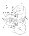
- a transport arm 21 is used as the transport member for taking over a bobbin 11a from the bobbin supply 18 and for transferring it to one of the two working pins 13, 14.
- a free-standing, one-sided mounted transport pin 22 is attached to this in the upper area, which also belongs to the Dimensions of the center hole 16 fits.
- the transport arm 21 is mounted and driven in a special way.
- the reel stock 18 is offset from the vertical rotational plane of the work reels 12 to the rear of the packaging machine.
- the transport arm 21 can therefore be moved in the axial direction of the transport pin 22, so that it can accommodate the bobbin 11a by entering the center hole 16 thereof.
- the transport arm 21 With the bobbin 11a held on the transport pin 22, the transport arm 21 is moved in the opposite direction until the bobbin 11a is located in one plane in front of the work bobbins 12 or the work pins 13, 14. By pivoting the transport arm 21 in this plane along a quarter-circle arc, the bobbin 11a is moved in front of one or the other of the working pins 13, 14, specifically in the axial direction. In this position, the bobbin 11a is transferred to the empty work pin by axial displacement, as shown in FIG. 2 with the help of the work pin 13. The transfer is advantageously carried out manually.
- the transport arm 21 is now pivoted back from the horizontally directed transfer position (FIG. 2) into the upright middle position (FIGS. 3, 4). By shifting in the axial direction, the transport pin 22 is moved in the direction of the reel stock 18 for taking over the next reel 11a.
- the transport arm 21 is mounted on an actuating frame 23 for carrying out the movements described, which is shown in FIG. 2 as an axially displaceable and rotatable rod.
- the actuating frame 23 consists of an elongated support rod 24 which is axially displaceably mounted in the machine frame 15.
- the horizontally directed support rod 24 is partially cylindrical in the upper cross-sectional area and provided with a lower rectangular extension 25.
- the latter is designed as a rack 26 on the underside. This is in engagement with a pinion 27 which can be driven in a rotating manner in one direction or the other via a drive shaft 28 (FIG. 4) by a motor (not shown here).
- the support rod 24 is formed at its ends with upward support legs 29, 30. Ends of a rotary rod 31 are rotatably mounted in these. A free bearing end 32 - on the side of the machine frame 15 facing the working pin 13, 14 - is guided through the support leg 29 and connected to a lower region of the transport arm 21. A rotary movement of the rotary rod 31 about its own longitudinal axis accordingly results in a corresponding pivoting movement of the transport arm 21 in one direction or the other.
- the rotary rod 31 is axially displaceable but non-rotatably mounted in a guide sleeve 33 in the machine frame 15.
- the rotationally fixed guidance of the rotary rod 31 in the guide sleeve 33 is here by grooves and tongues (Fig. 4) causes.
- the guide sleeve 33 is in turn rotatable, but axially immovable in the machine frame 15.
- a gearwheel 34 is arranged on an end of the guide sleeve 33 protruding from the machine frame 15. This is driven in rotation via an intermediate gear 35 by a drive motor 36 with pinion 37.
- the intermediate gear 35 is rotatably mounted as a toothed ring on a shoulder 38 of the machine frame 15.
- the support rod 24 passes through the hollow extension 38.
- the transport arm 21 is accordingly pivoted in one direction or the other by reversible drive of the drive motor 36, specifically by means of a corresponding rotary drive of the rotary rod 31. This is mounted here centrally between the working pins 13, 14, at the same height as these.
- the support frame 19 for the bobbin stock 18 is designed such that an elevated end stop 39 is formed on the front removal side for the bobbin 11a.
- the front bobbin 11a must therefore first be raised slightly before it can be removed from the support frame 19.
- the transport pin 22 is adjustably mounted on the transport arm 21, in the longitudinal direction of the transport arm 21. This also makes possible settings to different positions of the working pins 13 and 14 possible.
- the transport pin 22 is attached to a support body 40 which can be moved along a fixed guide without tilting within the transport arm 21 which is open on one side and is designed as a hollow body.
- the guide here consists of lateral guide rods 42 fixedly attached to side walls 41. These consist of round material. Support rollers 43, 44 attached to the supporting body 40 bear positively on the guide rods 42 with curved running surfaces.
- the support body 40 is provided with four such support rollers 43, 44, each of which rests in pairs on a guide rod 42.
- a spindle 45 is rotatably mounted therein. This is driven in rotation by a servo motor 46 also mounted within the transport arm 21.
- the support body 40 is mounted on the spindle 45 with a projection serving as a spindle nut 47.
- the transport arm 21 is therefore first threaded into the bobbin 11a with the free transport pin 22.
- the transport pin 22 is then adjusted in the longitudinal direction of the transport arm 21, that is to say moved upwards, as a result of which the bobbin is lifted out of the support frame 19 and is thus released.
- the transport arm 21 is adjusted by appropriate drive of the pinion 27 to the pivoting plane in front of the plane of the working pins 13, 14 and the transport pin 22 is aligned with the axially aligned position of the working pin 13, 14 to be loaded.
- the described pivoting movement of the transport arm 21 takes place.
- the adjusting movement of the transport pin 22 can also take place after the pivoting movement of the transport arm 21.
- the support frame 19 for the bobbin stock 18 is also designed in a special way, namely in such a way that the bobbins 11 are automatically and gently conveyed to the end of removal in a gentle manner.
- the support frame 19 consists of several, in the present case two, elongated, rotatably driven support rollers 48, 49. These are directed in the longitudinal direction of the support frame 19 and serve as support and support members for the bobbins 11, 11a. In the direction of the removal side, the support rollers 48, 49 slightly diverging, at a very acute angle.
- the (rectified) rotary drive of the support rollers 48, 49 has the effect that the bobbins 11, 11a given on the back are always conveyed towards one another in the direction of the end stop 39 up to the sealing position.
- the support rollers 48, 49 are driven by a motor 50 for this purpose.
- the facing ends of the support rollers 48, 49 are gearingly connected to one another by an enveloping drive, in particular by a toothed belt 51.
Landscapes
- Engineering & Computer Science (AREA)
- Mechanical Engineering (AREA)
- Replacement Of Web Rolls (AREA)
- Wrapping Of Specific Fragile Articles (AREA)
- Supplying Of Containers To The Packaging Station (AREA)
Priority Applications (1)
| Application Number | Priority Date | Filing Date | Title |
|---|---|---|---|
| EP92116860A EP0521538B1 (fr) | 1987-06-26 | 1988-05-18 | Machine d'emballage, spécialement pour cigarettes |
Applications Claiming Priority (2)
| Application Number | Priority Date | Filing Date | Title |
|---|---|---|---|
| DE19873721091 DE3721091A1 (de) | 1987-06-26 | 1987-06-26 | Verpackungsmaschine, insbesondere fuer zigaretten |
| DE3721091 | 1987-06-26 |
Related Child Applications (1)
| Application Number | Title | Priority Date | Filing Date |
|---|---|---|---|
| EP92116860.5 Division-Into | 1992-10-02 |
Publications (3)
| Publication Number | Publication Date |
|---|---|
| EP0296356A2 true EP0296356A2 (fr) | 1988-12-28 |
| EP0296356A3 EP0296356A3 (en) | 1990-03-21 |
| EP0296356B1 EP0296356B1 (fr) | 1993-08-11 |
Family
ID=6330329
Family Applications (2)
| Application Number | Title | Priority Date | Filing Date |
|---|---|---|---|
| EP92116860A Expired - Lifetime EP0521538B1 (fr) | 1987-06-26 | 1988-05-18 | Machine d'emballage, spécialement pour cigarettes |
| EP88107906A Expired - Lifetime EP0296356B1 (fr) | 1987-06-26 | 1988-05-18 | Machine d'emballage, spécialement pour cigarettes |
Family Applications Before (1)
| Application Number | Title | Priority Date | Filing Date |
|---|---|---|---|
| EP92116860A Expired - Lifetime EP0521538B1 (fr) | 1987-06-26 | 1988-05-18 | Machine d'emballage, spécialement pour cigarettes |
Country Status (6)
| Country | Link |
|---|---|
| US (2) | US4896842A (fr) |
| EP (2) | EP0521538B1 (fr) |
| JP (1) | JP2553640B2 (fr) |
| BR (1) | BR8803124A (fr) |
| CA (1) | CA1294525C (fr) |
| DE (3) | DE3721091A1 (fr) |
Cited By (5)
| Publication number | Priority date | Publication date | Assignee | Title |
|---|---|---|---|---|
| EP0391117A1 (fr) * | 1989-04-05 | 1990-10-10 | SASIB S.p.A. | Dispositif automatique pour l'alimentation en bande de matériel à envelopper, spécialement bobines de papier à cigarettes |
| FR2655963A1 (fr) * | 1989-12-18 | 1991-06-21 | Gd Spa | Procede et dispositif d'alimentation et de chargement de bobines sur une machine d'un processus de fabrication. |
| EP0469298A1 (fr) * | 1990-07-31 | 1992-02-05 | Focke & Co. (GmbH & Co.) | Dispositif d'alimentation de machines d'emballage en matériau d'emballage |
| EP0820944A1 (fr) * | 1996-07-03 | 1998-01-28 | G.D Societa' Per Azioni | Unité d'alimentation de matériau d'emballage |
| CN101734503B (zh) * | 2009-11-07 | 2012-11-14 | 浙江超伟机械有限公司 | 连卷袋自动收换卷机构 |
Families Citing this family (19)
| Publication number | Priority date | Publication date | Assignee | Title |
|---|---|---|---|---|
| DE3721091A1 (de) * | 1987-06-26 | 1989-01-05 | Focke & Co | Verpackungsmaschine, insbesondere fuer zigaretten |
| DE3812514C2 (de) * | 1988-04-15 | 1998-01-29 | Focke & Co | Verpackungsmaschine mit einem an einem Transportarm angeordneten Transportzapfen für neue Bobinen |
| DE3827917C2 (de) * | 1988-06-18 | 1998-07-09 | Focke & Co | Vorrichtung zum Transport von Verpackungsmaterial zu einer Verpackungsmaschine |
| EP0347586B1 (fr) * | 1988-06-18 | 1993-12-08 | Focke & Co. (GmbH & Co.) | Dispositif pour transporter une matière d'emballage dans une machine d'emballage |
| IT1242891B (it) * | 1990-12-24 | 1994-05-18 | Gd Spa | Metodo e dispositivo per il cambio di bobine in una macchina utilizzatrice di materiale in nastro. |
| IT1253017B (it) * | 1991-09-11 | 1995-07-10 | Gd Spa | Dispositivo per l'alimentazione di prodotti disposti in serie ad una successivia stazione operativa |
| IT1253272B (it) * | 1991-10-10 | 1995-07-14 | Gd Spa | Dispositivo per la sostituzione di bobine di materiale in nastro in una macchina operatrice |
| DE4221052A1 (de) * | 1992-06-30 | 1994-01-05 | Focke & Co | Vorrichtung zum Handhaben von Bobinen aus Materialbahnen |
| IT1299847B1 (it) * | 1998-02-17 | 2000-04-04 | Gd Spa | Metodo e dispositivo per l'alimentazione di bobine. |
| FI104889B (fi) * | 1998-03-05 | 2000-04-28 | Valmet Corp | Menetelmä ja sovitelma käärerullien vaihtamiseksi rullankäärintälaitteessa |
| DE19847160A1 (de) * | 1998-10-13 | 2000-04-20 | Hauni Maschinenbau Ag | Bobinenwechsler |
| US6494400B1 (en) * | 2000-10-25 | 2002-12-17 | Illinois Tool Works Inc. | Automatic film roll changer and method of operating the same |
| JP2006199488A (ja) * | 2005-01-24 | 2006-08-03 | Ishida Co Ltd | 包装機 |
| KR101369516B1 (ko) * | 2013-06-03 | 2014-03-04 | 김형곤 | 정방향 회전과 역방향 회전을 반복하는 이송관을 구비하는 재료 포장장치 및, 이를 이용한 재료 포장방법 |
| JP6466751B2 (ja) * | 2015-03-19 | 2019-02-06 | 株式会社イシダ | フィルムロール支持装置 |
| WO2017062981A1 (fr) * | 2015-10-10 | 2017-04-13 | Wilt Robert R | Transporteur à disques pour capsules d'échantillon et autres |
| IT201700045784A1 (it) * | 2017-04-27 | 2018-10-27 | Ri Flex Abrasives S R L | Dispositivo alimentatore di bobine |
| KR102370489B1 (ko) * | 2019-12-09 | 2022-03-07 | 삼일테크(주) | 반도체 패키지 자동 포장장치 |
| US12434934B2 (en) * | 2019-12-24 | 2025-10-07 | Wuxi Lead Intelligent Equipment Co., Ltd. | Automatic roll replacing device, and winding equipment |
Family Cites Families (18)
| Publication number | Priority date | Publication date | Assignee | Title |
|---|---|---|---|---|
| US1652419A (en) * | 1925-07-07 | 1927-12-13 | Hastings M Shields | Conveyer |
| US1946453A (en) * | 1933-08-18 | 1934-02-06 | Mathews Conveyer Co | Conveying mechanism |
| DE1108239B (de) * | 1960-02-17 | 1961-06-08 | Koenig & Bauer Schnellpressfab | Papierrollenwechselvorrichtung, insbesondere fuer Rotationsdruckmaschinen |
| US3163282A (en) * | 1963-01-30 | 1964-12-29 | Shropshire Sampson & Stollenwe | Apparatus for and method of feeding apples for coring and peeling thereof |
| US3503486A (en) * | 1968-06-07 | 1970-03-31 | Gulf Oil Corp | Lid conveyor system |
| US4040513A (en) * | 1972-11-20 | 1977-08-09 | Lewals, Inc. | Disc advancing and metering device |
| DE2259300C2 (de) * | 1972-12-04 | 1984-01-05 | Degussa Ag, 6000 Frankfurt | Fördervorrichtung zum Transport von Förderbändern, Drahtgliedergurten oder Förderkästen in einem Wärmebehandlungsofen |
| US4281621A (en) * | 1976-11-26 | 1981-08-04 | Rockcor, Inc. | Tire sealant applicator |
| IT1145030B (it) * | 1981-02-25 | 1986-11-05 | Gd Spa | Dispositivo per l'alimentazione automatica di bobine ad una macchina operatrice |
| DE3342204A1 (de) * | 1983-11-23 | 1985-05-30 | Focke & Co, 2810 Verden | Verpackungsmaschine mit vorratshalter fuer bobinen |
| IT1179255B (it) * | 1984-01-25 | 1987-09-16 | Gd Spa | Dispositivo di alimentazione automatica di bobine di materiale d'incarto ad una macchina utilizzatrice |
| JPS60135842U (ja) * | 1984-02-17 | 1985-09-09 | ソニー株式会社 | テ−プ案内ドラムのリ−ド装置 |
| DE3436217A1 (de) * | 1984-10-03 | 1986-04-03 | Focke & Co (GmbH & Co), 2810 Verden | Verfahren und vorrichtung zum wechseln von bobinen in verbindung mit verpackungsmaschinen |
| DE3534771C2 (de) * | 1984-11-16 | 1995-09-21 | Hauni Werke Koerber & Co Kg | Bobinenwechseleinheit für Maschinen der tabakverarbeitenden Industrie |
| JPS61123416A (ja) * | 1984-11-20 | 1986-06-11 | Yamada Dobby Co Ltd | 巻取り機 |
| DE3519580C1 (en) * | 1985-05-31 | 1987-03-05 | Bat Cigarettenfab Gmbh | Installation for manufacturing and packaging cigarettes |
| DE3631205A1 (de) * | 1986-09-13 | 1988-03-24 | Focke & Co | Vorrichtung zur zufuehrung von verpackungsmaterial-bobinen zu einer verpackungsmaschine |
| DE3721091A1 (de) * | 1987-06-26 | 1989-01-05 | Focke & Co | Verpackungsmaschine, insbesondere fuer zigaretten |
-
1987
- 1987-06-26 DE DE19873721091 patent/DE3721091A1/de not_active Withdrawn
-
1988
- 1988-05-18 DE DE8888107906T patent/DE3883091D1/de not_active Expired - Fee Related
- 1988-05-18 EP EP92116860A patent/EP0521538B1/fr not_active Expired - Lifetime
- 1988-05-18 EP EP88107906A patent/EP0296356B1/fr not_active Expired - Lifetime
- 1988-05-18 DE DE3855815T patent/DE3855815D1/de not_active Expired - Fee Related
- 1988-06-22 CA CA000570147A patent/CA1294525C/fr not_active Expired - Lifetime
- 1988-06-23 US US07/210,431 patent/US4896842A/en not_active Expired - Lifetime
- 1988-06-24 JP JP63155075A patent/JP2553640B2/ja not_active Expired - Fee Related
- 1988-06-24 BR BR8803124A patent/BR8803124A/pt not_active IP Right Cessation
-
1991
- 1991-04-04 US US07/681,460 patent/US5135103A/en not_active Expired - Fee Related
Cited By (6)
| Publication number | Priority date | Publication date | Assignee | Title |
|---|---|---|---|---|
| EP0391117A1 (fr) * | 1989-04-05 | 1990-10-10 | SASIB S.p.A. | Dispositif automatique pour l'alimentation en bande de matériel à envelopper, spécialement bobines de papier à cigarettes |
| FR2655963A1 (fr) * | 1989-12-18 | 1991-06-21 | Gd Spa | Procede et dispositif d'alimentation et de chargement de bobines sur une machine d'un processus de fabrication. |
| EP0469298A1 (fr) * | 1990-07-31 | 1992-02-05 | Focke & Co. (GmbH & Co.) | Dispositif d'alimentation de machines d'emballage en matériau d'emballage |
| US5205505A (en) * | 1990-07-31 | 1993-04-27 | Focke & Co. | Device for supplying packaging machines with packaging material |
| EP0820944A1 (fr) * | 1996-07-03 | 1998-01-28 | G.D Societa' Per Azioni | Unité d'alimentation de matériau d'emballage |
| CN101734503B (zh) * | 2009-11-07 | 2012-11-14 | 浙江超伟机械有限公司 | 连卷袋自动收换卷机构 |
Also Published As
| Publication number | Publication date |
|---|---|
| EP0521538A3 (en) | 1993-06-30 |
| EP0296356B1 (fr) | 1993-08-11 |
| JP2553640B2 (ja) | 1996-11-13 |
| BR8803124A (pt) | 1989-01-24 |
| DE3721091A1 (de) | 1989-01-05 |
| EP0521538A2 (fr) | 1993-01-07 |
| EP0296356A3 (en) | 1990-03-21 |
| JPS6438360A (en) | 1989-02-08 |
| US5135103A (en) | 1992-08-04 |
| DE3855815D1 (de) | 1997-04-10 |
| US4896842A (en) | 1990-01-30 |
| CA1294525C (fr) | 1992-01-21 |
| EP0521538B1 (fr) | 1997-03-05 |
| DE3883091D1 (de) | 1993-09-16 |
Similar Documents
| Publication | Publication Date | Title |
|---|---|---|
| EP0296356B1 (fr) | Machine d'emballage, spécialement pour cigarettes | |
| DE3812514C2 (de) | Verpackungsmaschine mit einem an einem Transportarm angeordneten Transportzapfen für neue Bobinen | |
| DE2402744C2 (de) | Automatische arbeitende Übergabe- und Transportvorrichtung für von einem Förderband angelieferte volle Garnspulen | |
| DE3241032C2 (fr) | ||
| DE4224609A1 (de) | Fördervorrichtung für Zigaretten | |
| DE2037006B2 (de) | Vorrichtung zum Zuführen und Einlegen von stangen- oder rohrförmigen Wickelkernen beim Wickelwechsel bei Tragwalzen-Wickelmaschinen | |
| EP0469298B1 (fr) | Dispositif d'alimentation de machines d'emballage en matériau d'emballage | |
| EP0261508A2 (fr) | Dispositif pour le transport de bobines de papier d'emballage vers les machines d'emballage | |
| DE3727888A1 (de) | Textilbahnausgabevorrichtung | |
| EP0150511A2 (fr) | Dispositif d'emballage d'objets, spécialement des cigarettes | |
| DE4428786A1 (de) | Vorrichtung zur Entnahme von Spulen aus einem Magazin und zur Übertragung derselben an eine Abwickeleinheit | |
| DE1710098A1 (de) | Abzugsvorrichtung fuer Spulmaschinen | |
| WO2017025155A1 (fr) | Dispositif de remplissage d'un pot de filature avec un ruban de fibres | |
| DE4106608C2 (de) | Vorrichtung zum Übergeben von Spulen | |
| DE1801593C3 (de) | Vorrichtung zur Übergabe von kontinuierlich zugeführten Gegenständen | |
| DE4317562C2 (de) | Magazin und Übergabevorrichtung für eine Anzahl von Rollen | |
| DE565372C (de) | Spulmaschine mit einem den Fadenablaufstellen entlang laufenden endlosen Foerdermittel | |
| EP0323608A2 (fr) | Machine d'emballage pour fabriquer des boîtes de cigarettes | |
| CH633326A5 (de) | Verfahren und spulenwechsler zum gruppenweisen auswechseln von vollspulen an einer spinnmaschine. | |
| DE2619366A1 (de) | Vorrichtung zum ausbringen stabfoermiger gegenstaende aus einem behaelter | |
| DE3613087A1 (de) | Vertikal angeordneter reibfinisseur | |
| DE1109603B (de) | Vorrichtung zum Zufuehren von aus einem Vorrat in ungeordnetem Zustand entnommenen Roehren, Staeben, Stangen od. dgl. | |
| DE2356884C3 (de) | Einlegevorrichtung | |
| DE2400081C3 (de) | Vorrichtung zum Zuführen von leeren Spulen für eine automatische vor Spinneinrichtungen längsbewegbare Spulenwechseleinrichtung | |
| DE806539C (de) | Maschine zum Falten von Kartonstuecken fuer Kartonbehaelter |
Legal Events
| Date | Code | Title | Description |
|---|---|---|---|
| PUAI | Public reference made under article 153(3) epc to a published international application that has entered the european phase |
Free format text: ORIGINAL CODE: 0009012 |
|
| AK | Designated contracting states |
Kind code of ref document: A2 Designated state(s): DE FR GB IT |
|
| PUAL | Search report despatched |
Free format text: ORIGINAL CODE: 0009013 |
|
| AK | Designated contracting states |
Kind code of ref document: A3 Designated state(s): DE FR GB IT |
|
| 17P | Request for examination filed |
Effective date: 19900920 |
|
| 17Q | First examination report despatched |
Effective date: 19921104 |
|
| GRAA | (expected) grant |
Free format text: ORIGINAL CODE: 0009210 |
|
| AK | Designated contracting states |
Kind code of ref document: B1 Designated state(s): DE FR GB IT |
|
| XX | Miscellaneous (additional remarks) |
Free format text: TEILANMELDUNG 92116860.5 EINGEREICHT AM 18/05/88. |
|
| GBT | Gb: translation of ep patent filed (gb section 77(6)(a)/1977) |
Effective date: 19930812 |
|
| REF | Corresponds to: |
Ref document number: 3883091 Country of ref document: DE Date of ref document: 19930916 |
|
| ITF | It: translation for a ep patent filed | ||
| ET | Fr: translation filed | ||
| PLBE | No opposition filed within time limit |
Free format text: ORIGINAL CODE: 0009261 |
|
| STAA | Information on the status of an ep patent application or granted ep patent |
Free format text: STATUS: NO OPPOSITION FILED WITHIN TIME LIMIT |
|
| 26N | No opposition filed | ||
| REG | Reference to a national code |
Ref country code: GB Ref legal event code: IF02 |
|
| PGFP | Annual fee paid to national office [announced via postgrant information from national office to epo] |
Ref country code: FR Payment date: 20030508 Year of fee payment: 16 |
|
| PGFP | Annual fee paid to national office [announced via postgrant information from national office to epo] |
Ref country code: DE Payment date: 20040423 Year of fee payment: 17 |
|
| PGFP | Annual fee paid to national office [announced via postgrant information from national office to epo] |
Ref country code: GB Payment date: 20040512 Year of fee payment: 17 |
|
| PG25 | Lapsed in a contracting state [announced via postgrant information from national office to epo] |
Ref country code: FR Free format text: LAPSE BECAUSE OF NON-PAYMENT OF DUE FEES Effective date: 20050131 |
|
| REG | Reference to a national code |
Ref country code: FR Ref legal event code: ST |
|
| PG25 | Lapsed in a contracting state [announced via postgrant information from national office to epo] |
Ref country code: IT Free format text: LAPSE BECAUSE OF NON-PAYMENT OF DUE FEES;WARNING: LAPSES OF ITALIAN PATENTS WITH EFFECTIVE DATE BEFORE 2007 MAY HAVE OCCURRED AT ANY TIME BEFORE 2007. THE CORRECT EFFECTIVE DATE MAY BE DIFFERENT FROM THE ONE RECORDED. Effective date: 20050518 Ref country code: GB Free format text: LAPSE BECAUSE OF NON-PAYMENT OF DUE FEES Effective date: 20050518 |
|
| PG25 | Lapsed in a contracting state [announced via postgrant information from national office to epo] |
Ref country code: DE Free format text: LAPSE BECAUSE OF NON-PAYMENT OF DUE FEES Effective date: 20051201 |
|
| GBPC | Gb: european patent ceased through non-payment of renewal fee |
Effective date: 20050518 |