EP0296367A2 - Dispositif automatique de changement d'outil - Google Patents
Dispositif automatique de changement d'outil Download PDFInfo
- Publication number
- EP0296367A2 EP0296367A2 EP88108249A EP88108249A EP0296367A2 EP 0296367 A2 EP0296367 A2 EP 0296367A2 EP 88108249 A EP88108249 A EP 88108249A EP 88108249 A EP88108249 A EP 88108249A EP 0296367 A2 EP0296367 A2 EP 0296367A2
- Authority
- EP
- European Patent Office
- Prior art keywords
- tool
- changing device
- clamping
- tool changing
- bit shaft
- Prior art date
- Legal status (The legal status is an assumption and is not a legal conclusion. Google has not performed a legal analysis and makes no representation as to the accuracy of the status listed.)
- Granted
Links
- 230000010354 integration Effects 0.000 claims 1
- 210000000078 claw Anatomy 0.000 description 1
- 238000010168 coupling process Methods 0.000 description 1
Images


Classifications
-
- B—PERFORMING OPERATIONS; TRANSPORTING
- B23—MACHINE TOOLS; METAL-WORKING NOT OTHERWISE PROVIDED FOR
- B23Q—DETAILS, COMPONENTS, OR ACCESSORIES FOR MACHINE TOOLS, e.g. ARRANGEMENTS FOR COPYING OR CONTROLLING; MACHINE TOOLS IN GENERAL CHARACTERISED BY THE CONSTRUCTION OF PARTICULAR DETAILS OR COMPONENTS; COMBINATIONS OR ASSOCIATIONS OF METAL-WORKING MACHINES, NOT DIRECTED TO A PARTICULAR RESULT
- B23Q3/00—Devices holding, supporting, or positioning work or tools, of a kind normally removable from the machine
- B23Q3/155—Arrangements for automatic insertion or removal of tools, e.g. combined with manual handling
- B23Q3/15513—Arrangements for automatic insertion or removal of tools, e.g. combined with manual handling the tool being taken from a storage device and transferred to a tool holder by means of transfer devices
-
- B—PERFORMING OPERATIONS; TRANSPORTING
- B23—MACHINE TOOLS; METAL-WORKING NOT OTHERWISE PROVIDED FOR
- B23Q—DETAILS, COMPONENTS, OR ACCESSORIES FOR MACHINE TOOLS, e.g. ARRANGEMENTS FOR COPYING OR CONTROLLING; MACHINE TOOLS IN GENERAL CHARACTERISED BY THE CONSTRUCTION OF PARTICULAR DETAILS OR COMPONENTS; COMBINATIONS OR ASSOCIATIONS OF METAL-WORKING MACHINES, NOT DIRECTED TO A PARTICULAR RESULT
- B23Q3/00—Devices holding, supporting, or positioning work or tools, of a kind normally removable from the machine
- B23Q3/155—Arrangements for automatic insertion or removal of tools, e.g. combined with manual handling
- B23Q3/1552—Arrangements for automatic insertion or removal of tools, e.g. combined with manual handling parts of devices for automatically inserting or removing tools
- B23Q3/15553—Tensioning devices or tool holders, e.g. grippers
-
- Y—GENERAL TAGGING OF NEW TECHNOLOGICAL DEVELOPMENTS; GENERAL TAGGING OF CROSS-SECTIONAL TECHNOLOGIES SPANNING OVER SEVERAL SECTIONS OF THE IPC; TECHNICAL SUBJECTS COVERED BY FORMER USPC CROSS-REFERENCE ART COLLECTIONS [XRACs] AND DIGESTS
- Y10—TECHNICAL SUBJECTS COVERED BY FORMER USPC
- Y10T—TECHNICAL SUBJECTS COVERED BY FORMER US CLASSIFICATION
- Y10T409/00—Gear cutting, milling, or planing
- Y10T409/30—Milling
- Y10T409/309352—Cutter spindle or spindle support
- Y10T409/309408—Cutter spindle or spindle support with cutter holder
- Y10T409/309464—Cutter spindle or spindle support with cutter holder and draw bar
-
- Y—GENERAL TAGGING OF NEW TECHNOLOGICAL DEVELOPMENTS; GENERAL TAGGING OF CROSS-SECTIONAL TECHNOLOGIES SPANNING OVER SEVERAL SECTIONS OF THE IPC; TECHNICAL SUBJECTS COVERED BY FORMER USPC CROSS-REFERENCE ART COLLECTIONS [XRACs] AND DIGESTS
- Y10—TECHNICAL SUBJECTS COVERED BY FORMER USPC
- Y10T—TECHNICAL SUBJECTS COVERED BY FORMER US CLASSIFICATION
- Y10T483/00—Tool changing
- Y10T483/17—Tool changing including machine tool or component
- Y10T483/1733—Rotary spindle machine tool [e.g., milling machine, boring, machine, grinding machine, etc.]
- Y10T483/1748—Tool changer between spindle and matrix
- Y10T483/1752—Tool changer between spindle and matrix including tool holder pivotable about axis
- Y10T483/1755—Plural tool holders pivotable about common axis
- Y10T483/1764—Tool holders pivotable about plural nonparallel axes
-
- Y—GENERAL TAGGING OF NEW TECHNOLOGICAL DEVELOPMENTS; GENERAL TAGGING OF CROSS-SECTIONAL TECHNOLOGIES SPANNING OVER SEVERAL SECTIONS OF THE IPC; TECHNICAL SUBJECTS COVERED BY FORMER USPC CROSS-REFERENCE ART COLLECTIONS [XRACs] AND DIGESTS
- Y10—TECHNICAL SUBJECTS COVERED BY FORMER USPC
- Y10T—TECHNICAL SUBJECTS COVERED BY FORMER US CLASSIFICATION
- Y10T483/00—Tool changing
- Y10T483/17—Tool changing including machine tool or component
- Y10T483/1733—Rotary spindle machine tool [e.g., milling machine, boring, machine, grinding machine, etc.]
- Y10T483/1748—Tool changer between spindle and matrix
- Y10T483/1752—Tool changer between spindle and matrix including tool holder pivotable about axis
- Y10T483/1755—Plural tool holders pivotable about common axis
- Y10T483/1767—Linearly movable tool holders
- Y10T483/1771—Translatable axis
Definitions
- the invention relates to a device for changing and releasing or clamping the tool of such tool systems in which the tool head and tool holder are connected to one another by a clamping unit.
- the invention relates to those tool systems in which the clamping chute of the clamping unit is integrated in the tool holder.
- Tool changing devices are known for such machine tools, in which a gripper takes the tool out of the basic tool holder and inserts a new one. The tool is unclamped and clamped by a clamping unit built into the machine tool. The tool is loosened and clamped by hand.
- Patent application 01 25 529 describes a tool changing device in which the clamping screw is operated by an automatic machine attached to the machine tool:
- a tool holder receptacle with a central bore is provided on the machine tool, into which a tool holder provided with a cylindrical section for engaging an interchangeable arm can be used.
- the tool holder is connected to the tool holder via a clamping unit with a clamping screw.
- the cylindrical section of the tool holder has a radial threaded hole.
- a motor-driven connecting bolt At the free end of an interchangeable arm operating independently of the machine tool there is a motor-driven connecting bolt which has an external thread which fits into the threaded bore of the cylindrical section of the tool holder.
- the connecting pin of the changeable arm is automatically screwed into the radial threaded hole in the tool holder.
- the threaded hole and the connecting bolt are precisely connected to each other by prism-shaped centering recesses at the outer end of the interchangeable head.
- the clamping screw in the tool holder is loosened by means of a motor-driven screwdriver fixed to the machine tool.
- the tool is pulled through the change arm and an identical change head, which is arranged diametrically opposite the old change head, is placed on the change arm.
- the clamping screw is then tightened again using the screwdriver.
- the invention is therefore based on the object of providing a tool changing device for a machine tool in which the changing head and tool holder are connected by an automatic clamping unit with an integrated clamping screw, which automatically loosen / clamp and replace tools arranged axially or radially to the machine axis by means of a single, device independent of the machine tool, can operate left and right tool arrangements equally and provides more than two places for interchangeable heads.
- a rotatably mounted swivel arm is located on a multi-axis movable lifting carriage.
- An associated drive enables a clocked movement of the swivel arm in any angle.
- a gripper holder At the free end of the swivel arm there is a gripper holder with at least four tool positions.
- a clamping bit shaft is integrated in the swivel arm, which is provided at both ends with a profile that can transmit torques. This clamping bit shaft can be moved axially so that it can be coupled to the left and right with the clamping screw of a tool holder.
- the tool changing device shown in Fig. 1 consists of a lifting slide 1 to which a swivel arm 2 is attached.
- the swivel arm carries a claw 4 and is penetrated by the clamping bit shaft 5.
- the lifting carriage 1 which operates independently of the machine tool, can be moved in one, two or three axes.
- the attached swivel arm 2 has a square cross section and is rotatably mounted about the axis 6.
- the swivel arm can perform rotary movements of 2 x 180 °, preferably 4 x 90 ° or at any other angle.
- the drive for the swivel arm can advantageously be integrated in the lifting slide.
- a gripper holder 4 which is rotatable about the axis 7 is attached on one of the four sides in the vertical direction.
- the gripper holder is equipped with at least four tool grippers 8.
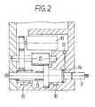
- the motor arm In the horizontal plane perpendicular to the axis 7, the motor arm is penetrated by a motor-driven, axially displaceable clamping bit shaft 5.
- the span bit wave has at both ends a profile 9 that can transmit torques.
- the motor 10 drives the clamping bit shaft 5 via an intermediate shaft 11.
- the motor is preferably equipped with an adjustable maximum torque for clockwise and anti-clockwise rotation.
- the device for the axial movements consists of a compressed air connection 12 and a spring 13. If the compressed air connection 12 is pressurized with compressed air, the chamber 14 is filled with air and the clamping bit shaft 5 is pushed out to the left against the force of the spring 13 from the swivel arm 2. If the compressed air flow ceases, the clamping bit shaft 5 is pushed back into the drawn position by the spring 13. The respectively desired axial position of the clamping bit shaft is determined by the limit switches 15 and 16.
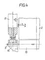
- the swivel arm 2 moves towards the machine tool in such a way that the tool head 18 located in the tool holder 17 can be gripped by the gripper 8.
- the tool head is clamped.
- the clamping bit shaft 5 is engaged axially when the rotation is slow. After the coupling process has been completed, the tool holder tension is released with the relaxation torque.
- the particular advantage of the present invention is that in tool changing devices in which the clamping screw of the automatic clamping unit is in the tool holder, the tool change can be carried out by a swivel arm in which the gripper and clamping unit are integrated. With this device, the tool change can be carried out fully automatically with a unit that operates independently of the machine tool.
- tool positions arranged axially and radially to the machine axis can be achieved by the rotatable mounting of the swivel arm, which allows swivel movement at any angle.
- the clamping bit shaft designed according to the invention which in particular makes it possible to operate both left and right tool holder changing systems, in practice all tool holder systems arranged at different angles in one plane can be operated.
Landscapes
- Engineering & Computer Science (AREA)
- Mechanical Engineering (AREA)
- Automatic Tool Replacement In Machine Tools (AREA)
- Auxiliary Devices For Machine Tools (AREA)
Priority Applications (1)
| Application Number | Priority Date | Filing Date | Title |
|---|---|---|---|
| AT88108249T ATE68388T1 (de) | 1987-06-24 | 1988-05-24 | Automatische werkzeugwechseleinrichtung. |
Applications Claiming Priority (2)
| Application Number | Priority Date | Filing Date | Title |
|---|---|---|---|
| DE19873720805 DE3720805A1 (de) | 1987-06-24 | 1987-06-24 | Automatische werkzeugwechseleinrichtung |
| DE3720805 | 1987-06-24 |
Publications (3)
| Publication Number | Publication Date |
|---|---|
| EP0296367A2 true EP0296367A2 (fr) | 1988-12-28 |
| EP0296367A3 EP0296367A3 (en) | 1989-03-08 |
| EP0296367B1 EP0296367B1 (fr) | 1991-10-16 |
Family
ID=6330168
Family Applications (1)
| Application Number | Title | Priority Date | Filing Date |
|---|---|---|---|
| EP88108249A Expired - Lifetime EP0296367B1 (fr) | 1987-06-24 | 1988-05-24 | Dispositif automatique de changement d'outil |
Country Status (6)
| Country | Link |
|---|---|
| US (1) | US4860429A (fr) |
| EP (1) | EP0296367B1 (fr) |
| JP (1) | JPS6416343A (fr) |
| AT (1) | ATE68388T1 (fr) |
| DE (1) | DE3720805A1 (fr) |
| IN (1) | IN168652B (fr) |
Families Citing this family (23)
| Publication number | Priority date | Publication date | Assignee | Title |
|---|---|---|---|---|
| JPH07108500B2 (ja) * | 1989-09-14 | 1995-11-22 | 第一精機株式会社 | 交換アームの駆動制御装置 |
| US5277686A (en) * | 1991-08-21 | 1994-01-11 | Sandvik Ab | Method and device for changing tools in machine tools |
| IT1255767B (it) * | 1992-05-20 | 1995-11-15 | Dispositivo per il cambio automatico degli utensili in una testa di una foratrice per pannelli | |
| US5896793A (en) * | 1997-04-25 | 1999-04-27 | Ski Industries | Apparatus for feeding bar stock to an automatic screw machine |
| US5911804A (en) | 1997-09-17 | 1999-06-15 | Ski Industries, Inc. | Method and apparatus for feeding shaped bar stock |
| US5954623A (en) * | 1997-10-07 | 1999-09-21 | Davis; Steven E. | Tool changer apparatus and method of automating a machine tool |
| RU2179209C1 (ru) * | 2001-04-16 | 2002-02-10 | Мозырева Елена Анатольевна | Способ делигнификации и отбелки целлюлозных материалов |
| DE10163294B4 (de) * | 2001-12-21 | 2010-09-09 | Deckel Maho Geretsried Gmbh | Werkzeugwechselsystem für programmgesteuerte Fräs- und Bohrmaschinen |
| DE10337547A1 (de) * | 2003-08-05 | 2005-03-03 | Ex-Cell-O Gmbh | Werkzeugwechselvorrichtung für eine Werkzeugmaschine und Verfahren zum Werkzeugwechsel an einer Werkzeugmaschine |
| DE10336869A1 (de) * | 2003-08-11 | 2005-06-09 | Kennametal Inc. | Werkzeugkupplung |
| RU2283909C1 (ru) * | 2004-12-30 | 2006-09-20 | Открытое акционерное общество "Сибирский научно-исследовательский институт лесной, целлюлозно-бумажной промышленности" (ОАО "СибНИИ ЦБП") | Способ отбелки целлюлозы |
| RU2304647C2 (ru) * | 2005-08-24 | 2007-08-20 | Открытое акционерное общество "Научно-исследовательский институт по нефтепромысловой химии" ОАО "НИИнефтепромхим" | Способ получения целлюлозы (варианты) |
| RU2304648C2 (ru) * | 2005-08-24 | 2007-08-20 | Общество с ограниченной ответственностью "Научно-производственное объединение "Нефтепромхим" ООО "НПО "Нефтепромхим" | Способ получения целлюлозы |
| RU2304649C2 (ru) * | 2005-08-24 | 2007-08-20 | Открытое Акционерное Общество "Научно-исследовательский институ по нефтепромысловой химии" ОАО "НИИнефтепромхим" | Способ получения целлюлозы |
| US8277316B2 (en) | 2006-09-14 | 2012-10-02 | Nintendo Co., Ltd. | Method and apparatus for using a common pointing input to control 3D viewpoint and object targeting |
| DE102014105744A1 (de) * | 2014-03-19 | 2015-09-24 | Gebr. Heller Maschinenfabrik Gmbh | Verfahren zum Werkzeugwechsel |
| CN104128831B (zh) * | 2014-07-24 | 2016-09-21 | 肖衍盛 | 超高速电主轴自动换刀装置 |
| CN107813175A (zh) * | 2017-11-30 | 2018-03-20 | 重庆威斯壮智能科技有限公司 | 一种数控中心刀具安装架 |
| KR102065854B1 (ko) * | 2018-08-30 | 2020-03-02 | 현대위아 주식회사 | 공작기계의 자동 공구 교환장치 |
| CN111285124B (zh) * | 2020-02-19 | 2021-09-10 | 新昌县宏满机械科技有限公司 | 一种防滑落的柱体铝合金夹取堆垛装置 |
| CN112427996A (zh) * | 2020-09-27 | 2021-03-02 | 杭州佳菱机械制造有限公司 | 精密零部件智能柔性加工设备 |
| CN112518385B (zh) * | 2020-12-29 | 2022-03-11 | 安徽圣尔沃智能装备有限公司 | 一种智能调节式压铸件切削装置 |
| DE102021108338B4 (de) | 2021-04-01 | 2025-11-13 | Ott-Jakob Spanntechnik Gmbh | Verfahren zur Durchführung eines Werkzeugwechsels und Wechseleinrichtung zur Durchführung des Verfahrens |
Family Cites Families (14)
| Publication number | Priority date | Publication date | Assignee | Title |
|---|---|---|---|---|
| US2374919A (en) * | 1943-09-09 | 1945-05-01 | Edward H Bruseth | Milling and drilling adapter for boring bars |
| US2654407A (en) * | 1952-08-04 | 1953-10-06 | Albert J Dremel | Motor-driven screw driver |
| DD145201B1 (de) * | 1979-07-30 | 1983-06-15 | Ruhla Uhren Veb K | Werkzeughaltevorrichtung an werkzeugmagazinen |
| DE3007440A1 (de) * | 1980-02-28 | 1981-09-17 | Fried. Krupp Gmbh, 4300 Essen | Werkzeugeinrichtung mit wechselbarem werkzeugtraeger |
| SU1085751A1 (ru) * | 1982-10-20 | 1984-04-15 | Ульяновское Головное Специальное Конструкторское Бюро Тяжелых И Фрезерных Станков | Устройство дл креплени оправки в носителе инструмента |
| DE3324312C2 (de) * | 1983-04-20 | 1985-11-28 | Komet Stahlhalter- Und Werkzeugfabrik Robert Breuning Gmbh, 7122 Besigheim | Werkzeugmaschine mit Werkzeugwechselvorrichtung |
| GB8330412D0 (en) * | 1983-11-15 | 1983-12-21 | Renishaw Plc | Tool change apparatus |
| JPS60186343A (ja) * | 1984-03-02 | 1985-09-21 | Enshu Ltd | 自動工具交換装置 |
| DE3410154A1 (de) * | 1984-03-20 | 1985-10-03 | Fried. Krupp Gmbh, 4300 Essen | Werkzeugeinrichtung mit wechselbarem werkzeugkopf |
| JPS61146444A (ja) * | 1984-12-21 | 1986-07-04 | Toshiba Corp | 旋盤 |
| JPS61168442A (ja) * | 1985-01-21 | 1986-07-30 | Toshiba Corp | 旋盤 |
| DE3531160A1 (de) * | 1985-08-31 | 1987-03-12 | Honsberg Gmbh Geb | Werkzeugwechsler fuer eine werkzeugmaschine |
| DE3532667A1 (de) * | 1985-09-13 | 1987-03-26 | Index Werke Kg Hahn & Tessky | Werkzeugwechseleinrichtung fuer einen industrie-roboter |
| DE3602247C2 (de) * | 1986-01-25 | 1997-01-23 | Widia Gmbh | Werkzeugkupplung zur Verbindung eines wechselbaren Werkzeugkopfes mit einem Werkzeughalter an einer Werkzeugmaschine |
-
1987
- 1987-06-24 DE DE19873720805 patent/DE3720805A1/de not_active Withdrawn
-
1988
- 1988-03-30 IN IN268/CAL/88A patent/IN168652B/en unknown
- 1988-05-24 EP EP88108249A patent/EP0296367B1/fr not_active Expired - Lifetime
- 1988-05-24 AT AT88108249T patent/ATE68388T1/de active
- 1988-06-21 JP JP63151351A patent/JPS6416343A/ja active Pending
- 1988-06-23 US US07/210,564 patent/US4860429A/en not_active Expired - Fee Related
Also Published As
| Publication number | Publication date |
|---|---|
| IN168652B (fr) | 1991-05-18 |
| EP0296367B1 (fr) | 1991-10-16 |
| ATE68388T1 (de) | 1991-11-15 |
| US4860429A (en) | 1989-08-29 |
| DE3720805A1 (de) | 1989-01-05 |
| JPS6416343A (en) | 1989-01-19 |
| EP0296367A3 (en) | 1989-03-08 |
Similar Documents
| Publication | Publication Date | Title |
|---|---|---|
| EP0296367A2 (fr) | Dispositif automatique de changement d'outil | |
| DE102018103805B4 (de) | Robotersystem mit rekonfigurierbarer endeffektor-baugruppe | |
| EP3600798B1 (fr) | Système de préhension et de positionnement servant au transport d'un dispositif de serrage entre différentes positions | |
| DE69124438T2 (de) | Positioniervorrichtung | |
| DE3434009C2 (fr) | ||
| DE3731280C2 (fr) | ||
| EP0742081B1 (fr) | Etan universel de précision pour une machine-outil | |
| DE3610317A1 (de) | Automatische zentrier- und greifvorrichtung | |
| EP3870405B1 (fr) | Dispositif pour l'usinage d'une pièce | |
| DE3438478C2 (de) | Zusatzhandgriff für tragbare kraftangetriebene Werkzeuge | |
| DE2830906C2 (de) | Schraubvorrichtung zum Einschrauben und Festziehen von Schrauben mit hohem Anzugsmoment | |
| DE4017351B4 (de) | Automatische Werkzeugmaschine mit einem in den drei kartesischen Achsen bewegbaren Support | |
| DE3519754C2 (fr) | ||
| DE69001771T2 (de) | Anordnung zur Handhabung von Bohrstangen in einem Gesteinsbohraggregat oder dgl. | |
| EP0143257B1 (fr) | Raccordement d'outil d'une presse de découpage, notamment d'une presse de découpage à plateau revolver, pour le changement d'outil | |
| DE3634018C2 (fr) | ||
| EP0255567B1 (fr) | Changeur d'outils pour machine universelle à percer et à fraiser | |
| DE69105028T2 (de) | Steckschlüsselhalter. | |
| DE3226605C2 (fr) | ||
| WO1992003253A1 (fr) | Dispositif de serrage pour machines-outils | |
| DE3818564C2 (fr) | ||
| DE3614807C2 (fr) | ||
| DE2935381C2 (de) | Vorrichtung zum Befestigen von Scharnieren an einer Fahrzeugtüre. | |
| DE10120009A1 (de) | Werkstückhaltevorrichtung und Werkstückhalteverfahren für eine Werkzeugmaschine | |
| DE9318014U1 (de) | Handbetätigbare Werkzeugmaschine |
Legal Events
| Date | Code | Title | Description |
|---|---|---|---|
| PUAI | Public reference made under article 153(3) epc to a published international application that has entered the european phase |
Free format text: ORIGINAL CODE: 0009012 |
|
| AK | Designated contracting states |
Kind code of ref document: A2 Designated state(s): AT CH FR GB LI SE |
|
| PUAL | Search report despatched |
Free format text: ORIGINAL CODE: 0009013 |
|
| AK | Designated contracting states |
Kind code of ref document: A3 Designated state(s): AT CH FR GB LI SE |
|
| 17P | Request for examination filed |
Effective date: 19890506 |
|
| 17Q | First examination report despatched |
Effective date: 19901016 |
|
| GRAA | (expected) grant |
Free format text: ORIGINAL CODE: 0009210 |
|
| AK | Designated contracting states |
Kind code of ref document: B1 Designated state(s): AT CH FR GB LI SE |
|
| REF | Corresponds to: |
Ref document number: 68388 Country of ref document: AT Date of ref document: 19911115 Kind code of ref document: T |
|
| GBT | Gb: translation of ep patent filed (gb section 77(6)(a)/1977) | ||
| ET | Fr: translation filed | ||
| PLBE | No opposition filed within time limit |
Free format text: ORIGINAL CODE: 0009261 |
|
| STAA | Information on the status of an ep patent application or granted ep patent |
Free format text: STATUS: NO OPPOSITION FILED WITHIN TIME LIMIT |
|
| 26N | No opposition filed | ||
| PGFP | Annual fee paid to national office [announced via postgrant information from national office to epo] |
Ref country code: GB Payment date: 19930423 Year of fee payment: 6 |
|
| PGFP | Annual fee paid to national office [announced via postgrant information from national office to epo] |
Ref country code: FR Payment date: 19930518 Year of fee payment: 6 |
|
| PGFP | Annual fee paid to national office [announced via postgrant information from national office to epo] |
Ref country code: SE Payment date: 19930526 Year of fee payment: 6 |
|
| PGFP | Annual fee paid to national office [announced via postgrant information from national office to epo] |
Ref country code: AT Payment date: 19930527 Year of fee payment: 6 |
|
| PGFP | Annual fee paid to national office [announced via postgrant information from national office to epo] |
Ref country code: CH Payment date: 19930713 Year of fee payment: 6 |
|
| PG25 | Lapsed in a contracting state [announced via postgrant information from national office to epo] |
Ref country code: GB Effective date: 19940524 Ref country code: AT Effective date: 19940524 |
|
| PG25 | Lapsed in a contracting state [announced via postgrant information from national office to epo] |
Ref country code: SE Effective date: 19940525 |
|
| PG25 | Lapsed in a contracting state [announced via postgrant information from national office to epo] |
Ref country code: LI Effective date: 19940531 Ref country code: CH Effective date: 19940531 |
|
| GBPC | Gb: european patent ceased through non-payment of renewal fee |
Effective date: 19940524 |
|
| EUG | Se: european patent has lapsed |
Ref document number: 88108249.9 Effective date: 19941210 |
|
| PG25 | Lapsed in a contracting state [announced via postgrant information from national office to epo] |
Ref country code: FR Effective date: 19950131 |
|
| REG | Reference to a national code |
Ref country code: CH Ref legal event code: PL |
|
| EUG | Se: european patent has lapsed |
Ref document number: 88108249.9 |
|
| REG | Reference to a national code |
Ref country code: FR Ref legal event code: ST |