EP0297493A2 - Dispositif de protection des extremités de tuyaux - Google Patents
Dispositif de protection des extremités de tuyaux Download PDFInfo
- Publication number
- EP0297493A2 EP0297493A2 EP88110251A EP88110251A EP0297493A2 EP 0297493 A2 EP0297493 A2 EP 0297493A2 EP 88110251 A EP88110251 A EP 88110251A EP 88110251 A EP88110251 A EP 88110251A EP 0297493 A2 EP0297493 A2 EP 0297493A2
- Authority
- EP
- European Patent Office
- Prior art keywords
- insert
- protection device
- cover
- circumferential
- metal
- Prior art date
- Legal status (The legal status is an assumption and is not a legal conclusion. Google has not performed a legal analysis and makes no representation as to the accuracy of the status listed.)
- Granted
Links
Images



Classifications
-
- B—PERFORMING OPERATIONS; TRANSPORTING
- B65—CONVEYING; PACKING; STORING; HANDLING THIN OR FILAMENTARY MATERIAL
- B65D—CONTAINERS FOR STORAGE OR TRANSPORT OF ARTICLES OR MATERIALS, e.g. BAGS, BARRELS, BOTTLES, BOXES, CANS, CARTONS, CRATES, DRUMS, JARS, TANKS, HOPPERS, FORWARDING CONTAINERS; ACCESSORIES, CLOSURES, OR FITTINGS THEREFOR; PACKAGING ELEMENTS; PACKAGES
- B65D59/00—Plugs, sleeves, caps, or like rigid or semi-rigid elements for protecting parts of articles or for bundling articles, e.g. protectors for screw-threads, end caps for tubes or for bundling rod-shaped articles
- B65D59/06—Caps
-
- F—MECHANICAL ENGINEERING; LIGHTING; HEATING; WEAPONS; BLASTING
- F16—ENGINEERING ELEMENTS AND UNITS; GENERAL MEASURES FOR PRODUCING AND MAINTAINING EFFECTIVE FUNCTIONING OF MACHINES OR INSTALLATIONS; THERMAL INSULATION IN GENERAL
- F16L—PIPES; JOINTS OR FITTINGS FOR PIPES; SUPPORTS FOR PIPES, CABLES OR PROTECTIVE TUBING; MEANS FOR THERMAL INSULATION IN GENERAL
- F16L57/00—Protection of pipes or objects of similar shape against external or internal damage or wear
- F16L57/005—Protection of pipes or objects of similar shape against external or internal damage or wear specially adapted for the ends of pipes
Definitions
- the invention relates to a protective device for pipe ends according to the preamble of claim 1.
- Protective devices with one-piece inserts or covers as well as protective devices which consist only of plastic also have the disadvantage that they are difficult to dismantle at low temperatures due to the contraction of the plastic and are even more difficult to assemble. This can occur when using such protective devices, e.g. B. on oil pipes, which are used at very different temperatures, lead to considerable problems, in particular when used on large diameter pipes.
- the object of the present invention is therefore to design a protective device of the type mentioned at the outset in such a way that greater stability can be achieved. Furthermore, the production should be facilitated.
- Protective devices of the type specified in claim 1 and dependent claim 2 have a considerably higher stability than the previously known protective devices, namely by the flanged or folded or rolled edge.
- the metal housing designed according to the invention and the metal plug designed according to the invention are the same advantageous, can be used for both one-piece and multi-piece inserts and covers.
- the grooves designed in use can be used, for example, for inserting a base in order to make a closed protective cap from an open protective cap.
- Separate sealing elements can also be inserted into the grooves, as can be gathered from claim 9.
- molded thin-walled webs can also be provided as axial sealing rings.
- the development according to claim 10 enables the insertion of a rod-shaped auxiliary tool for assembling and disassembling the protective devices.
- the bent tongues serve to reinforce the attachment surfaces of the auxiliary tool and at the same time act as drivers for the plastic insert, since they lie against the lateral boundaries of the insert or the cover.
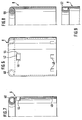
- FIGS. 1 to 5 and 10 an insert 2 consisting of two halves 4, 6 for a metal housing 8 according to FIGS. 6 to 9 and 11.
- Each half of the insert is semi-cylindrical and has a thickened end on the end face 10 on.
- a thread 12 is formed on the inner surface.
- a circumferential circumferential groove 14 can be formed on the outer surface.
- Each insert half has two contact surfaces 16, 18 and 16 ', 18', of which only one can be seen in FIGS. 1 to 5, which is provided with the reference numerals 16 and 16 '.
- the contact surfaces of one insert half 4 have a groove 20 and the contact surfaces of the other insert half have a tongue 22 complementary to the groove.
- One contact surface of the insert halves 4 and 6 can also be provided with a groove and the other contact surface with a corresponding tongue.
- the tongue and the groove have a radially inward bend or bend 24.
- the insert halves 4 and 6 according to FIGS. 1 and 2 also have a groove 26 on the inside in the region of the thickened end 10.
- the groove 26 forms a circumferential inner annular groove into which, for example, a plastic cover 28 can be inserted, in order to form a closed protective cap, as is shown in FIG. 3.
- the lid can also have a pot shape 30, as shown in FIG. 4.
- FIG. 5 shows an embodiment in which a lip seal 30 is inserted into the groove 26 and has a lip 36 which projects beyond the sealing gap 32 between a tube 34 and the insert 2.
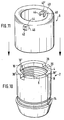
- the thickened end of the end face of the insert halves is each provided with a rectangular recess 38, 38 '. This can be seen particularly clearly in FIG. 10, which shows the two insert halves 4 and 6 in the assembled state.
- FIGS. 6 to 9 and 11, show different embodiments of the metal housing 8.
- 6 shows a metal housing, the outer end edge of which is provided with an inwardly directed rolling edge 40.
- the cylindrical metal housing 8 has two diametrically opposite openings 42, 42 'with two lateral inwardly bent tongues 44, 46, as can be seen particularly clearly in FIGS. 7 and 11.
- the tongues 44 and 46 engage in the recesses 38, 38 ', whereby a locking is achieved in the circumferential direction.
- a rod-shaped tool can be inserted through the openings 42, 42 'and the recesses 38, 38' during assembly and disassembly of the protective device.
- the metal housing has inwardly distributed tongues 48 which engage in the circumferential groove 14 of the insert 2 and thereby bring about an axial fixation.
- the rolled edge is formed in a spiral shape 50, wherein the spiral can also be formed so far that the spiral cavity is completely filled.
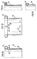
- a hollow cylindrical metal plug 54 is shown, which has an outwardly directed rolling edge 56 at its outer front end.
- the metal plug 50 is surrounded by coating halves, which are not shown, but are designed quite analogously to the insert halves 4 and 6 according to FIGS. 1 to 5.
- the metal plug 54 has two diametrically opposite openings 58 with lateral outwardly directed tongues 60, 62 , see. also Fig. 13. These tongues 60, 62 engage in corresponding recesses of the coating, not shown, in a manner analogous to that of the metal housing 8.
- FIG. 14 and 15 show two further embodiments of the metal stopper, the rolled edge being designed in the form of a spiral 64 in the embodiment according to FIG. 14 and in the form of an oval 66 in the embodiment according to FIG. 15.
- the insert 2 can have a circumferential groove for an O-ring 72 on the inside at this end, which in the Fig. 4 is shown in dashed lines for the insert half 6, or have a circumferential, molded, tapered sealing web 74 on the inside at this end 68, which is shown in dashed lines in FIG. 3 for the one insert half 6.
- cover of a protective plug can have a groove on the outside for an O-ring or a molded, circumferential sealing web, which is not shown in the drawing.
- FIG. 16 shows, in section, a protective cap 80 which has a hollow cylindrical metal housing 82 with a sleeve-shaped insert 84 made of elastomeric material which lies tightly against the metal housing.
- the metal cylinder 82 has an inwardly bent flanged edge 86 at the outer end.
- the insert 84 protrudes into the flanging of the flanged edge 86 in such a way that the inwardly bent part of the flanged edge overlaps the end of the insert and the free flanged edge 88 engages in the insert or is clamped against the insert.
- the insert 84 has a circumferential stop 90 for the tube end 92, an intermediate space 94 being left in the manner of a groove between the stop 90 and the flanged edge 86 of the metal housing 82, into which an elastic cover 96 can be snapped out again.
- the stop 90 like the embodiment according to FIG. 5, has a circumferential seal 30 to cover the sealing gap 32 between the stop and the pipe end 92.
- FIG. 17 shows in section a protective plug 100 which has a hollow cylindrical metal plug 102 with a sleeve-shaped coating 104 made of elastomeric material.
- the hollow cylindrical metal plug has a flanged edge 106 which is bent outwards at the end.
- the cover 104 protrudes into the flanging of the flanged edge 106 in such a way that the outwardly bent part of the flanged edge overlaps the end of the cover 104 and the free flanged edge 107 engages in the cover or is clamped against the cover.
- the cover 104 has a circumferential stop 108 for the pipe end 100.
- the metal stopper has a circumferential recess or a plurality of spaced recesses 112 on the inside in the region of the flanged edge 106, into which an elastic cover 114 with a circumferential rib or with a plurality of spaced projections 116 can be snapped out again.
- a circumferential seal 118 On the ring-shaped pipe stop surface of the An Impact 108 is formed to cover the gap between the stop and the pipe end, a circumferential seal 118 in the form of a sealing lip, which in the unloaded state shows obliquely outwards (shown in dashed lines). However, there can also be a groove 120 (shown in broken lines) for an insertable seal.
Landscapes
- Engineering & Computer Science (AREA)
- Mechanical Engineering (AREA)
- General Engineering & Computer Science (AREA)
- Protection Of Pipes Against Damage, Friction, And Corrosion (AREA)
- Cable Accessories (AREA)
- Laying Of Electric Cables Or Lines Outside (AREA)
- Gasket Seals (AREA)
- Orthopedics, Nursing, And Contraception (AREA)
- Quick-Acting Or Multi-Walled Pipe Joints (AREA)
- Buffer Packaging (AREA)
Priority Applications (2)
| Application Number | Priority Date | Filing Date | Title |
|---|---|---|---|
| AT88110251T ATE91765T1 (de) | 1987-06-30 | 1988-06-28 | Schutzvorrichtung fuer rohrenden. |
| EP92115143A EP0519524B1 (fr) | 1987-06-30 | 1988-06-28 | Dispositif de protection des extrémités de tuyaux |
Applications Claiming Priority (2)
| Application Number | Priority Date | Filing Date | Title |
|---|---|---|---|
| DE3721541 | 1987-06-30 | ||
| DE19873721541 DE3721541A1 (de) | 1987-06-30 | 1987-06-30 | Schutzvorrichtung fuer rohrenden |
Related Child Applications (1)
| Application Number | Title | Priority Date | Filing Date |
|---|---|---|---|
| EP92115143.7 Division-Into | 1992-09-04 |
Publications (3)
| Publication Number | Publication Date |
|---|---|
| EP0297493A2 true EP0297493A2 (fr) | 1989-01-04 |
| EP0297493A3 EP0297493A3 (en) | 1989-10-18 |
| EP0297493B1 EP0297493B1 (fr) | 1993-07-21 |
Family
ID=6330578
Family Applications (2)
| Application Number | Title | Priority Date | Filing Date |
|---|---|---|---|
| EP92115143A Expired - Lifetime EP0519524B1 (fr) | 1987-06-30 | 1988-06-28 | Dispositif de protection des extrémités de tuyaux |
| EP88110251A Expired - Lifetime EP0297493B1 (fr) | 1987-06-30 | 1988-06-28 | Dispositif de protection des extremités de tuyaux |
Family Applications Before (1)
| Application Number | Title | Priority Date | Filing Date |
|---|---|---|---|
| EP92115143A Expired - Lifetime EP0519524B1 (fr) | 1987-06-30 | 1988-06-28 | Dispositif de protection des extrémités de tuyaux |
Country Status (9)
| Country | Link |
|---|---|
| EP (2) | EP0519524B1 (fr) |
| JP (1) | JP2610652B2 (fr) |
| CN (1) | CN1015403B (fr) |
| AT (2) | ATE91765T1 (fr) |
| BR (1) | BR8803252A (fr) |
| CA (1) | CA1291954C (fr) |
| DE (3) | DE3721541A1 (fr) |
| ES (2) | ES2082307T3 (fr) |
| SU (1) | SU1669406A3 (fr) |
Cited By (7)
| Publication number | Priority date | Publication date | Assignee | Title |
|---|---|---|---|---|
| EP0639869A3 (fr) * | 1993-08-17 | 1996-07-17 | Whitaker Corp | Borne ou ramificateur serti, étanche, et anticorrosif. |
| US5749756A (en) * | 1995-10-27 | 1998-05-12 | The Whitaker Corporation | Sealed corrosion-proof crimped terminal of splice |
| DE102005054815A1 (de) * | 2005-11-15 | 2007-05-16 | Thread Guard Technology Ltd | Zweiteiliger Protektor für ein mit einem Außen- oder Innengewinde versehenes Rohrende |
| EP1788298A1 (fr) * | 2005-11-22 | 2007-05-23 | Siderca S.A.I.C. | Ensemble de protection pour l'extrémité filetée d'une conduite et son intérieur comprenant un élément de protection fileté ouvert et un couvercle pouvant être intégré dans celui-ci |
| EP2278398A2 (fr) | 2002-05-31 | 2011-01-26 | Fujifilm Corporation | Composition pour réserve de type positif |
| EP2979805A3 (fr) * | 2014-07-30 | 2016-06-15 | Airbus DS GmbH | Dispositif de protection pour un corps creux longitudinal avec deux demi coques et un chapeau |
| EP4091786A1 (fr) * | 2021-05-18 | 2022-11-23 | Voss Automotive GmbH | Liaison vissée |
Families Citing this family (13)
| Publication number | Priority date | Publication date | Assignee | Title |
|---|---|---|---|---|
| CH692429A5 (de) * | 1997-05-22 | 2002-06-14 | Nueva Ag | Rohrverbindung. |
| RU2285193C1 (ru) * | 2005-09-13 | 2006-10-10 | Харис Касьянович Мухаметдинов | Транспортная заглушка для труб мухаметдинова |
| RU2474751C2 (ru) * | 2007-08-21 | 2013-02-10 | Сидерка С.А.И.С. | Защитное устройство для окончания трубы |
| MD3982G2 (ro) * | 2008-05-22 | 2010-06-30 | Николай БАРБУЛ | Subansamblu de intrare şi ieşire a conductei polimere de gaze şi procedeu de confecţionare a acestuia |
| DE102009017975A1 (de) * | 2008-12-23 | 2010-07-08 | Rosen Swiss Ag | Sicherheitsvorrichtung und System zur Überwachung von Rohren |
| NL2003992C2 (en) * | 2009-12-21 | 2011-06-22 | Pipe Proteq B V | Wellbore pipe protection device. |
| CN103482215B (zh) * | 2013-09-23 | 2015-11-11 | 河北新兴铸管有限公司 | 用于保护球墨铸铁管管口的外翻式保护套 |
| CN105366192A (zh) * | 2014-08-24 | 2016-03-02 | 天津市津英达塑料制品有限责任公司 | 一种内螺纹保护器的止回装置 |
| CN105438630A (zh) * | 2014-08-24 | 2016-03-30 | 天津市津英达塑料制品有限责任公司 | 一种外螺纹保护器的止回装置 |
| CN104613276A (zh) * | 2015-01-28 | 2015-05-13 | 苏州洛特兰新材料科技有限公司 | 氧化锆陶瓷开口套管 |
| CN106402571A (zh) * | 2016-10-20 | 2017-02-15 | 陈红玲 | 密封锁紧支撑套 |
| RU178318U1 (ru) * | 2017-06-01 | 2018-03-29 | Акционерное общество "Выксунский металлургический завод" (АО "ВМЗ") | Заглушка защитная для труб |
| RU184845U1 (ru) * | 2018-05-15 | 2018-11-12 | Публичное акционерное общество "Трубная металлургическая компания" (ПАО "ТМК") | Предохранитель резьбы ниппельного элемента резьбовых соединений нефтегазопромысловых труб |
Family Cites Families (13)
| Publication number | Priority date | Publication date | Assignee | Title |
|---|---|---|---|---|
| DE163744C (fr) * | ||||
| US2543960A (en) * | 1947-02-20 | 1951-03-06 | Pittsburgh Screw And Bolt Corp | Thread protector |
| US3000402A (en) * | 1958-02-12 | 1961-09-19 | Phillips Petroleum Co | Thread protector |
| US4020873A (en) * | 1975-07-18 | 1977-05-03 | Precise Metals & Plastics, Inc. | Thread protector for an externally threaded pipe |
| DE2939383A1 (de) * | 1979-09-28 | 1981-04-02 | Dreyfuß GmbH, 3111 Eimke | Vorrichtung zum schutz von hohlraeumen |
| FR2499030A2 (fr) * | 1981-01-30 | 1982-08-06 | Flimon Jacques | Dispositif protecteur pour tubes de forage, notamment petroliers |
| JPS58174472U (ja) * | 1982-05-18 | 1983-11-21 | 日豊工機株式会社 | 管端ネジ保護具 |
| DE3226794A1 (de) * | 1982-07-17 | 1984-01-19 | Gummi-Jäger KG GmbH & Cie, 3000 Hannover | Vorrichtung zum schutz des gewindes an rohrenden |
| GB8303753D0 (en) * | 1983-02-10 | 1983-03-16 | Ae Plc | Piston and assemblies |
| EP0153315A1 (fr) * | 1983-04-26 | 1985-09-04 | Hydril Company | Protecteur de filetage d'un organe tubulaire |
| JPS6071793U (ja) * | 1983-10-21 | 1985-05-21 | 日鐵建材工業株式会社 | 管端ねじ保護具 |
| JPS6076660U (ja) * | 1983-10-31 | 1985-05-29 | 日鐵建材工業株式会社 | 管のねじ保護具 |
| US4655256A (en) * | 1985-01-14 | 1987-04-07 | Ampco-Pittsburgh Corporation | Threaded end protector and component |
-
1987
- 1987-06-30 DE DE19873721541 patent/DE3721541A1/de active Granted
-
1988
- 1988-06-28 ES ES92115143T patent/ES2082307T3/es not_active Expired - Lifetime
- 1988-06-28 EP EP92115143A patent/EP0519524B1/fr not_active Expired - Lifetime
- 1988-06-28 EP EP88110251A patent/EP0297493B1/fr not_active Expired - Lifetime
- 1988-06-28 AT AT88110251T patent/ATE91765T1/de not_active IP Right Cessation
- 1988-06-28 AT AT92115143T patent/ATE130416T1/de not_active IP Right Cessation
- 1988-06-28 ES ES198888110251T patent/ES2046240T3/es not_active Expired - Lifetime
- 1988-06-28 DE DE8888110251T patent/DE3882451D1/de not_active Expired - Fee Related
- 1988-06-28 DE DE3854698T patent/DE3854698D1/de not_active Expired - Fee Related
- 1988-06-29 JP JP63159585A patent/JP2610652B2/ja not_active Expired - Lifetime
- 1988-06-30 SU SU884356102A patent/SU1669406A3/ru active
- 1988-06-30 BR BR8803252A patent/BR8803252A/pt not_active IP Right Cessation
- 1988-06-30 CN CN88104307A patent/CN1015403B/zh not_active Expired
- 1988-06-30 CA CA000570882A patent/CA1291954C/fr not_active Expired - Lifetime
Cited By (11)
| Publication number | Priority date | Publication date | Assignee | Title |
|---|---|---|---|---|
| EP0639869A3 (fr) * | 1993-08-17 | 1996-07-17 | Whitaker Corp | Borne ou ramificateur serti, étanche, et anticorrosif. |
| US5749756A (en) * | 1995-10-27 | 1998-05-12 | The Whitaker Corporation | Sealed corrosion-proof crimped terminal of splice |
| EP2278398A2 (fr) | 2002-05-31 | 2011-01-26 | Fujifilm Corporation | Composition pour réserve de type positif |
| DE102005054815A1 (de) * | 2005-11-15 | 2007-05-16 | Thread Guard Technology Ltd | Zweiteiliger Protektor für ein mit einem Außen- oder Innengewinde versehenes Rohrende |
| WO2007057047A1 (fr) * | 2005-11-15 | 2007-05-24 | Thread Guard Technology Ltd. | Protecteur en deux pieces pour extremite de tube dotee d'un filet exterieur ou d'un filet interieur |
| EA013581B1 (ru) * | 2005-11-15 | 2010-06-30 | Тред Гард Текнолоджи Лтд. | Сборный предохранитель для конца трубы, снабженного наружной или внутренней резьбой |
| US7857007B2 (en) | 2005-11-15 | 2010-12-28 | Thread Guard Technology Ltd. | Two-part protector for a pipe end which is provided with an external or internal thread |
| AU2005338298B2 (en) * | 2005-11-15 | 2011-02-03 | Thread Guard Technology Ltd. | Two-part protector for a pipe end which is provided with an external or internal thread |
| EP1788298A1 (fr) * | 2005-11-22 | 2007-05-23 | Siderca S.A.I.C. | Ensemble de protection pour l'extrémité filetée d'une conduite et son intérieur comprenant un élément de protection fileté ouvert et un couvercle pouvant être intégré dans celui-ci |
| EP2979805A3 (fr) * | 2014-07-30 | 2016-06-15 | Airbus DS GmbH | Dispositif de protection pour un corps creux longitudinal avec deux demi coques et un chapeau |
| EP4091786A1 (fr) * | 2021-05-18 | 2022-11-23 | Voss Automotive GmbH | Liaison vissée |
Also Published As
| Publication number | Publication date |
|---|---|
| ES2046240T3 (es) | 1994-02-01 |
| ATE130416T1 (de) | 1995-12-15 |
| BR8803252A (pt) | 1989-01-31 |
| EP0519524A3 (en) | 1993-06-09 |
| CN1030822A (zh) | 1989-02-01 |
| DE3882451D1 (de) | 1993-08-26 |
| ATE91765T1 (de) | 1993-08-15 |
| CN1015403B (zh) | 1992-02-05 |
| EP0519524B1 (fr) | 1995-11-15 |
| CA1291954C (fr) | 1991-11-12 |
| ES2082307T3 (es) | 1996-03-16 |
| JP2610652B2 (ja) | 1997-05-14 |
| DE3721541C2 (fr) | 1993-04-22 |
| SU1669406A3 (ru) | 1991-08-07 |
| JPS6479498A (en) | 1989-03-24 |
| DE3721541A1 (de) | 1989-01-12 |
| DE3854698D1 (de) | 1995-12-21 |
| EP0519524A2 (fr) | 1992-12-23 |
| EP0297493B1 (fr) | 1993-07-21 |
| EP0297493A3 (en) | 1989-10-18 |
Similar Documents
| Publication | Publication Date | Title |
|---|---|---|
| EP0297493A2 (fr) | Dispositif de protection des extremités de tuyaux | |
| DE102007047860B3 (de) | Verbindungselement mit einer Schraube und einer daran unverlierbar angeordneten Hülse | |
| DE2304676A1 (de) | Werkstueck, insbesondere dichtungselement, aus elastischem material mit elastischer verstaerkung | |
| DE29521903U1 (de) | Montageeinheit aus einem Montageteil, einem Fixierteil und einer Hülse als Verliersicherung | |
| DE102009048160A1 (de) | Einformbarer Drahtgewindeeinsatz, Verfahren zu seiner Herstellung, Bauteil mit einformbarem Drahtgewindeeinsatz sowie ein Verfahren zu seiner Herstellung | |
| EP0779443B1 (fr) | Corps de palier avec capuchon protecteur | |
| DE4034953C2 (de) | Rohrverbund aus Betonverbundrohren mit einem als Ummantelung dienenden Betonrohr und einem als Innenauskleidung des Betonrohres dienenden Kunststoffrohr | |
| EP1559943A1 (fr) | Dispositif de raccord pour tuyaux pour fluide | |
| EP0132673B1 (fr) | Dispositif de raccordement pour conduits sous pression | |
| DE3826474A1 (de) | Kabeldurchfuehrung mit zugentlastung | |
| DE10334898B4 (de) | Halteelement zur Fixierung wenigstens eines Lagers | |
| DE2602002A1 (de) | Sicherungs- und/oder distanzring | |
| DE68907211T2 (de) | Markierungsanordnung. | |
| EP0303127B1 (fr) | Dispositif avec un élément de vis et élément d'écrou et utilisation du dispositif | |
| DE102007014508A1 (de) | Spuleneinrichtung für Draht, insbesondere für Schweißdraht | |
| EP0631081A1 (fr) | Dispositif de connexion pour conduites avec collier de serrage fendu | |
| EP4158233B1 (fr) | Fiche de connexion et ensemble fiche formé à partir de celle-ci | |
| EP0718538A1 (fr) | Raccord enfichables | |
| DE3309936A1 (de) | Nippel zum drehbaren anschluss eines schlauches | |
| DE3109583A1 (de) | Kabelverschraubung | |
| DE102016216087B4 (de) | Aktuator, insbesondere einer Hinterachslenkung | |
| DE102010052745B4 (de) | Thermostatventilunterteil | |
| DE2538440A1 (de) | Loesbare verschlusseinrichtung zum abdichten von hohlkoerpern, insbesondere von heizkoerpern | |
| DE1588529C (de) | Schraubkappe für Sicherungselemente | |
| DE8104809U1 (de) | Aus Kunststoff bestehendes einstückiges Lagergehäuse |
Legal Events
| Date | Code | Title | Description |
|---|---|---|---|
| PUAI | Public reference made under article 153(3) epc to a published international application that has entered the european phase |
Free format text: ORIGINAL CODE: 0009012 |
|
| AK | Designated contracting states |
Kind code of ref document: A2 Designated state(s): AT BE CH DE ES FR GB GR IT LI LU NL SE |
|
| PUAL | Search report despatched |
Free format text: ORIGINAL CODE: 0009013 |
|
| AK | Designated contracting states |
Kind code of ref document: A3 Designated state(s): AT BE CH DE ES FR GB GR IT LI LU NL SE |
|
| 17P | Request for examination filed |
Effective date: 19900317 |
|
| RAP1 | Party data changed (applicant data changed or rights of an application transferred) |
Owner name: DRILLTEC PATENTS & TECHNOLOGIES COMPANY, INC. |
|
| 17Q | First examination report despatched |
Effective date: 19901210 |
|
| ITCL | It: translation for ep claims filed |
Representative=s name: MODIANO & ASSOCIATI S.R.L. |
|
| GRAA | (expected) grant |
Free format text: ORIGINAL CODE: 0009210 |
|
| AK | Designated contracting states |
Kind code of ref document: B1 Designated state(s): AT BE CH DE ES FR GB GR IT LI LU NL SE |
|
| PG25 | Lapsed in a contracting state [announced via postgrant information from national office to epo] |
Ref country code: GR Free format text: LAPSE BECAUSE OF FAILURE TO SUBMIT A TRANSLATION OF THE DESCRIPTION OR TO PAY THE FEE WITHIN THE PRESCRIBED TIME-LIMIT Effective date: 19930721 |
|
| REF | Corresponds to: |
Ref document number: 91765 Country of ref document: AT Date of ref document: 19930815 Kind code of ref document: T |
|
| ITF | It: translation for a ep patent filed | ||
| ET | Fr: translation filed | ||
| GBT | Gb: translation of ep patent filed (gb section 77(6)(a)/1977) |
Effective date: 19930726 |
|
| REF | Corresponds to: |
Ref document number: 3882451 Country of ref document: DE Date of ref document: 19930826 |
|
| REG | Reference to a national code |
Ref country code: ES Ref legal event code: FG2A Ref document number: 2046240 Country of ref document: ES Kind code of ref document: T3 |
|
| PLBE | No opposition filed within time limit |
Free format text: ORIGINAL CODE: 0009261 |
|
| STAA | Information on the status of an ep patent application or granted ep patent |
Free format text: STATUS: NO OPPOSITION FILED WITHIN TIME LIMIT |
|
| PGFP | Annual fee paid to national office [announced via postgrant information from national office to epo] |
Ref country code: LU Payment date: 19940531 Year of fee payment: 7 |
|
| PGFP | Annual fee paid to national office [announced via postgrant information from national office to epo] |
Ref country code: CH Payment date: 19940627 Year of fee payment: 7 |
|
| 26N | No opposition filed | ||
| EPTA | Lu: last paid annual fee | ||
| EAL | Se: european patent in force in sweden |
Ref document number: 88110251.1 |
|
| PGFP | Annual fee paid to national office [announced via postgrant information from national office to epo] |
Ref country code: SE Payment date: 19950627 Year of fee payment: 8 |
|
| PG25 | Lapsed in a contracting state [announced via postgrant information from national office to epo] |
Ref country code: LU Free format text: LAPSE BECAUSE OF NON-PAYMENT OF DUE FEES Effective date: 19950628 |
|
| PGFP | Annual fee paid to national office [announced via postgrant information from national office to epo] |
Ref country code: NL Payment date: 19950629 Year of fee payment: 8 |
|
| PG25 | Lapsed in a contracting state [announced via postgrant information from national office to epo] |
Ref country code: LI Effective date: 19950630 Ref country code: CH Effective date: 19950630 |
|
| REG | Reference to a national code |
Ref country code: CH Ref legal event code: PL |
|
| PG25 | Lapsed in a contracting state [announced via postgrant information from national office to epo] |
Ref country code: SE Effective date: 19960629 |
|
| PG25 | Lapsed in a contracting state [announced via postgrant information from national office to epo] |
Ref country code: NL Effective date: 19970101 |
|
| EUG | Se: european patent has lapsed |
Ref document number: 88110251.1 |
|
| NLV4 | Nl: lapsed or anulled due to non-payment of the annual fee |
Effective date: 19970101 |
|
| REG | Reference to a national code |
Ref country code: GB Ref legal event code: 732E |
|
| REG | Reference to a national code |
Ref country code: GB Ref legal event code: 732E |
|
| REG | Reference to a national code |
Ref country code: GB Ref legal event code: IF02 |
|
| PGFP | Annual fee paid to national office [announced via postgrant information from national office to epo] |
Ref country code: AT Payment date: 20040603 Year of fee payment: 17 |
|
| PGFP | Annual fee paid to national office [announced via postgrant information from national office to epo] |
Ref country code: GB Payment date: 20040623 Year of fee payment: 17 |
|
| PGFP | Annual fee paid to national office [announced via postgrant information from national office to epo] |
Ref country code: ES Payment date: 20040708 Year of fee payment: 17 |
|
| PGFP | Annual fee paid to national office [announced via postgrant information from national office to epo] |
Ref country code: BE Payment date: 20040715 Year of fee payment: 17 |
|
| PGFP | Annual fee paid to national office [announced via postgrant information from national office to epo] |
Ref country code: DE Payment date: 20040802 Year of fee payment: 17 |
|
| PG25 | Lapsed in a contracting state [announced via postgrant information from national office to epo] |
Ref country code: GB Free format text: LAPSE BECAUSE OF NON-PAYMENT OF DUE FEES Effective date: 20050628 Ref country code: AT Free format text: LAPSE BECAUSE OF NON-PAYMENT OF DUE FEES Effective date: 20050628 |
|
| PG25 | Lapsed in a contracting state [announced via postgrant information from national office to epo] |
Ref country code: ES Free format text: LAPSE BECAUSE OF NON-PAYMENT OF DUE FEES Effective date: 20050629 |
|
| PG25 | Lapsed in a contracting state [announced via postgrant information from national office to epo] |
Ref country code: BE Free format text: LAPSE BECAUSE OF NON-PAYMENT OF DUE FEES Effective date: 20050630 |
|
| PG25 | Lapsed in a contracting state [announced via postgrant information from national office to epo] |
Ref country code: DE Free format text: LAPSE BECAUSE OF NON-PAYMENT OF DUE FEES Effective date: 20060103 |
|
| GBPC | Gb: european patent ceased through non-payment of renewal fee |
Effective date: 20050628 |
|
| REG | Reference to a national code |
Ref country code: ES Ref legal event code: FD2A Effective date: 20050629 |
|
| BERE | Be: lapsed |
Owner name: DRILLTEC *PATENTS & *TECHNOLOGIES CY INC. Effective date: 20050630 |
|
| PGFP | Annual fee paid to national office [announced via postgrant information from national office to epo] |
Ref country code: IT Payment date: 20070628 Year of fee payment: 20 |
|
| PGFP | Annual fee paid to national office [announced via postgrant information from national office to epo] |
Ref country code: FR Payment date: 20070618 Year of fee payment: 20 |