EP0297662A2 - Datenübertragungssystem - Google Patents
Datenübertragungssystem Download PDFInfo
- Publication number
- EP0297662A2 EP0297662A2 EP88201294A EP88201294A EP0297662A2 EP 0297662 A2 EP0297662 A2 EP 0297662A2 EP 88201294 A EP88201294 A EP 88201294A EP 88201294 A EP88201294 A EP 88201294A EP 0297662 A2 EP0297662 A2 EP 0297662A2
- Authority
- EP
- European Patent Office
- Prior art keywords
- electrically conductive
- measuring device
- measuring
- freely movable
- electrically
- Prior art date
- Legal status (The legal status is an assumption and is not a legal conclusion. Google has not performed a legal analysis and makes no representation as to the accuracy of the status listed.)
- Granted
Links
Images
Classifications
-
- G—PHYSICS
- G01—MEASURING; TESTING
- G01F—MEASURING VOLUME, VOLUME FLOW, MASS FLOW OR LIQUID LEVEL; METERING BY VOLUME
- G01F23/00—Indicating or measuring liquid level or level of fluent solid material, e.g. indicating in terms of volume or indicating by means of an alarm
- G01F23/30—Indicating or measuring liquid level or level of fluent solid material, e.g. indicating in terms of volume or indicating by means of an alarm by floats
- G01F23/56—Indicating or measuring liquid level or level of fluent solid material, e.g. indicating in terms of volume or indicating by means of an alarm by floats using elements rigidly fixed to, and rectilinearly moving with, the floats as transmission elements
- G01F23/60—Indicating or measuring liquid level or level of fluent solid material, e.g. indicating in terms of volume or indicating by means of an alarm by floats using elements rigidly fixed to, and rectilinearly moving with, the floats as transmission elements using electrically actuated indicating means
-
- G—PHYSICS
- G01—MEASURING; TESTING
- G01D—MEASURING NOT SPECIALLY ADAPTED FOR A SPECIFIC VARIABLE; ARRANGEMENTS FOR MEASURING TWO OR MORE VARIABLES NOT COVERED IN A SINGLE OTHER SUBCLASS; TARIFF METERING APPARATUS; MEASURING OR TESTING NOT OTHERWISE PROVIDED FOR
- G01D5/00—Mechanical means for transferring the output of a sensing member; Means for converting the output of a sensing member to another variable where the form or nature of the sensing member does not constrain the means for converting; Transducers not specially adapted for a specific variable
- G01D5/12—Mechanical means for transferring the output of a sensing member; Means for converting the output of a sensing member to another variable where the form or nature of the sensing member does not constrain the means for converting; Transducers not specially adapted for a specific variable using electric or magnetic means
- G01D5/14—Mechanical means for transferring the output of a sensing member; Means for converting the output of a sensing member to another variable where the form or nature of the sensing member does not constrain the means for converting; Transducers not specially adapted for a specific variable using electric or magnetic means influencing the magnitude of a current or voltage
- G01D5/24—Mechanical means for transferring the output of a sensing member; Means for converting the output of a sensing member to another variable where the form or nature of the sensing member does not constrain the means for converting; Transducers not specially adapted for a specific variable using electric or magnetic means influencing the magnitude of a current or voltage by varying capacitance
-
- G—PHYSICS
- G01—MEASURING; TESTING
- G01F—MEASURING VOLUME, VOLUME FLOW, MASS FLOW OR LIQUID LEVEL; METERING BY VOLUME
- G01F23/00—Indicating or measuring liquid level or level of fluent solid material, e.g. indicating in terms of volume or indicating by means of an alarm
- G01F23/30—Indicating or measuring liquid level or level of fluent solid material, e.g. indicating in terms of volume or indicating by means of an alarm by floats
- G01F23/40—Indicating or measuring liquid level or level of fluent solid material, e.g. indicating in terms of volume or indicating by means of an alarm by floats using bands or wires as transmission elements
- G01F23/44—Indicating or measuring liquid level or level of fluent solid material, e.g. indicating in terms of volume or indicating by means of an alarm by floats using bands or wires as transmission elements using electrically actuated indicating means
-
- G—PHYSICS
- G01—MEASURING; TESTING
- G01F—MEASURING VOLUME, VOLUME FLOW, MASS FLOW OR LIQUID LEVEL; METERING BY VOLUME
- G01F23/00—Indicating or measuring liquid level or level of fluent solid material, e.g. indicating in terms of volume or indicating by means of an alarm
- G01F23/30—Indicating or measuring liquid level or level of fluent solid material, e.g. indicating in terms of volume or indicating by means of an alarm by floats
- G01F23/40—Indicating or measuring liquid level or level of fluent solid material, e.g. indicating in terms of volume or indicating by means of an alarm by floats using bands or wires as transmission elements
- G01F23/46—Indicating or measuring liquid level or level of fluent solid material, e.g. indicating in terms of volume or indicating by means of an alarm by floats using bands or wires as transmission elements using magnetically actuated indicating means
-
- G—PHYSICS
- G01—MEASURING; TESTING
- G01F—MEASURING VOLUME, VOLUME FLOW, MASS FLOW OR LIQUID LEVEL; METERING BY VOLUME
- G01F23/00—Indicating or measuring liquid level or level of fluent solid material, e.g. indicating in terms of volume or indicating by means of an alarm
- G01F23/30—Indicating or measuring liquid level or level of fluent solid material, e.g. indicating in terms of volume or indicating by means of an alarm by floats
- G01F23/56—Indicating or measuring liquid level or level of fluent solid material, e.g. indicating in terms of volume or indicating by means of an alarm by floats using elements rigidly fixed to, and rectilinearly moving with, the floats as transmission elements
- G01F23/62—Indicating or measuring liquid level or level of fluent solid material, e.g. indicating in terms of volume or indicating by means of an alarm by floats using elements rigidly fixed to, and rectilinearly moving with, the floats as transmission elements using magnetically actuated indicating means
Definitions
- This invention pertains to a system for the data transmission in a measuring instrument.
- the present invention is related to a system making it possible to send measuring data, gathered by a measuring instrument, preferably equipped with sensors, via an electric conductive element and to store and process the measuring data, whereby the data transfer occurs between the electric conductive element and a signal processing unit without the need of a physical or galvanic contact.
- the system according to the invention is especially suitable to be applied in among others level measuring devices with a float; servocontrolled level measuring devices with a plunger ; measuring devices with ejector ; measuring devices for the measurement of qualities of liquids, such as temperature, pressure, conductivity, acidity, humidity, composition and so on.
- the system for data transfer offers among others the following advantages : - applicable to all existing measuring devices with a float or a plunger without that the measuring device to be modified ; - with servocontrolled level measuring devices with a plunger it is suitable as well for point measurements, surface measurements, scans as for surface scanning through the medium or various media whereof specific quality properties have to be determined ; - the signal transfer remains, also without galvanic or physical contact ; - in applications whereby no contact is possible or permitted between the space wherein the medium to be inspected is located and the normal atmosphere, for instance when defining quality properties of poisonous media or media under overpressure, the sensor can be inserted in or retracted out of the measuring environment via a lock mechanism, for instance via a globe valve ; - in applications where no signal transfer would be possible, for instance through the influence of the medium, measuring information, collected by the sensors, can be stored in a memory until the time the signal transfer can be reinstated ; - applications in which the quality properties of a medium or media ought to be
- the system is laid out for the transmission of data according to the invention, which shows the aforementioned and other advantages, mainly combined with an autonomous and active measuring device ; a freely movable electric conductive element to which the measuring device is connected ; a signal reception unit through which the electric conductive element, without making physical or galvanic contact, can move freely ; a signal processing unit which is connected electrically with the signal reception unit and a direct or indirect electrical connection between the electric conductive and the freely movable element and the medium to be inspected.
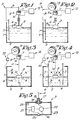
- FIG. 1 shows a receptacle 1 containing a medium 2 with which the system for data transmission cooperates according to the invention.
- This system consists primarily of a mainly and a secondary electrical circuit of which the first one is formed by an autonomous and active measuring device 3 functionning as the signal source ; a freely movable electric conductive element 4, for instance a metallic rod, with which the measuring device 3 is connected and an electrical connection 5 consisting of the rod 4, the measuring device 3, the range capacity 6, a rod 7 and a connection 8, while the secondary circuit is formed by a signal reception unit 9, for instance a magnetic ring core 10, equipped with a toroidal coil 11, through which the electric conductive element 4, without necessarily establishing a physical or galvanic contact, can move freely and a signal processing unit 12 which is connected with a signal reception device 9 by means of the toroidal coil 11.
- a signal reception unit 9 for instance a magnetic ring core 10 equipped with a toroidal coil 11
- a signal processing unit 12 which is connected with a signal reception device 9
- the functioning of this system can easily be deduced from figure 1 and rests on the principle of the functioning of a transformer.
- the signal source 3 creates an electric current which will function as the primary winding of the transformer 9 via the metallic rod 4.
- the magnetic connection with the secondary toroidal coil 11 will be optimal and indifferent to interfering magnetic and/or electric dispersion fields.
- the secondary current which is thus induced in the aforementioned secondary toroidal coil 11 by the transformer's effect, is being amplified in the signal processing unit 12 and processed in a suitable manner.
- FIG 2 another embodiment of a system according to the invention is depicted wherein the electric conductive and free movable element 4 consists of a metallic measuring wire.
- This measuring wire 4 is in this case wound around a position measuring device which is carried out in the shape of a drum 13, which is driven by means of a power device not represented in the figure, as for instance a step motor, a rotary permanent magnet with electromagnetic drive of another appropriate device, one and the other in such way that the measuring device 3 can be moved in a controlled way and that the relation between the rotary movement of the drum 13 and the vertical translation of the measuring device 3 is known.
- a power device not represented in the figure as for instance a step motor, a rotary permanent magnet with electromagnetic drive of another appropriate device, one and the other in such way that the measuring device 3 can be moved in a controlled way and that the relation between the rotary movement of the drum 13 and the vertical translation of the measuring device 3 is known.
- the position measuring device in a preferred embodiment which is carried out in the shape of a drum 13, is being, by means of a direct or indirect electric connection, for instance by means of a connecting network 15, put into galvanic, capacitative or induction contact with the electrically conductive receptacle 1, in such way that the primary electric circuit of the transmission system according to the invention consists of the signal source 3, the electrically conductive measuring wire 4, the position measuring device 14, the connecting network 15 and the dispersion capacity 6 of the capacitor formed by the housing or a part of the housing of the signal source 3 and the electrically conductive receptacle 1.
- the secondary circuit of the transmission system consists of the toroidal coil 11 which is positioned outside the field wherein the measuring device 3 can be moved, whereby this coil 11 is wound on the magnetic ring core 10 through which the measuring wire 4 can be guided without physical or galvanic contact.
- the secondary circuit consists of the signal processing unit 12 which does not necessarily have to be positioned in the immediate proximity of the toroidal coil 11.
- FIG 4 another embodiment of the system according to the invention is shown, in which the aforementioned dispersion capacity 6 is built up between the housing of the signal source 3 and an electrically conductive tube or rod 7 being introduced in the receptacle 1.
- the measuring device 3 as found in figure 5, consists preferrably of a complete or partial electrically conductive housing 16, which on top is equipped with a central passage 17 through which a wire securing element 18 has been installed. Latter is insulated from the housing 16 by means of an element 19.
- one or more sensors 20 are provided for which transmit the signals to an autonomous and active measuring signal receiving unit 21, which in turn transmits the measuring signals to a signal converter 22 which will modulate the signals in an appropriate manner and will transmit the modulated transmission signal, on one hand, to the conductive parts of the housing and on the other hand, to the wire securing element 18, in such way that the primary electriccircuit will be completed through the dispersion capacity 6, on one hand, and the measuring wire 4, on the other hand.
- Aforementioned sensors 20, the measuring signal receiving unit 21 and the signal converter 22 can be supplied individually or jointly with energy, for instance by means of one or more batteries or any other form of power supply. Furthermore the measuring device described above can be completely surrounded by an electrically insulating layer 23, which obviously does not interfere with the dispersion capacity.
- the measuring device 3 can be equipped with a time recording unit and a memory in which according to a specific cyclic process, during a specific period of time the measuring data can be stored together with the time indication.
- the position measuring device 13 will bring the measuring device 3 to the required level of measurement. This position shall in most cases, coincide with the fluid level.
- the position measuring device however can position the measuring device 3 in another position as well, even beneath the fluid's surface, from which the measuring device 3 will then transmit its information.
- the measuring signals be momentarily stored in a memory together with the time indication. After completion of the measurement the position measuring device 13 will in that case pull the measuring device 3 out of the tested fluid and the stored data will be transmitted to the signal processing unit 12.
- the memory storage/transmission cycle In order to synchronize the memory storage/transmission cycle one may for instance make use of a magnet which can be positioned underneath the reception unit 9 and against which the measuring device 3 can be pulled upwards. The memory storage/transmission cycle can then be synchronized by means of an element at hand in the measuring device 3 which reacts to it.
- the system for the synchronization of the memory storage/transmission cycle can also be used to make the measuring device 3 inactive for a specific period of time, with the purpose in mind to increase the lifespan of the power supply.
- a similar controllability of the measuring device can be achieved by equipping the wire securing element 18 in the measuring device with a power or acceleration sensor.
Landscapes
- Physics & Mathematics (AREA)
- General Physics & Mathematics (AREA)
- Fluid Mechanics (AREA)
- Arrangements For Transmission Of Measured Signals (AREA)
- Selective Calling Equipment (AREA)
- Exchange Systems With Centralized Control (AREA)
- Testing Or Calibration Of Command Recording Devices (AREA)
- Circuits Of Receivers In General (AREA)
- Control By Computers (AREA)
- Communication Control (AREA)
- Medicines Containing Material From Animals Or Micro-Organisms (AREA)
- Surgical Instruments (AREA)
Priority Applications (1)
| Application Number | Priority Date | Filing Date | Title |
|---|---|---|---|
| AT88201294T ATE70124T1 (de) | 1987-07-01 | 1988-06-23 | Datenuebertragungssystem. |
Applications Claiming Priority (2)
| Application Number | Priority Date | Filing Date | Title |
|---|---|---|---|
| BE8700738 | 1987-07-01 | ||
| BE8700738A BE1000709A4 (nl) | 1987-07-01 | 1987-07-01 | Inrichting voor de transmissie van gegevens. |
Publications (3)
| Publication Number | Publication Date |
|---|---|
| EP0297662A2 true EP0297662A2 (de) | 1989-01-04 |
| EP0297662A3 EP0297662A3 (en) | 1989-05-24 |
| EP0297662B1 EP0297662B1 (de) | 1991-12-04 |
Family
ID=3882752
Family Applications (1)
| Application Number | Title | Priority Date | Filing Date |
|---|---|---|---|
| EP88201294A Expired - Lifetime EP0297662B1 (de) | 1987-07-01 | 1988-06-23 | Datenübertragungssystem |
Country Status (14)
| Country | Link |
|---|---|
| US (1) | US4983964A (de) |
| EP (1) | EP0297662B1 (de) |
| JP (1) | JPH01280994A (de) |
| AT (1) | ATE70124T1 (de) |
| AU (1) | AU600368B2 (de) |
| BE (1) | BE1000709A4 (de) |
| BR (1) | BR8803231A (de) |
| CA (1) | CA1298378C (de) |
| DE (2) | DE3866608D1 (de) |
| ES (1) | ES2009739T3 (de) |
| GR (2) | GR890300142T1 (de) |
| NO (1) | NO174607C (de) |
| YU (1) | YU47470B (de) |
| ZA (1) | ZA884635B (de) |
Cited By (1)
| Publication number | Priority date | Publication date | Assignee | Title |
|---|---|---|---|---|
| GB2272026A (en) * | 1992-10-29 | 1994-05-04 | William Chilton | Electrical power generation from waves |
Families Citing this family (2)
| Publication number | Priority date | Publication date | Assignee | Title |
|---|---|---|---|---|
| US5602540A (en) * | 1993-06-14 | 1997-02-11 | Simmonds Precision Products Inc. | Fluid gauging apparatus with inductive interrogation |
| DE102009002009A1 (de) | 2009-03-31 | 2010-10-07 | Endress + Hauser Gmbh + Co. Kg | Vorrichtung zur Reduzierung bzw. Minimierung von Störsignalen bei einem Feldgerät der Prozessautomatisierung |
Citations (1)
| Publication number | Priority date | Publication date | Assignee | Title |
|---|---|---|---|---|
| GB2046912A (en) | 1979-05-09 | 1980-11-19 | Edworthy K J | A liquid level detector |
Family Cites Families (14)
| Publication number | Priority date | Publication date | Assignee | Title |
|---|---|---|---|---|
| CH222573A (de) * | 1939-09-29 | 1942-07-31 | Ig Farbenindustrie Ag | Elektromagnetische Messeinrichtung. |
| US2750794A (en) * | 1952-11-07 | 1956-06-19 | George W Downs | Acoustisonde apparatus for measuring and recording physical properties of the sea |
| US3512408A (en) * | 1967-12-08 | 1970-05-19 | Trw Inc | Bathometer |
| US3969941A (en) * | 1973-11-08 | 1976-07-20 | E. Rapp Electronik Gmbh | Level detector for liquids and other flowable masses |
| SU511707A1 (ru) * | 1973-12-12 | 1976-04-25 | Институт Океанологии Им.П.П.Ширшова Ан Союзасср | Индуктивна муфта дл бесконтактной передачи сигналов в морской воде |
| US3974695A (en) * | 1975-08-18 | 1976-08-17 | Sun Oil Company Of Pennsylvania | Double level gauge |
| JPS5482257A (en) * | 1977-12-14 | 1979-06-30 | Tokyo Keiso Kk | System for supervising plurality of tank yard |
| US4309655A (en) * | 1978-06-23 | 1982-01-05 | Lgz Landis & Gyr Zug Ag | Measuring transformer |
| US4263587A (en) * | 1979-04-09 | 1981-04-21 | International Telephone And Telegraph Corporation | Liquid level control system |
| US4515015A (en) * | 1983-02-16 | 1985-05-07 | Magnetrol International, Incorporated | Capacitance level sensor for use with viscous, electrically conductive materials |
| US4571998A (en) * | 1984-07-18 | 1986-02-25 | Kevin Stegner | In-ground tank measuring system |
| DE3447560A1 (de) * | 1984-12-21 | 1986-07-10 | Angewandte Digital Elektronik Gmbh, 2051 Brunstorf | Einrichtung zur beruehrungslosen signal- und energieuebertragung |
| US4676101A (en) * | 1986-09-03 | 1987-06-30 | Walbro Corporation | Capacitance-type material level indicator |
| US4831327A (en) * | 1987-05-01 | 1989-05-16 | Hydro-Quebec | Self-powered electrical measuring system isolated from electrical perturbances |
-
1987
- 1987-07-01 BE BE8700738A patent/BE1000709A4/nl not_active IP Right Cessation
-
1988
- 1988-06-23 ES ES198888201294T patent/ES2009739T3/es not_active Expired - Fee Related
- 1988-06-23 AT AT88201294T patent/ATE70124T1/de not_active IP Right Cessation
- 1988-06-23 DE DE8888201294T patent/DE3866608D1/de not_active Expired - Fee Related
- 1988-06-23 DE DE198888201294T patent/DE297662T1/de active Pending
- 1988-06-23 EP EP88201294A patent/EP0297662B1/de not_active Expired - Lifetime
- 1988-06-28 CA CA000570583A patent/CA1298378C/en not_active Expired - Fee Related
- 1988-06-29 US US07/212,791 patent/US4983964A/en not_active Expired - Fee Related
- 1988-06-29 AU AU18498/88A patent/AU600368B2/en not_active Ceased
- 1988-06-29 ZA ZA884635A patent/ZA884635B/xx unknown
- 1988-06-30 BR BR8803231A patent/BR8803231A/pt not_active IP Right Cessation
- 1988-06-30 NO NO882916A patent/NO174607C/no not_active IP Right Cessation
- 1988-07-01 JP JP63164834A patent/JPH01280994A/ja active Granted
- 1988-07-01 YU YU128288A patent/YU47470B/sh unknown
-
1990
- 1990-03-14 GR GR89300142T patent/GR890300142T1/el unknown
-
1992
- 1992-03-04 GR GR920400378T patent/GR3003955T3/el unknown
Patent Citations (1)
| Publication number | Priority date | Publication date | Assignee | Title |
|---|---|---|---|---|
| GB2046912A (en) | 1979-05-09 | 1980-11-19 | Edworthy K J | A liquid level detector |
Cited By (1)
| Publication number | Priority date | Publication date | Assignee | Title |
|---|---|---|---|---|
| GB2272026A (en) * | 1992-10-29 | 1994-05-04 | William Chilton | Electrical power generation from waves |
Also Published As
| Publication number | Publication date |
|---|---|
| EP0297662B1 (de) | 1991-12-04 |
| DE297662T1 (de) | 1989-10-26 |
| ZA884635B (en) | 1989-06-28 |
| AU600368B2 (en) | 1990-08-09 |
| JPH0519200B2 (de) | 1993-03-16 |
| CA1298378C (en) | 1992-03-31 |
| YU128288A (en) | 1991-01-28 |
| ATE70124T1 (de) | 1991-12-15 |
| NO882916D0 (no) | 1988-06-30 |
| GR890300142T1 (en) | 1990-03-14 |
| BR8803231A (pt) | 1989-01-31 |
| DE3866608D1 (de) | 1992-01-16 |
| GR3003955T3 (de) | 1993-03-16 |
| EP0297662A3 (en) | 1989-05-24 |
| NO174607B (no) | 1994-02-21 |
| AU1849888A (en) | 1989-01-05 |
| NO882916L (no) | 1989-01-02 |
| BE1000709A4 (nl) | 1989-03-14 |
| US4983964A (en) | 1991-01-08 |
| ES2009739A4 (es) | 1989-10-16 |
| JPH01280994A (ja) | 1989-11-13 |
| ES2009739T3 (es) | 1992-06-01 |
| YU47470B (sh) | 1995-10-03 |
| NO174607C (no) | 1994-06-01 |
Similar Documents
| Publication | Publication Date | Title |
|---|---|---|
| US5654639A (en) | Induction measuring device in the presence of metal walls | |
| EP0288998A2 (de) | Eigenversorgtes elektrisches Messsystem, das von elektrischen Störungen isoliert ist | |
| EP0324136A3 (de) | Elektromagnetische Einrichtung für Lagemessungen | |
| CA1298378C (en) | System for data transmission | |
| US5003267A (en) | Measuring electrical impedance of low conductivity samples to monitor microbial growth | |
| JPS6014127A (ja) | 液体レベル遠隔測定用の装置 | |
| US3948100A (en) | Probe for measuring the level of a liquid | |
| JPH0346051B2 (de) | ||
| US4152937A (en) | Liquid level sensor | |
| ES8103874A1 (es) | Un dispositivo para ajustar la inductancia de una bobina | |
| HK87792A (en) | A soil investigation device | |
| CN107102214A (zh) | 具有弹性测试针的小电感金属磁环电感测试工装 | |
| DE69923807D1 (de) | Vorrichtung zur Messung einer mit der Rotation eines Organs zusammenhängenden physikalischen Grösse | |
| DE3775269D1 (de) | Verfahren zur messung elektrischer oder magnetischer wechselfelder und anordnung zur durchfuehrung des verfahrens. | |
| CN2212194Y (zh) | 压力容器内液体液面的传感装置 | |
| SE8603982D0 (sv) | Vorrichtung zur messung und umsetzung physikalischer in elektrische grossen | |
| JPS5646428A (en) | Toner residue detecting system | |
| CN112362945A (zh) | 一种光学电流测量装置 | |
| JPS58144716A (ja) | 液面計 | |
| SU1249308A1 (ru) | Дифференциальный преобразователь линейных перемещений | |
| SU711451A2 (ru) | Устройство дл определени дипольных моментов" | |
| SU818957A1 (ru) | Устройство дл дистанционного кон-ТРОл зА пОСАдКОй СудНА HA КильблОКидОКА | |
| SU1422028A1 (ru) | Устройство дл наклейки тензорезисторов на упругий элемент | |
| SU555822A1 (ru) | Зонд дл опробовани магнетитовых руд | |
| SU840320A1 (ru) | Глубинный уровнемер |
Legal Events
| Date | Code | Title | Description |
|---|---|---|---|
| PUAI | Public reference made under article 153(3) epc to a published international application that has entered the european phase |
Free format text: ORIGINAL CODE: 0009012 |
|
| AK | Designated contracting states |
Kind code of ref document: A2 Designated state(s): AT CH DE ES FR GB GR IT LI LU NL SE |
|
| PUAL | Search report despatched |
Free format text: ORIGINAL CODE: 0009013 |
|
| AK | Designated contracting states |
Kind code of ref document: A3 Designated state(s): AT CH DE ES FR GB GR IT LI LU NL SE |
|
| 17P | Request for examination filed |
Effective date: 19890606 |
|
| ITCL | It: translation for ep claims filed |
Representative=s name: BARZANO'E ZANARDO S.P.A. |
|
| TCAT | At: translation of patent claims filed | ||
| TCNL | Nl: translation of patent claims filed | ||
| EL | Fr: translation of claims filed | ||
| DET | De: translation of patent claims | ||
| 17Q | First examination report despatched |
Effective date: 19900801 |
|
| GRAA | (expected) grant |
Free format text: ORIGINAL CODE: 0009210 |
|
| AK | Designated contracting states |
Kind code of ref document: B1 Designated state(s): AT CH DE ES FR GB GR IT LI LU NL SE |
|
| REF | Corresponds to: |
Ref document number: 70124 Country of ref document: AT Date of ref document: 19911215 Kind code of ref document: T |
|
| REF | Corresponds to: |
Ref document number: 3866608 Country of ref document: DE Date of ref document: 19920116 |
|
| ET | Fr: translation filed | ||
| ITF | It: translation for a ep patent filed | ||
| REG | Reference to a national code |
Ref country code: ES Ref legal event code: FG2A Ref document number: 2009739 Country of ref document: ES Kind code of ref document: T3 |
|
| PLBE | No opposition filed within time limit |
Free format text: ORIGINAL CODE: 0009261 |
|
| STAA | Information on the status of an ep patent application or granted ep patent |
Free format text: STATUS: NO OPPOSITION FILED WITHIN TIME LIMIT |
|
| 26N | No opposition filed | ||
| REG | Reference to a national code |
Ref country code: GR Ref legal event code: FG4A Free format text: 3003955 |
|
| EPTA | Lu: last paid annual fee | ||
| EAL | Se: european patent in force in sweden |
Ref document number: 88201294.1 |
|
| PGFP | Annual fee paid to national office [announced via postgrant information from national office to epo] |
Ref country code: LU Payment date: 20010525 Year of fee payment: 14 Ref country code: FR Payment date: 20010525 Year of fee payment: 14 |
|
| PGFP | Annual fee paid to national office [announced via postgrant information from national office to epo] |
Ref country code: SE Payment date: 20010529 Year of fee payment: 14 |
|
| PGFP | Annual fee paid to national office [announced via postgrant information from national office to epo] |
Ref country code: ES Payment date: 20010612 Year of fee payment: 14 |
|
| PGFP | Annual fee paid to national office [announced via postgrant information from national office to epo] |
Ref country code: AT Payment date: 20010615 Year of fee payment: 14 |
|
| PGFP | Annual fee paid to national office [announced via postgrant information from national office to epo] |
Ref country code: GR Payment date: 20010618 Year of fee payment: 14 |
|
| PGFP | Annual fee paid to national office [announced via postgrant information from national office to epo] |
Ref country code: DE Payment date: 20010622 Year of fee payment: 14 |
|
| PGFP | Annual fee paid to national office [announced via postgrant information from national office to epo] |
Ref country code: NL Payment date: 20010630 Year of fee payment: 14 |
|
| PGFP | Annual fee paid to national office [announced via postgrant information from national office to epo] |
Ref country code: GB Payment date: 20010802 Year of fee payment: 14 |
|
| PGFP | Annual fee paid to national office [announced via postgrant information from national office to epo] |
Ref country code: CH Payment date: 20010816 Year of fee payment: 14 |
|
| REG | Reference to a national code |
Ref country code: GB Ref legal event code: IF02 |
|
| PG25 | Lapsed in a contracting state [announced via postgrant information from national office to epo] |
Ref country code: LU Free format text: LAPSE BECAUSE OF NON-PAYMENT OF DUE FEES Effective date: 20020623 Ref country code: GB Free format text: LAPSE BECAUSE OF NON-PAYMENT OF DUE FEES Effective date: 20020623 Ref country code: AT Free format text: LAPSE BECAUSE OF NON-PAYMENT OF DUE FEES Effective date: 20020623 |
|
| PG25 | Lapsed in a contracting state [announced via postgrant information from national office to epo] |
Ref country code: SE Free format text: LAPSE BECAUSE OF NON-PAYMENT OF DUE FEES Effective date: 20020624 Ref country code: ES Free format text: LAPSE BECAUSE OF NON-PAYMENT OF DUE FEES Effective date: 20020624 |
|
| PG25 | Lapsed in a contracting state [announced via postgrant information from national office to epo] |
Ref country code: LI Free format text: LAPSE BECAUSE OF NON-PAYMENT OF DUE FEES Effective date: 20020630 Ref country code: CH Free format text: LAPSE BECAUSE OF NON-PAYMENT OF DUE FEES Effective date: 20020630 |
|
| PG25 | Lapsed in a contracting state [announced via postgrant information from national office to epo] |
Ref country code: GR Free format text: LAPSE BECAUSE OF NON-PAYMENT OF DUE FEES Effective date: 20021231 |
|
| PG25 | Lapsed in a contracting state [announced via postgrant information from national office to epo] |
Ref country code: NL Free format text: LAPSE BECAUSE OF NON-PAYMENT OF DUE FEES Effective date: 20030101 Ref country code: DE Free format text: LAPSE BECAUSE OF NON-PAYMENT OF DUE FEES Effective date: 20030101 |
|
| EUG | Se: european patent has lapsed | ||
| GBPC | Gb: european patent ceased through non-payment of renewal fee |
Effective date: 20020623 |
|
| REG | Reference to a national code |
Ref country code: CH Ref legal event code: PL |
|
| PG25 | Lapsed in a contracting state [announced via postgrant information from national office to epo] |
Ref country code: FR Free format text: LAPSE BECAUSE OF NON-PAYMENT OF DUE FEES Effective date: 20030228 |
|
| NLV4 | Nl: lapsed or anulled due to non-payment of the annual fee |
Effective date: 20030101 |
|
| REG | Reference to a national code |
Ref country code: FR Ref legal event code: ST |
|
| REG | Reference to a national code |
Ref country code: ES Ref legal event code: FD2A Effective date: 20030711 |
|
| PG25 | Lapsed in a contracting state [announced via postgrant information from national office to epo] |
Ref country code: IT Free format text: LAPSE BECAUSE OF NON-PAYMENT OF DUE FEES Effective date: 20050623 |