EP0297672B1 - Turbokompressor mit luftgekühltem Lager - Google Patents
Turbokompressor mit luftgekühltem Lager Download PDFInfo
- Publication number
- EP0297672B1 EP0297672B1 EP88201329A EP88201329A EP0297672B1 EP 0297672 B1 EP0297672 B1 EP 0297672B1 EP 88201329 A EP88201329 A EP 88201329A EP 88201329 A EP88201329 A EP 88201329A EP 0297672 B1 EP0297672 B1 EP 0297672B1
- Authority
- EP
- European Patent Office
- Prior art keywords
- compressor
- air
- bearing
- housing
- turbo
- Prior art date
- Legal status (The legal status is an assumption and is not a legal conclusion. Google has not performed a legal analysis and makes no representation as to the accuracy of the status listed.)
- Expired - Lifetime
Links
- 239000012530 fluid Substances 0.000 claims abstract description 7
- 238000001816 cooling Methods 0.000 claims abstract description 6
- 230000008878 coupling Effects 0.000 claims 1
- 238000010168 coupling process Methods 0.000 claims 1
- 238000005859 coupling reaction Methods 0.000 claims 1
- 239000003973 paint Substances 0.000 abstract 1
- 239000007921 spray Substances 0.000 abstract 1
- 239000003570 air Substances 0.000 description 27
- 239000012080 ambient air Substances 0.000 description 1
- 230000000694 effects Effects 0.000 description 1
- 230000002028 premature Effects 0.000 description 1
Images

Classifications
-
- F—MECHANICAL ENGINEERING; LIGHTING; HEATING; WEAPONS; BLASTING
- F04—POSITIVE - DISPLACEMENT MACHINES FOR LIQUIDS; PUMPS FOR LIQUIDS OR ELASTIC FLUIDS
- F04D—NON-POSITIVE-DISPLACEMENT PUMPS
- F04D17/00—Radial-flow pumps, e.g. centrifugal pumps; Helico-centrifugal pumps
- F04D17/08—Centrifugal pumps
- F04D17/10—Centrifugal pumps for compressing or evacuating
- F04D17/12—Multi-stage pumps
- F04D17/122—Multi-stage pumps the individual rotor discs being, one for each stage, on a common shaft and axially spaced, e.g. conventional centrifugal multi- stage compressors
-
- F—MECHANICAL ENGINEERING; LIGHTING; HEATING; WEAPONS; BLASTING
- F04—POSITIVE - DISPLACEMENT MACHINES FOR LIQUIDS; PUMPS FOR LIQUIDS OR ELASTIC FLUIDS
- F04D—NON-POSITIVE-DISPLACEMENT PUMPS
- F04D25/00—Pumping installations or systems
- F04D25/02—Units comprising pumps and their driving means
-
- F—MECHANICAL ENGINEERING; LIGHTING; HEATING; WEAPONS; BLASTING
- F04—POSITIVE - DISPLACEMENT MACHINES FOR LIQUIDS; PUMPS FOR LIQUIDS OR ELASTIC FLUIDS
- F04D—NON-POSITIVE-DISPLACEMENT PUMPS
- F04D29/00—Details, component parts, or accessories
- F04D29/26—Rotors specially for elastic fluids
- F04D29/266—Rotors specially for elastic fluids mounting compressor rotors on shafts
-
- F—MECHANICAL ENGINEERING; LIGHTING; HEATING; WEAPONS; BLASTING
- F04—POSITIVE - DISPLACEMENT MACHINES FOR LIQUIDS; PUMPS FOR LIQUIDS OR ELASTIC FLUIDS
- F04D—NON-POSITIVE-DISPLACEMENT PUMPS
- F04D29/00—Details, component parts, or accessories
- F04D29/58—Cooling; Heating; Diminishing heat transfer
- F04D29/582—Cooling; Heating; Diminishing heat transfer specially adapted for elastic fluid pumps
- F04D29/584—Cooling; Heating; Diminishing heat transfer specially adapted for elastic fluid pumps cooling or heating the machine
Definitions
- the invention relates to a turbo-compressor air supply system as described in the preamble of claim 1.
- both the first (upper) and the second (lower) bearing of the turbine shaft are enclosed in the turbo-compressor housing.
- the heat, developed in the immediate environment of the turbo shaft bearings cannot be dissipated and will build up to high levels.
- the upper bearing shaft being the hottest as warm air tends to rise. It has, for example, been found that the operating temperature in the vicinity of the upper turbine shaft bearing can reach 97°C or even higher levels. Such temperature often exceed the performance specifications of the bearing and lead to premature bearing failure.
- the invention aims to obviate this drawback and this aim is achieved by means of the measures as described in the characterizing clause of the main claim.
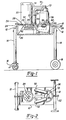
- a portable air supply system embodying the present invention includes a hollow box-like housing designated generally 10 having cross frame members 12 fixedly secured to its opposite ends and projecting outwardly beyond the opposite sides of the box as best seen in Figure 2. From each end of each cross frame member 12, vertical legs project downwardly, one set of legs 14 having caster mounted wheels mounted at the lower end, while the other set of legs 14 rotatably carries a somewhat larger, non-steerable set of wheels 18.
- Housing 10 is a simple rectangular box formed with a top wall 20, opposed sidewalls 22, end walls 24 and a bottom wall 26.
- Bottom wall 26 is removable, being held to the side and end walls 22, 24 by bolts, not shown, to provide access to the chamber 28 within the housing.
- An electric drive motor 30 is mounted upon the top wall of the housing with its drive shaft 32 disposed vertically and projecting downwardly through an opening 34 in top wall 20.
- a multi-stage turbo-compressor 36 is also fixedly mounted upon top wall 20 with its drive shaft 38 projecting downwardly through an opening 40 in top wall 20, as best seen in Figure 1. Rotation of the shaft of drive motor 30 is transmitted to the shaft 38 of turbo-compressor 36 by a belt and pulley drive designated generally 42 located within chamber 28.
- Bottom wall 26 is formed with two reasonably large openings 46, 48.
- a pair of open ended vertically disposed tubular pipes 49 project vertically through housing 10 and are fixedly secured within tightly fitting openings, not shown, in top wall 20 and bottom wall 26 of the housing.
- a flexible wall tube 50 is clamped to the upper end of each pipe 49 to connect the pipe to extensions 52 of the air inlets to compressor 36.
- Drive motor 30 is mounted upon a plate 54 which is slidable relative to top wall 20 of the housing.
- An adjustment bolt 56 is operable to position the motor longitudinally of the housing to thereby regulate the tension of the drive belt of the belt and pulley drive 42.
- plate 54 is clamped in position to top wall 20 by bolts not shown.
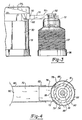
- FIG. 3 a detailed view of the upper end of compressor 36, there is provided a bearing housing 72 which projects from the compressor housing 37.
- Compressor housing 37 is formed with a sleeve 80 which encases bearing housing 72.
- the bearing housing 72 is disposed concentrically around and spaced from an upper projecting portion of the drive shaft 38.
- the bearing 34 is mounted onto shaft 38 by means of a nut 41.
- An air space 78 is formed between at least part of the inside of sleeve 80 and the inside of bearing housing 72.
- Air space 78 is further defined by cap 92 and top plate 94 which, respectively, seal off the top and bottom of air space 78.
- a shaft seal 96 is disposed between the top of shaft 38 and cap 92.
- Sleeve 80 further comprises an air inlet 86 and air outlets 88 as can be seen in Figure 4.
- a plurality of air inlets 84 are formed in the top of the casing 31 which encloses drive motor 30. As can be seen from the arrows, which indicate air flow direction, ambient air enters first the plurality of air inlets 84 and the motor housing 31. An air outlet 90 adjacent the top of motor casing 31 is provided. A means of fluid communication in the form of a hollow tube 74 connects air outlet 90 and air inlets 86 formed in sleeve 80. By means of hollow tube 74, a portion of a stream of air introduced into motor casing 31 by means of the plurality of inlets 84 is diverted around bearing housing 72. It flows through air space 78 therein and then exits by means of air outlet 88. This flow of air is indicated by the arrows in Figures 3 and 4. By means of the portion of air which is diverted around the bearing housing 72, the environment in which the bearing 34 operates is made cooler.
- the operating temperature of the upper shaft bearing 34 of the turbo-compressor of the instant invention under actual operating conditions has been found to be approximately 82°C. This represents a temperature drop of approximately 15°C attributable to the design of the air cooled turbo-compressor of the instant invention.
- the temperature drop is largely due to two factors. First, by extending turbine shaft 38 so that it projects out of the upper end of compressor housing 36, the bearing is no longer subjected to much of the heat generated by the operation of the turbo-compressor. Secondly by diverting some of the air flowing through the motor casing 31 around the bearing housing 72, a further cooling effect is achieved.
- the herein invention may comprise additional structures, such as two piece sleeve 82 which, as depicted in Figure 5, is mounted over the end of the hollow tube 70 adjacent air outlet 90 disposed in motor casing 31.
- Sleeve 82 provides a means of adjusting the length of hollow pipe 74 to accommodate different length drive belts or different pulley sizes used in the operation of a turbo-compressor 37.
Landscapes
- Engineering & Computer Science (AREA)
- Mechanical Engineering (AREA)
- General Engineering & Computer Science (AREA)
- Physics & Mathematics (AREA)
- Thermal Sciences (AREA)
- Structures Of Non-Positive Displacement Pumps (AREA)
- Nozzles (AREA)
- Supercharger (AREA)
- Compressor (AREA)
- Fats And Perfumes (AREA)
- Acyclic And Carbocyclic Compounds In Medicinal Compositions (AREA)
Claims (5)
einen Antriebsmotor (30) mit:
einem den Motor (30) umschließenden Gehäuse (31),
einer aus dem Gehäuse (31) heraustretenden Antriebswelle (32),
mit dem Gehäuse (31) in Strömungsverbindung stehende Lufteinlaßmittel (84),
einen Luftauslaß (90) im Gehäuse,
einen Turbokompressor (36), der enthält:
ein Gehäuse (37),
eine mit einem ersten und einem zweiten Ende aus dem Gehäuse (37) heraustretende Antriebswelle (38),
ein erstes (34) und ein zweites Lager für die Antriebswelle (38);
ein Antriebsverbindungsglied (42), das die Antriebswelle (32) des Antriebsmotors mit dem heraustretenden zweiten Ende der Antriebswelle (38) des Kompressors koppelt, um den Antrieb des Turbokompressors durch den Motor zu ermöglichen,
dadurch gekennzeichnet, daß das erste Lager (34) der Antriebswelle (38) des Turbokompressors in einem Lagergehäuse (72) eingeschlossen ist, das von dem Kompressorgehäuse (37) absteht und konzentrisch um das und in Abstand von dem ersten heraustretenden Ende der Antriebswelle (38) angeordnet ist, daß das Lagergehäuse einen das Lager umgebenden Innenraum aufweist, daß eine Strömungsverbindung (74) vorgesehen ist zur Zuführung eines Kühlluftstroms unter einem positiven Druck zum Lagergehäuse (72), und daß der Innenraum des Lagergehäuses (72) in Strömungsverbindung mit dem Luftauslaß (90) im Gehäuse (31) des Antriebsmotors steht, um wenigstens einen Teil der während des Betriebs durch die Lufteinlaßmittel (84) eintretenden Luft dem Lagergehäuse zur Kühlung des Lagers zuzuführen.
Priority Applications (1)
| Application Number | Priority Date | Filing Date | Title |
|---|---|---|---|
| AT88201329T ATE72599T1 (de) | 1987-06-29 | 1988-06-27 | Turbokompressor mit luftgekuehltem lager. |
Applications Claiming Priority (4)
| Application Number | Priority Date | Filing Date | Title |
|---|---|---|---|
| US07/067,305 US4780056A (en) | 1987-06-29 | 1987-06-29 | Turbo-compressor having air cooled bearing |
| US67305 | 1987-06-29 | ||
| US07/208,590 US4925368A (en) | 1987-06-29 | 1988-06-20 | Turbo-compressor having air-cooled bearing |
| CA000609481A CA1337343C (en) | 1987-06-29 | 1989-08-25 | Staged turbo compressor with flanged and air cooled drive shaft |
Publications (3)
| Publication Number | Publication Date |
|---|---|
| EP0297672A2 EP0297672A2 (de) | 1989-01-04 |
| EP0297672A3 EP0297672A3 (en) | 1989-09-13 |
| EP0297672B1 true EP0297672B1 (de) | 1992-02-12 |
Family
ID=39968565
Family Applications (1)
| Application Number | Title | Priority Date | Filing Date |
|---|---|---|---|
| EP88201329A Expired - Lifetime EP0297672B1 (de) | 1987-06-29 | 1988-06-27 | Turbokompressor mit luftgekühltem Lager |
Country Status (10)
| Country | Link |
|---|---|
| US (2) | US4780056A (de) |
| EP (1) | EP0297672B1 (de) |
| JP (1) | JP2731396B2 (de) |
| AT (1) | ATE72599T1 (de) |
| AU (1) | AU3848089A (de) |
| CA (2) | CA1335091C (de) |
| DE (1) | DE3868362D1 (de) |
| ES (1) | ES2028990T3 (de) |
| FI (1) | FI905409A7 (de) |
| WO (1) | WO1989012753A1 (de) |
Families Citing this family (6)
| Publication number | Priority date | Publication date | Assignee | Title |
|---|---|---|---|---|
| US4780056A (en) * | 1987-06-29 | 1988-10-25 | Can-Am Engineered Products, Inc. | Turbo-compressor having air cooled bearing |
| US4869641A (en) * | 1987-09-28 | 1989-09-26 | Accuspray, Inc. | Compressor |
| US5161939A (en) * | 1991-07-12 | 1992-11-10 | Turbo Concepts, Inc. | Air compression system |
| US6773237B2 (en) * | 2001-08-27 | 2004-08-10 | Coleman Powermate, Inc. | Air compressor workbench |
| US7631725B2 (en) * | 2006-10-06 | 2009-12-15 | Ingersoll Rand Company | Exhaust system |
| WO2011050230A1 (en) * | 2009-10-22 | 2011-04-28 | Bunnell Michael H | Paint spray booth system |
Family Cites Families (18)
| Publication number | Priority date | Publication date | Assignee | Title |
|---|---|---|---|---|
| BE422494A (de) * | ||||
| US2733001A (en) * | 1956-01-31 | Apparatus for cooling the bearings | ||
| CA712470A (en) * | 1965-06-29 | Canadian Westinghouse Company Limited | Fans | |
| US2131691A (en) * | 1937-09-22 | 1938-09-27 | Bertrand A Parkes | Fan or blower construction |
| US2601030A (en) * | 1948-11-29 | 1952-06-17 | Petersen Oven Co | Centrifugal blower |
| US2826354A (en) * | 1957-05-13 | 1958-03-11 | Vivian A Field | Portable air compressors |
| DE1265011B (de) * | 1960-03-25 | 1968-03-28 | Aix En Provence | Turbokompressor zur Erzeugung erwaermter Luft zum Spritzen von Farben |
| US3069071A (en) * | 1961-03-03 | 1962-12-18 | Westinghouse Electric Corp | Fans having radial flow rotors in axial flow casings |
| US3101890A (en) * | 1961-05-29 | 1963-08-27 | Westinghouse Electric Corp | Fans having radial flow rotors in axial flow casings |
| US3145913A (en) * | 1961-11-03 | 1964-08-25 | Dolz Heinrich | Multi-stage turbo-compressors |
| US3289923A (en) * | 1964-10-30 | 1966-12-06 | American Air Filter Co | Multi-stage pump |
| US3320895A (en) * | 1965-01-14 | 1967-05-23 | Richard A Peterson | Spraying apparatus with pump and motor adjustment |
| US3224667A (en) * | 1965-01-29 | 1965-12-21 | Mc Graw Edison Co | Multi-stage air blower |
| GB1492644A (en) * | 1976-02-06 | 1977-11-23 | Mcivor & Son Ltd R | Blower/exhauster |
| US4341506A (en) * | 1979-08-14 | 1982-07-27 | Gutehoffnungshutte Sterkrade A.G. | Apparatus for the generation of compressed air |
| EP0158681B1 (de) * | 1983-09-22 | 1991-11-06 | Ebara Corporation | Rotierende gasmaschine |
| US4729722A (en) * | 1986-11-05 | 1988-03-08 | Can-Am Engineered Products, Inc. | Noise suppressor for turbo-compressor |
| US4780056A (en) * | 1987-06-29 | 1988-10-25 | Can-Am Engineered Products, Inc. | Turbo-compressor having air cooled bearing |
-
1987
- 1987-06-29 US US07/067,305 patent/US4780056A/en not_active Expired - Lifetime
-
1988
- 1988-06-20 US US07/208,590 patent/US4925368A/en not_active Expired - Fee Related
- 1988-06-27 ES ES198888201329T patent/ES2028990T3/es not_active Expired - Lifetime
- 1988-06-27 DE DE8888201329T patent/DE3868362D1/de not_active Expired - Fee Related
- 1988-06-27 EP EP88201329A patent/EP0297672B1/de not_active Expired - Lifetime
- 1988-06-27 AT AT88201329T patent/ATE72599T1/de not_active IP Right Cessation
- 1988-06-27 JP JP63159029A patent/JP2731396B2/ja not_active Expired - Fee Related
- 1988-06-28 CA CA000570633A patent/CA1335091C/en not_active Expired - Fee Related
-
1989
- 1989-06-20 WO PCT/US1989/002688 patent/WO1989012753A1/en not_active Ceased
- 1989-06-20 AU AU38480/89A patent/AU3848089A/en not_active Abandoned
- 1989-06-20 FI FI905409A patent/FI905409A7/fi not_active IP Right Cessation
- 1989-08-25 CA CA000609481A patent/CA1337343C/en not_active Expired - Fee Related
Also Published As
| Publication number | Publication date |
|---|---|
| FI905409A0 (fi) | 1990-11-01 |
| EP0297672A2 (de) | 1989-01-04 |
| FI905409A7 (fi) | 1990-11-01 |
| CA1335091C (en) | 1995-04-04 |
| WO1989012753A1 (en) | 1989-12-28 |
| US4925368A (en) | 1990-05-15 |
| US4780056A (en) | 1988-10-25 |
| EP0297672A3 (en) | 1989-09-13 |
| AU3848089A (en) | 1990-01-12 |
| JP2731396B2 (ja) | 1998-03-25 |
| JPS6473132A (en) | 1989-03-17 |
| ATE72599T1 (de) | 1992-02-15 |
| DE3868362D1 (de) | 1992-03-26 |
| CA1337343C (en) | 1995-10-17 |
| ES2028990T3 (es) | 1992-07-16 |
Similar Documents
| Publication | Publication Date | Title |
|---|---|---|
| US6668565B1 (en) | Rack-mounted equipment cooling | |
| US6027406A (en) | Centrifugal fan unit with vertical rotation axis | |
| JP5274544B2 (ja) | 熱電式の温度調節装置 | |
| US4321803A (en) | Multiple air passage condenser | |
| US5062280A (en) | Air conditioning apparatus | |
| US5639222A (en) | Close coupled series turbine mounting | |
| CN110344925B (zh) | 一种可调式汽车温控水箱 | |
| CA2231913C (en) | Centrifugal fan unit with vertical rotation axis | |
| US6924572B2 (en) | Weather protected modular motor enclosure | |
| US5720599A (en) | Vertical arrangement of a dual heat exchanger/fan assembly with an air compressor | |
| CA1280373C (en) | Noise suppressor for turbo-compressor | |
| KR20010101323A (ko) | 과급기를 구비하는 연소 기관 부속 장치 | |
| US4866320A (en) | Fan assembly | |
| US4264818A (en) | Single-tank X-ray generator | |
| US4780056A (en) | Turbo-compressor having air cooled bearing | |
| US2504798A (en) | Unit heater | |
| US4869641A (en) | Compressor | |
| US2268046A (en) | Blower | |
| GB2151394A (en) | Gas transport laser apparatus with axial gas flow | |
| GB2352509A (en) | Air duct component | |
| JP3426904B2 (ja) | 塗料噴射器 | |
| CN217545367U (zh) | 一种散热效果好的配电箱 | |
| GB2088960A (en) | Rotary Positive-displacement Gas Compressors | |
| US2773639A (en) | Draft inducers | |
| CN202915671U (zh) | 风循环微波干燥设备 |
Legal Events
| Date | Code | Title | Description |
|---|---|---|---|
| PUAI | Public reference made under article 153(3) epc to a published international application that has entered the european phase |
Free format text: ORIGINAL CODE: 0009012 |
|
| AK | Designated contracting states |
Kind code of ref document: A2 Designated state(s): AT BE CH DE ES FR GB GR IT LI LU NL SE |
|
| PUAL | Search report despatched |
Free format text: ORIGINAL CODE: 0009013 |
|
| RHK1 | Main classification (correction) |
Ipc: F04D 25/02 |
|
| AK | Designated contracting states |
Kind code of ref document: A3 Designated state(s): AT BE CH DE ES FR GB GR IT LI LU NL SE |
|
| 17P | Request for examination filed |
Effective date: 19890823 |
|
| 17Q | First examination report despatched |
Effective date: 19901001 |
|
| GRAA | (expected) grant |
Free format text: ORIGINAL CODE: 0009210 |
|
| AK | Designated contracting states |
Kind code of ref document: B1 Designated state(s): AT BE CH DE ES FR GB GR IT LI LU NL SE |
|
| PG25 | Lapsed in a contracting state [announced via postgrant information from national office to epo] |
Ref country code: SE Effective date: 19920212 Ref country code: NL Effective date: 19920212 Ref country code: LI Effective date: 19920212 Ref country code: GR Free format text: LAPSE BECAUSE OF FAILURE TO SUBMIT A TRANSLATION OF THE DESCRIPTION OR TO PAY THE FEE WITHIN THE PRESCRIBED TIME-LIMIT Effective date: 19920212 Ref country code: CH Effective date: 19920212 Ref country code: BE Effective date: 19920212 Ref country code: AT Effective date: 19920212 |
|
| REF | Corresponds to: |
Ref document number: 72599 Country of ref document: AT Date of ref document: 19920215 Kind code of ref document: T |
|
| REF | Corresponds to: |
Ref document number: 3868362 Country of ref document: DE Date of ref document: 19920326 |
|
| ITF | It: translation for a ep patent filed | ||
| REG | Reference to a national code |
Ref country code: CH Ref legal event code: PL |
|
| ET | Fr: translation filed | ||
| PG25 | Lapsed in a contracting state [announced via postgrant information from national office to epo] |
Ref country code: LU Free format text: LAPSE BECAUSE OF NON-PAYMENT OF DUE FEES Effective date: 19920630 |
|
| NLV1 | Nl: lapsed or annulled due to failure to fulfill the requirements of art. 29p and 29m of the patents act | ||
| REG | Reference to a national code |
Ref country code: ES Ref legal event code: FG2A Ref document number: 2028990 Country of ref document: ES Kind code of ref document: T3 |
|
| PLBE | No opposition filed within time limit |
Free format text: ORIGINAL CODE: 0009261 |
|
| STAA | Information on the status of an ep patent application or granted ep patent |
Free format text: STATUS: NO OPPOSITION FILED WITHIN TIME LIMIT |
|
| 26N | No opposition filed | ||
| PGFP | Annual fee paid to national office [announced via postgrant information from national office to epo] |
Ref country code: FR Payment date: 19960628 Year of fee payment: 9 |
|
| PG25 | Lapsed in a contracting state [announced via postgrant information from national office to epo] |
Ref country code: FR Free format text: LAPSE BECAUSE OF NON-PAYMENT OF DUE FEES Effective date: 19980227 |
|
| REG | Reference to a national code |
Ref country code: FR Ref legal event code: ST |
|
| REG | Reference to a national code |
Ref country code: FR Ref legal event code: ST |
|
| REG | Reference to a national code |
Ref country code: GB Ref legal event code: IF02 |
|
| PGFP | Annual fee paid to national office [announced via postgrant information from national office to epo] |
Ref country code: GB Payment date: 20050614 Year of fee payment: 18 |
|
| PGFP | Annual fee paid to national office [announced via postgrant information from national office to epo] |
Ref country code: ES Payment date: 20050623 Year of fee payment: 18 |
|
| PG25 | Lapsed in a contracting state [announced via postgrant information from national office to epo] |
Ref country code: IT Free format text: LAPSE BECAUSE OF NON-PAYMENT OF DUE FEES;WARNING: LAPSES OF ITALIAN PATENTS WITH EFFECTIVE DATE BEFORE 2007 MAY HAVE OCCURRED AT ANY TIME BEFORE 2007. THE CORRECT EFFECTIVE DATE MAY BE DIFFERENT FROM THE ONE RECORDED. Effective date: 20050627 |
|
| PGFP | Annual fee paid to national office [announced via postgrant information from national office to epo] |
Ref country code: DE Payment date: 20050629 Year of fee payment: 18 |
|
| PG25 | Lapsed in a contracting state [announced via postgrant information from national office to epo] |
Ref country code: GB Free format text: LAPSE BECAUSE OF NON-PAYMENT OF DUE FEES Effective date: 20060627 |
|
| PG25 | Lapsed in a contracting state [announced via postgrant information from national office to epo] |
Ref country code: ES Free format text: LAPSE BECAUSE OF NON-PAYMENT OF DUE FEES Effective date: 20060628 |
|
| PG25 | Lapsed in a contracting state [announced via postgrant information from national office to epo] |
Ref country code: DE Free format text: LAPSE BECAUSE OF NON-PAYMENT OF DUE FEES Effective date: 20070103 |
|
| GBPC | Gb: european patent ceased through non-payment of renewal fee |
Effective date: 20060627 |
|
| REG | Reference to a national code |
Ref country code: ES Ref legal event code: FD2A Effective date: 20060628 |