EP0298258A1 - Treibkeilriemen - Google Patents
Treibkeilriemen Download PDFInfo
- Publication number
- EP0298258A1 EP0298258A1 EP88108942A EP88108942A EP0298258A1 EP 0298258 A1 EP0298258 A1 EP 0298258A1 EP 88108942 A EP88108942 A EP 88108942A EP 88108942 A EP88108942 A EP 88108942A EP 0298258 A1 EP0298258 A1 EP 0298258A1
- Authority
- EP
- European Patent Office
- Prior art keywords
- metal
- power transmitting
- recesses
- block
- belt according
- Prior art date
- Legal status (The legal status is an assumption and is not a legal conclusion. Google has not performed a legal analysis and makes no representation as to the accuracy of the status listed.)
- Withdrawn
Links
- 239000002184 metal Substances 0.000 claims abstract description 155
- 230000008093 supporting effect Effects 0.000 claims abstract description 37
- 238000005452 bending Methods 0.000 claims description 7
- 239000000463 material Substances 0.000 claims description 5
- 239000000956 alloy Substances 0.000 claims description 2
- 229910045601 alloy Inorganic materials 0.000 claims description 2
- 230000005540 biological transmission Effects 0.000 description 2
- 238000005461 lubrication Methods 0.000 description 2
- 230000013011 mating Effects 0.000 description 2
- 230000000452 restraining effect Effects 0.000 description 2
- 229920001875 Ebonite Polymers 0.000 description 1
- 229940000425 combination drug Drugs 0.000 description 1
- 230000007423 decrease Effects 0.000 description 1
- 239000013536 elastomeric material Substances 0.000 description 1
- 238000010030 laminating Methods 0.000 description 1
- 230000002265 prevention Effects 0.000 description 1
- 230000002035 prolonged effect Effects 0.000 description 1
- 229920003002 synthetic resin Polymers 0.000 description 1
- 239000000057 synthetic resin Substances 0.000 description 1
Images




Classifications
-
- F—MECHANICAL ENGINEERING; LIGHTING; HEATING; WEAPONS; BLASTING
- F16—ENGINEERING ELEMENTS AND UNITS; GENERAL MEASURES FOR PRODUCING AND MAINTAINING EFFECTIVE FUNCTIONING OF MACHINES OR INSTALLATIONS; THERMAL INSULATION IN GENERAL
- F16G—BELTS, CABLES, OR ROPES, PREDOMINANTLY USED FOR DRIVING PURPOSES; CHAINS; FITTINGS PREDOMINANTLY USED THEREFOR
- F16G5/00—V-belts, i.e. belts of tapered cross-section
- F16G5/16—V-belts, i.e. belts of tapered cross-section consisting of several parts
Definitions
- the present invention relates to a power transmitting V-belt and, more particularly, to a power transmitting V-belt which is used in combination with a variable-diameter V-pulley.
- V-belts which are used in combination with variable-diameter V-pulleys for vehicular V-belt type continuously variable transmissions, for example, are known from U.S. Patent No. 4,552,548.
- the V-belt known from this patent is of the type having a multiplicity of V-shaped metal blocks which are connected with each other and which are provided with supporting surfaces for restraining and supporting an endless metal band thereon. Adjacent ones of the metal blocks can rotate relatively to each other around respective axes which extend in the widthwise direction of the metal band.
- the axis around which the V-shaped metal block can rotate relatively to its adjacent metal block is located apart from the block contact surface of the metal band carried on the supporting surfaces of these metal blocks to a position where at the time of engagement of the V-belt with a V-pulley the axis comes closer to the center of the pulley than the block contact surface of the metal band.
- the adjacent metal blocks perform a relative rotation with respect to each other around said axis and as a result the clearance between the blocks at positions thereof where the supporting surfaces are located or of a distance farther from the center of V-pulley than the axis increases or decreases largely.
- This causes slip between the supporting surface of the metal block and the block contact surface of the metal band which is carried on said supporting surface to accelerate wear of these mating surfaces and generate slackening of the band on the blocks, disadvantageously lowering the durability of the V-belt.
- the present invention has been proposed in view of the afore-mentioned problems residing in the prior art and its purpose is to provide a power transmitting V-belt which would not allow a large slip to occur between the metal band and the metal blocks and therefore permit only a small amount of wear to appear in the metal band and the metal blocks even after long time of use, thus making the power transmission totally very efficient.
- an axis around which adjacent v-shaped metal blocks rotate relatively to each other is substantially located on a block contact surface of the metal band which comes into contact with supporting surfaces of the metal blocks.
- a V-belt B according to this embodiment comprises a metal band 1 formed by laminating a plurality of endless metal band elements, a multiplicity of V-shaped metal blocks 2, 2 ... which are lined to one another via cylindrical roller members 4, 4 ... interposed therebetween so as to extend in the longitudinal direction of the metal band 1 for supporting the lower surface or block contact surface 1a of the metal band 1, and stopper members 3, 3 ... made of wire material adapted to restrain the metal band 1 onto the metal blocks 2, 2 ... by engaging respective opposite ends thereof in respective pairs of left and right engaging grooves 2f, 2f provided on the V-shaped metal blocks.
- Each V-shaped metal block 2 is formed on opposite side surfaces thereof facing in the longitudinal direction of the metal band 1 with respective pairs of semi-cylindrical recesses 2a, 2a and 2b, 2b with a distance between the recesses of each pair in the widthwise direction of the metal band 1.
- Each of the metal blocks 2, 2 ... further has on one of said opposite side surfaces, on which one pair of recesses 2b, 2b are provided, an inclined surface 2c formed so as to provide a spacing against the adjacent metal block 2 which becomes larger as the distance from the recesses 2b, 2b increases.
- a recessed groove, unnumbered, having an upper side open is formed on an upper portion of each V-shaped metal block 2, that is, on a wall portion thereof which is located on a side opposite or remote from a center C of V-pulley P (Fig. 1) when the V-belt B engages the V-pulley P.
- the bottom of this recessed groove serves as a supporting surface 2d for supporting the block contact surface 1a of the metal band 1 thereon.
- lateral opposite side surfaces of the V-shaped metal block 2 are formed to include inclined surfaces 2e, 2e placed in engagement with the V-shaped groove of V-pulley P.
- adjacent V-shaped metal blocks 2, 2 achieve their mutual connection by interposing the roller members 4, 4 between the pairs of recesses 4a, 4a and 4b, 4b which are opposed to each other in assembly and these adjacent metal blocks 2, 2 can rotate relatively to each other around the axis o of the roller members 4, 4.
- the axis around which the metal blocks 2, 2 perform relative rotation coincides with the axis of roller members 4, 4 in this embodiment.
- the axis of relative rotation of the metal blocks is substantially located on the block contact surface 1a of the metal band 1 which is restrained and mounted onto the supporting surfaces 2d of the metal blocks 2 by means of the stopper members 3.
- the respective pairs of semi-cylindrical recesses 2a, 2a and 2b, 2b are constructed in such a special manner that their center lines are substantially located on the mounting surface 2d or its extension plane.
- the afore-mentioned recesses 2a, 2b may be formed of a larger radius than that of the roller members 4 in order to give an automatic centering action therebetween. Even in this type of arrangement, the recesses 2a, 2b are determined their positions on the metal block 2 such that the axis of the roller member 4 comes substantially on the block contact surface 1a of the metal band 1.
- each roller member 4 within the recess 2a, 2b is restricted by opposite axial ends of the roller member 4 abutting against the end surfaces of the semi-cylindrical recess 2a, 2b.
- the adjacent two metal blocks 2, 2 rotate relatively to each other around said axis o thereby to cause the clearance between lower parts of the adjacent metal blocks 2, 2, that is, the clearance between the inclined surface 2c of one metal block 2 and the opposed surface of the other metal block 2 as located close to the center C of V-pulley P, to be reduced and simultaneously the clearance between the upper parts of those blocks 2, 2, that is, the clearance between portions of the blocks remote from the pulley center C, to be increased.
- the block contact surface 1a of the metal band 1 which is restrained and supported onto the supporting surfaces 2d, 2d of the V-shaped metal blocks 2, 2 keeps its coincident relation with the axis of such relative rotation and the clearance between the blocks 2, 2 at their portions provided with the supporting surfaces 2d, 2d do not change so that no substantial slip occurs between the supporting surfaces and the block contact surface and accordingly the metal band 1 is allowed to smoothly follow the bending run of the metal blocks 2, 2 ... around the center C of V-pulley P while holding an abutting state at its block contact surface 1a against the supporting surfaces 2d, 2d ... without causing slip.
- Figs. 4 and 5 show a V-shaped metal block 12 constituting a V-belt according to a second embodiment.
- respective one semi-cylindrical recesses 12a, 12b are formed on opposite side surfaces of the metal block 12 at laterally central portions thereof, which is different from the foregoing embodiment.
- one roller member 14 engages in the opposed recesses 12a, 12b of two adjacent metal blocks in a manner to be interposed therebetween.
- a pair of left and right metal bands 11, 11 are used in this embodiment and they are restrained and mounted onto a pair of left and right supporting surfaces 12d, 12d, respectively, by stopper members, not shown.
- the mounting surfaces 12d, 12d are provided on the metal block 12 so as to interpose the recesses 12a, 12b therebetween.
- the recesses 12a, 12b are formed to have a larger radius than that of the roller member 14 and are located on the metal block 12 at such positions that when assembled the roller member 14 engaged in the recesses has its axis o placed coincident substantially with block contact surfaces 11a, 11a of the metal bands 11, 11 which abut against the supporting surfaces 12d, 12d of the metal block 12.
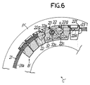
- FIGS. 6 - 14 show a thrid embodiment.
- a V-belt B' according to this embodiment is formed by an appropriate combination of two kinds of V-shaped metal blocks which are lined with each other.
- V-shaped metal blocks according to this embodiment comprise a first metal block 22 which is shown in detail in Figs. 7 - 10 and a second metal block 32 shown in detail in Figs. 11 - 14.
- the first metal block 22 is formed with a pair of semi-cylindrical recesses 22a, 22a on one of opposite side surfaces as viewed in the longitudinal direction of a metal band 21.
- the pair of recesses 22a, 22a are distanced from each other in the widthwise direction of the metal band 21.
- On the other side surface of the block 22 are formed a pair of semi-cylindrical projections 22g, 22g having a widthwise spacing therebetween like the recesses 22a, 22a.
- the first metal block 22 has a supporting surface 22d for carrying thereon a block contact surface 21a of the metal band 21 and this supporting surface 22d is formed into an arcuate surface having a radius equal or approximate to the minimum bending radius R of the metal band 21 which corresponds to the minimum effective radius of a V-pulley P'.
- the first metal block 22 is further formed with a pair of oil feed grooves 22h, 22h with a widthwise spacing therebetween, as shown in Fig. 7, for lubrication of relative rotating parts of the block, on that side surface which includes the recesses 22a, 22a.
- reference numeral 22c designates an inclined surface provided on a lower part of one side surface having the projections 22g, 22g, that is, on the part closer to the center C' of V-pulley P'; reference numerals 22e, 22e inclined surfaces engaged with a V groove of the V-pulley P'; and reference numerals 22f, 22f engaging grooves for receiving opposite ends of a stopper member 23 made of wire material for restraining the metal band 21 onto the supporting surface 22d.
- the second metal block 32 has a pair of semi-cylindrical recesses 32a, 32a formed on one of opposite side surfaces facing in the longitudinal direction of the metal band 21 in a manner distanced from each other in the widthwise direction of the band 21.
- the second metal band 32 also has a pair of semi-cylindrical recesses 32b, 32b on the other side surface with a spacing therebetween in the widthwise direction of the band.
- the block 32 has a supporting surface 32d for receiving the block contact surface 21a of metal band 21 and this surface 32d is formed, like the supporting surface 22d of the first metal block 22, into such an arcuate surface as having a radius equal or approximate to the minimum bending radius R of the metal band 22 which corresponds to the minimum effective radius of the V-pulley P'.
- reference numeral 32c denotes an inclined surface similar to the inclined surface 22c of first metal block 22 for avoiding contact with the adjacent metal block at the time of bending operation of the V-belt B'; reference numerals 32e, 32e inclined surfaces brought into engagement with the V groove of V-pulley P'; reference numerals 32f, 32f engaging grooves engaged by opposite ends of stopper member 23; and reference numerals 32h, 32h oil feed grooves.
- cylindrical roller members 24 may be interposed between opposed recesses 32a, 32a and 32d, 32d, respectively to achieve a connected state or a pivotable linkage therebetween.
- the metal blocks constituting the V-belt B' consist of one second metal block 32 and the remaining first metal blocks 22, 22 ....
- the recesses 22a, 32a and 32b and the projections 22b formed on the first and second metal blocks 22, 32 according to the third embodiment are arranged such that the axes of roller members 24 and projections 22b substantially assume positions upon assembly on the block contact surface 21a of metal band 21 which is carried on the respective supporting surfaces 22d, 32d of the metal blocks 22, 32. Accordingly, even when the V-belt B' bends at the turning region, there is no fear of causing a large slip between the metal band 21 and the metal blocks 22, 32.
- the supporting surfaces 22d, 32d of the first and second metal blocks 22, 32 are constructed as arcuate surfaces having their radii equal or approximate to the minimum bending radius R of the metal band 21 which correspond to the minimum effective radius of the V-pulley P, it is ensured that even if adjacent metal blocks rotate or pivot largely with respect to each other around the axis o in response to the running operation of the V-belt B' coming into and going out of engagement with the V-pulley P' which then has a quite small effective radius, the block contact surface 21a of metal band 21 can intimately contact the arcuate supporting surfaces 22d, 32d of the metal blocks 22, 32 to eliminate the possibility of stress being generated at portions of the block contact surface 21a which face the edge portions of the supporting surfaces 22d, 32d. Thereby, the durability of V-belt can be enhanced further.
- the V-shaped metal blocks may be formed by using an iron-based sintered alloy, for example, and in such a case a block of a complicated shape can be obtained in a costless way and its porous structure permits the block to be formed as a so-called oil impregnated metal product which would require no separate lubrication. This may contribute further to prevention of wear and noises and prolonged service life.
- the roller member interposed between adjacent metal blocks may be formed of an elastomeric material such as hard rubber and synthetic resin and/or be made hollow in order to permit its resilient deformation when desired.
- This roller member can make it easy to assemble the metal blocks of V-belt, particularly at the final assembling steps, and serve to prevent generation of slackening and noises due to wear and/or dimensional errors at parts thereof in contact with the mating recesses on the blocks.
- Various kinds of material and arbitrary sectional shape can be selected in combination for the roller member.
Landscapes
- Engineering & Computer Science (AREA)
- General Engineering & Computer Science (AREA)
- Mechanical Engineering (AREA)
- Pulleys (AREA)
Applications Claiming Priority (4)
| Application Number | Priority Date | Filing Date | Title |
|---|---|---|---|
| JP86770/87 | 1987-06-05 | ||
| JP86769/87 | 1987-06-05 | ||
| JP8676987U JPS63195141U (de) | 1987-06-05 | 1987-06-05 | |
| JP8677087U JPS63195142U (de) | 1987-06-05 | 1987-06-05 |
Publications (1)
| Publication Number | Publication Date |
|---|---|
| EP0298258A1 true EP0298258A1 (de) | 1989-01-11 |
Family
ID=26427852
Family Applications (1)
| Application Number | Title | Priority Date | Filing Date |
|---|---|---|---|
| EP88108942A Withdrawn EP0298258A1 (de) | 1987-06-05 | 1988-06-03 | Treibkeilriemen |
Country Status (2)
| Country | Link |
|---|---|
| US (1) | US4891039A (de) |
| EP (1) | EP0298258A1 (de) |
Cited By (3)
| Publication number | Priority date | Publication date | Assignee | Title |
|---|---|---|---|---|
| EP0588416A1 (de) * | 1992-09-17 | 1994-03-23 | Van Doorne's Transmissie B.V. | Querelement für endloses Antriebsorgan |
| US6626782B1 (en) * | 1999-07-05 | 2003-09-30 | Honda Giken Kogyo Kabushiki Kaisha | Belt for continuously variable transmission |
| CN107218349A (zh) * | 2017-07-12 | 2017-09-29 | 湖南大学 | 一种新型无级变速器金属带及金属片 |
Families Citing this family (7)
| Publication number | Priority date | Publication date | Assignee | Title |
|---|---|---|---|---|
| JP2644562B2 (ja) * | 1988-12-16 | 1997-08-25 | アイシン・エィ・ダブリュ株式会社 | 伝動用無端ベルト |
| CA2047048C (en) * | 1990-07-25 | 1996-07-30 | Takashi Masuda | High load force transmission belt |
| JPH0738749Y2 (ja) * | 1991-04-25 | 1995-09-06 | 有限会社マツオエンジニアリング | 無段変速用駆動ベルト |
| US11047451B2 (en) * | 2016-05-18 | 2021-06-29 | Aisin Aw Co., Ltd. | Transmission belt |
| US11149820B2 (en) * | 2017-03-03 | 2021-10-19 | Aisin Aw Co., Ltd. | Element designing method and power transfer belt |
| JP6809368B2 (ja) * | 2017-05-16 | 2021-01-06 | アイシン・エィ・ダブリュ株式会社 | 無段変速機および伝動ベルト |
| JP6621495B2 (ja) * | 2018-04-03 | 2019-12-18 | 本田技研工業株式会社 | 無段変速機用金属エレメントおよび無段変速機用金属エレメントの製造方法 |
Citations (3)
| Publication number | Priority date | Publication date | Assignee | Title |
|---|---|---|---|---|
| US4338081A (en) * | 1979-06-08 | 1982-07-06 | Nippondenso Co., Ltd. | Torque transmission belt means |
| EP0122064A1 (de) * | 1983-04-14 | 1984-10-17 | Toyota Jidosha Kabushiki Kaisha | Endloser Treibriemen für Getriebe mit veränderlicher Übersetzung |
| US4552548A (en) * | 1983-11-07 | 1985-11-12 | Honda Giken Kogyo Kabushiki Kaisha | V-Belt transmission apparatus |
Family Cites Families (2)
| Publication number | Priority date | Publication date | Assignee | Title |
|---|---|---|---|---|
| US4512753A (en) * | 1983-03-14 | 1985-04-23 | Honda Giken Kogyo Kabushiki Kaisha | V-belt transmission apparatus |
| JPS59197641A (ja) * | 1983-04-23 | 1984-11-09 | Honda Motor Co Ltd | Vベルト伝動装置 |
-
1988
- 1988-06-03 EP EP88108942A patent/EP0298258A1/de not_active Withdrawn
- 1988-06-06 US US07/202,899 patent/US4891039A/en not_active Expired - Lifetime
Patent Citations (3)
| Publication number | Priority date | Publication date | Assignee | Title |
|---|---|---|---|---|
| US4338081A (en) * | 1979-06-08 | 1982-07-06 | Nippondenso Co., Ltd. | Torque transmission belt means |
| EP0122064A1 (de) * | 1983-04-14 | 1984-10-17 | Toyota Jidosha Kabushiki Kaisha | Endloser Treibriemen für Getriebe mit veränderlicher Übersetzung |
| US4552548A (en) * | 1983-11-07 | 1985-11-12 | Honda Giken Kogyo Kabushiki Kaisha | V-Belt transmission apparatus |
Non-Patent Citations (3)
| Title |
|---|
| PATENT ABSTRACTS OF JAPAN, vol. 12, no. 73 (M-674)[2920], 8th March 1988; & JP-A-62 215 117 (HONDA MOTOR CO. LTD) 21-09-1987 * |
| PATENT ABSTRACTS OF JAPAN, vol. 7, no. 177 (M-233)[1322], 5th August 1983; & JP-A-58 81 252 (NISSAN JIDOSHA K.K.) 16-05-1983 * |
| PATENT ABSTRACTS OF JAPAN, vol. 8, no. 182 (M-319)[1619], 22nd August 1984; & JP-A-59 73 645 (HONDA GIKEN KOGYO K.K.) 25-04-1984 * |
Cited By (4)
| Publication number | Priority date | Publication date | Assignee | Title |
|---|---|---|---|---|
| EP0588416A1 (de) * | 1992-09-17 | 1994-03-23 | Van Doorne's Transmissie B.V. | Querelement für endloses Antriebsorgan |
| US5374223A (en) * | 1992-09-17 | 1994-12-20 | Van Doorne's Transmissie B.V. | Transverse element for an endless transmission unit |
| US6626782B1 (en) * | 1999-07-05 | 2003-09-30 | Honda Giken Kogyo Kabushiki Kaisha | Belt for continuously variable transmission |
| CN107218349A (zh) * | 2017-07-12 | 2017-09-29 | 湖南大学 | 一种新型无级变速器金属带及金属片 |
Also Published As
| Publication number | Publication date |
|---|---|
| US4891039A (en) | 1990-01-02 |
Similar Documents
| Publication | Publication Date | Title |
|---|---|---|
| US4911682A (en) | Cambered pin CVT chain belt | |
| EP0014013A1 (de) | Zusammengesetzter Treibriemen, dessen Querelemente mit gegenseitigen Kupplungsmitteln versehen sind | |
| EP0298258A1 (de) | Treibkeilriemen | |
| EP0095257B1 (de) | Zusammengesetzter Riemen aus einem Metallband und Antriebsblöcken | |
| EP1645778A2 (de) | Treibkette | |
| EP1050697B1 (de) | Kraftübertragungskette mit durch Elemente lateral beabstandeten Gliedern | |
| US5700217A (en) | Power transmission chain with formed bushing and associated aperture | |
| EP0927836B1 (de) | Zahnkette und Zahnrad mit gekrümmten, eingreifende Flächen aufweisende, Zähnen | |
| EP0750134B1 (de) | Kettenriemen | |
| EP0448209B1 (de) | Kettenriemen | |
| EP1257749B1 (de) | Rippenriemen für cvt-getriebe und rad | |
| EP0452994A2 (de) | Treibkette und entsprechendes Kettenglied | |
| EP0448199B1 (de) | Gliederkette | |
| US5393272A (en) | Chain belt wherein link plates holding load block member are shaped to avoid contact with adjacent load block members | |
| GB2190169A (en) | Power transmission belt | |
| EP0448210B1 (de) | Kettenriemen | |
| AU722805B2 (en) | A low noise belt for continuously variable transmission | |
| US4618337A (en) | V-belt assembly for transmitting power | |
| EP0118892B1 (de) | Keilriemengetriebe | |
| EP0296397B1 (de) | Treibkeilriemen | |
| US5374223A (en) | Transverse element for an endless transmission unit | |
| US5263903A (en) | Chain-belt | |
| US5009631A (en) | CVT chain-belt | |
| US4998908A (en) | Transmission chain for a continuously variable conical pulley drive | |
| JP3030645B2 (ja) | 伝動用vベルト |
Legal Events
| Date | Code | Title | Description |
|---|---|---|---|
| PUAI | Public reference made under article 153(3) epc to a published international application that has entered the european phase |
Free format text: ORIGINAL CODE: 0009012 |
|
| AK | Designated contracting states |
Kind code of ref document: A1 Designated state(s): DE FR GB IT |
|
| 17P | Request for examination filed |
Effective date: 19890629 |
|
| 17Q | First examination report despatched |
Effective date: 19900104 |
|
| STAA | Information on the status of an ep patent application or granted ep patent |
Free format text: STATUS: THE APPLICATION IS DEEMED TO BE WITHDRAWN |
|
| 18D | Application deemed to be withdrawn |
Effective date: 19900515 |