EP0298449A2 - Eléments élastiques tubulaires pour chaussures - Google Patents
Eléments élastiques tubulaires pour chaussures Download PDFInfo
- Publication number
- EP0298449A2 EP0298449A2 EP88110786A EP88110786A EP0298449A2 EP 0298449 A2 EP0298449 A2 EP 0298449A2 EP 88110786 A EP88110786 A EP 88110786A EP 88110786 A EP88110786 A EP 88110786A EP 0298449 A2 EP0298449 A2 EP 0298449A2
- Authority
- EP
- European Patent Office
- Prior art keywords
- tubes
- midsole
- elastomeric material
- shoe
- athletic shoe
- Prior art date
- Legal status (The legal status is an assumption and is not a legal conclusion. Google has not performed a legal analysis and makes no representation as to the accuracy of the status listed.)
- Withdrawn
Links
Images


Classifications
-
- A—HUMAN NECESSITIES
- A43—FOOTWEAR
- A43B—CHARACTERISTIC FEATURES OF FOOTWEAR; PARTS OF FOOTWEAR
- A43B17/00—Insoles for insertion, e.g. footbeds or inlays, for attachment to the shoe after the upper has been joined
- A43B17/02—Insoles for insertion, e.g. footbeds or inlays, for attachment to the shoe after the upper has been joined wedge-like or resilient
- A43B17/03—Insoles for insertion, e.g. footbeds or inlays, for attachment to the shoe after the upper has been joined wedge-like or resilient filled with a gas, e.g. air
-
- A—HUMAN NECESSITIES
- A43—FOOTWEAR
- A43B—CHARACTERISTIC FEATURES OF FOOTWEAR; PARTS OF FOOTWEAR
- A43B13/00—Soles; Sole-and-heel integral units
- A43B13/14—Soles; Sole-and-heel integral units characterised by the constructive form
- A43B13/18—Resilient soles
- A43B13/20—Pneumatic soles filled with a compressible fluid, e.g. air, gas
- A43B13/206—Pneumatic soles filled with a compressible fluid, e.g. air, gas provided with tubes or pipes or tubular shaped cushioning members
-
- A—HUMAN NECESSITIES
- A43—FOOTWEAR
- A43B—CHARACTERISTIC FEATURES OF FOOTWEAR; PARTS OF FOOTWEAR
- A43B13/00—Soles; Sole-and-heel integral units
- A43B13/14—Soles; Sole-and-heel integral units characterised by the constructive form
- A43B13/18—Resilient soles
- A43B13/20—Pneumatic soles filled with a compressible fluid, e.g. air, gas
- A43B13/203—Pneumatic soles filled with a compressible fluid, e.g. air, gas provided with a pump or valve
-
- A—HUMAN NECESSITIES
- A43—FOOTWEAR
- A43B—CHARACTERISTIC FEATURES OF FOOTWEAR; PARTS OF FOOTWEAR
- A43B17/00—Insoles for insertion, e.g. footbeds or inlays, for attachment to the shoe after the upper has been joined
- A43B17/02—Insoles for insertion, e.g. footbeds or inlays, for attachment to the shoe after the upper has been joined wedge-like or resilient
- A43B17/03—Insoles for insertion, e.g. footbeds or inlays, for attachment to the shoe after the upper has been joined wedge-like or resilient filled with a gas, e.g. air
- A43B17/035—Insoles for insertion, e.g. footbeds or inlays, for attachment to the shoe after the upper has been joined wedge-like or resilient filled with a gas, e.g. air provided with a pump or valve
Definitions
- This invention relates generally to athletic shoes, and more particularly to systems for cushioning the midsoles of athletic shoes.
- the midsole of a shoe is the portion of the shoe which lies between the outsole and the inner sole and it is the development of the midsole which has led to shoes which take into account human foot physiology. It is the midsole of the shoe, usually made of a polyurethane or ethylene vinyl acetate (EVA) material, which is primarily designed to manage pronation problems and to absorb shock.
- EVA ethylene vinyl acetate
- U.S. Patent No. 4,430,810 issued to Bente, discloses a shoe which utilizes at least one replaceable insert in the sole of a shoe.
- the tubes in this shoe are made to frictionally engage a bore in the midsole of the shoe, thereby causing localized pressure differentials and gradients in the surrounding material.
- the Bente patent is directed to a device for controlling the stiffness of a shoe and is therefore able to use solid rod inserts.
- U.S. Patent No. 4,536,974 issued to Cohen, is a shoe with a deflective and compressible midsole.
- This shoe utilizes a plurality of ribs which, when a force is applied to the midsole, deflect and come into contact thereby restricting further deflection.
- the athletic shoe of the present invention utilizes an upper and a midsole which is disposed in a conventional manner below the upper.
- the midsole includes an elastomeric material and has a number of spaced-apart horizontal tubes extending the width of the midsole which are encapsulated in the elastomeric material.
- the tubes are hollow and lay side by side in a direction either perpendicular to the longitudinal axis of the shoe, parallel to the axis, or in any other direction functional for foot and shoe mechanics.
- the elastomeric material has a hardness less than the tubes and fills the space between the tubes.
- the tubes preferably have a Shore D Durometer hardness of between 55 and 72 and are spaced at a distance which causes the material between the tubes to compress when a force is applied perpendicular to the midsole. The material between the tubes is compressed because of the deformation of the tubes and causes the tubes to resist further compression.
- the elastomeric material used to form the midsole preferably has an Asker C Durometer hardness of between 35 and 65.
- the elastomeric material may be made of either polyurethane (PU) or ethylene vinyl acetate (EVA).
- the tubes may be placed in either the heel portion of the midsole or in the forefoot portion of the midsole or both.
- the tubes used in the athletic shoe preferably have a circular cross-section and have an outside diameter of between 4 and 18 millimeters and have a wall thickness of between 0.4 and 1.0 millimeters.
- the spacing between adjacent tubes is preferably between 0.5 and 9.0 millimeters.
- the tubes used within the midsole are preferably made of Hytrel (TM), manufactured by E.I. DuPont de Nemours and Company, Inc.
- the tubes when placed in the forefoot part of the midsole, are preferably disposed at a 13° angle from perpendicular to the longitudinal axis of the shoe and are substantially parallel to a line formed by the metatarsals of the foot.
- One advantage of the invention is that maximum rebound effect can be obtained by using a particular spacing of tubes in a midsole.
- Another advantage of the invention is that the midsole of the present invention is easily manufactured and utilizes easily available materials.
- Hytrel which has good rebound characteristics, is lightweight, and provides superior cushioning effects.
- Hytrel is also a sturdy material and is easily bonded to the surrounding elastomeric midsole.
- Figure 1 is a side elevation view of an athletic shoe incorporating the shock absorbing midsole of the present invention.
- the shoe designated generally as 10, has a inner sole 12 which is positioned above the midsole 14.
- the inner sole is attached to the other components of the shoe in any conventional manner such as by gluing or stitching.
- an outsole 11 is attached to midsole 14 as shown in Figure 1.
- the midsole 14 of the present invention has a heel portion 16, a forefoot portion 18, and a midfoot or arch portion 20. There are not specific boundaries which define these three sections of the midsole, however it should be generally understood that these three portions of the midsole, together, extend the entire length of the midsole.
- a conventional upper 22 may be attached to the midsole in any conventional manner. In the preferred embodiment of the invention, the upper is cemented to the midsole in any of a number of well known ways.
- One purpose of the invention is to give cushioning to a foot 24, shown in dashed lines, and to provide a rebounding effect when the foot is not applying pressure to the midsole.
- sections 26 and 32 are cut from the upper surface 15 of midsole 14 in the forefoot and heel and have semi-circular seats which provide a stable physical structure for seating forefoot tubes 28 or heel tubes 30 or both.
- the tubes may either be seated as shown in Figure 1 or completely encapsulated as shown in Figures 5 and 6. In the embodiment shown in the figures, the tubes have a circular cross section. By using tubes having this geometry, the tubes take up a maximum volume with the least amount of material. Because weight is an important parameter when designing a shoe, this allows the shoe to have a minimum weight.
- the midsole material may be made of any conventional elastomeric material. In the preferred embodiment of the invention either polyurethane of EVA is used to form the midsole.
- the tubes 28 and 30 are formed from a material having a hardness of between 55-72 Shore D Durometer.
- An ideal material for the tubes is Hytrel (TM), manufactured by E.I. DuPont de Nemours and Company, Inc. Hytrel is semi-crystalline and a full polymerized, high molecular weight, chemically stable, thermoplastic polyester elastomer composed of alternate amorphous and crystalline chains. This material is ideal for utilization in the tubes of the present invention because it has exceptional memory characteristics. In other words, Hytrel tubes tend to return to their original shape after being deformed.
- Hytrel tubes This enables the Hytrel tubes to be used for both cushioning and rebound in the present invention. In operation, energy is stored when the tubes are compressed and returns in the form of rebound energy when the user is lifted.
- the Hytrel also has good strength characteristics and can withstand many compression cycles.
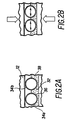
- FIG 2a shows a schematic of the tubes 34a and 34b in an unstressed state.
- the tubes shown in this figure are seated in the semi-circular seats 36 which are formed in an elastomeric material 38.
- On top of the tubes rests inner sole 12.
- the tubes may be completely encapsulated by the polyurethane material and in fact in a preferred embodiment of the invention the tubes are completely encapsulated, including encapsulation of the ends of the tubes. By encapsulating the ends of the tubes, the ends do not easily collapse as with open ended tubes.
- the inner sole 12 may be attached directly to the elastomeric material. In such a case there may be a space between the tubes 34a and 34b and the inner sole 12 which is filled with the elastomeric material.
- FIG. 2b of the accompanying drawings is a schematic of the tubes of the present invention under compression.
- the large arrows represent the force of a foot pressing on the midsole and the corresponding pressure from the ground.
- the tubes are compressed and are therefore no longer circular in cross-section.
- the tubes have a major axis which is parallel to the ground, the material between the tube is compressed. In other words, the smallest distance between the tubes is decreased thereby causing the elastomeric material between the tubes to compress.
- This compression in turn helps to resist further compression of the midsole.
- One aspect of the invention is that the tubes 34a and 34b never come into contact with each other. This avoids abrupt changes in the cushioning effect and creates a constant pressure gradient through the thickness of the midsole.
- the midsole After the forces shown in Figure 2b are removed, the midsole returns to the configuration shown in Figure 2a.
- the Hytrel used to practice the invention has good memory characteristics and therefore readily returns to the original configuration. Because the material between the tubes 32 has been compressed, a force is generated in the compressed material to help the tubes return to their original shape. Also, the pressure created by adjacent tube members generates a quicker response in returning the tubes to their original shape.
- the spacing of the tubes as well as the material used to make the tubes and the encapsulating midsole must be carefully chosen.
- the outside diameter of the tubes should be between 4 millimeters and 18 millimeters and must preferably allow for at least one millimeter of polyurethane encapsulation at the bottom of the tubes. If the entire tube is encapsulated there should be at least one millimeter of encapsulation at the top and bottom of the tubes.
- the wall thickness of the tubes should be between 0.4 millimeter and 1.0 millimeters and the spacing between the tubes should be between 0.5 millimeter and 9.0 millimeters.
- the above spacing is measured at the closest point between tubes and is measured in an unstressed configuration.
- the closest distance between the tubes shown in Figure 2a should be between 0.5 millimeter and 9.0 millimeters.
- the distance between the tubes is chosen as a function of the desired amount of tube collapse desired before the effects of the compression between the tubes has a significant effect.
- the tubes are harder than the surrounding material and preferably have a Shore D Durometer hardness of between 55 and 72.
- the surrounding elastomeric material may have a Asker C Durometer hardness of between 35 and 65 in the preferred embodiment of the invention.
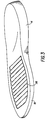
- Figure 3 shows one embodiment of the invention in which tubes 28 are placed in the forefoot portion 18 of a midsole 14.
- the tubes are placed in the forefoot portion 18 only and a solid polyurethane, EVA, or other elastomeric material is used to form the heel portion of the shoe.
- EVA Elastomeric material
- any conventional method may be used to form the heel while the present invention is used in the forefoot section.
- Figure 4 shows an embodiment of the invention wherein tubes 30 are placed only in the heel portion of midsole 14.
- a conventional forefoot section is used in combination with the invention.
- FIGS 5 and 6 show two possible methods of making the invention.
- the tubes of Hytrel and the polyurethane can be molded into the shape of a midsole as shown in Figure 5 or a die cutout may be formed into pieces and incorporated into another midsole component.
- the cutaway views of Figure 5 are for illustration only.
- the midsole is a single unitary piece which has had Hytrel or other hollow tubes encapsulated thereby.
- heel tubes 30 are encapsulated into a heel die cutout material formed of either polyurethane or ethylene vinyl acetate (EVA).
- EVA ethylene vinyl acetate
- the die cutout section 41 is placed within cutout 46 and attached in any conventional manner.
- the die cutout section 41 may be glued in place using any conventional bonding material.
- the heel die cut material 40 may be a different material than the material used to form the main part of the midsole 14.
- the heel die cutout material 40 may be formed of polyurethane while the remaining portion of midsole 14 may be formed with a material such as ethylene vinyl acetate.
- the forefoot portion of the midsole 18 may be formed by using a forefoot die cutout section which includes a forefoot die cutout material 43 and forefoot tubes 28.
- the die cutout section of the forefoot 42 may be inserted into opening 48 in the forefoot of the midsole. This is done in the same manner as with the heel as described above.
- Grooves 44 may be included in the forefoot section for the purposes of flexibility.
- the forefoot tubes 28 in Figure 6 are shown to extend perpendicular to the longitudinal axis of the midsole, in the preferred embodiment of the invention the forefoot tubes 28 are angled to run parallel with the metatarsal portion of the foot. Typically the tubes are angled approximately 13° from perpendicular to the longitudinal axis of the midsole such that the tubes are furthest away from the heel on the medial side of the shoe.
Landscapes
- Footwear And Its Accessory, Manufacturing Method And Apparatuses (AREA)
Applications Claiming Priority (2)
| Application Number | Priority Date | Filing Date | Title |
|---|---|---|---|
| US7021487A | 1987-07-06 | 1987-07-06 | |
| US70214 | 1987-07-06 |
Publications (2)
| Publication Number | Publication Date |
|---|---|
| EP0298449A2 true EP0298449A2 (fr) | 1989-01-11 |
| EP0298449A3 EP0298449A3 (fr) | 1989-08-23 |
Family
ID=22093896
Family Applications (1)
| Application Number | Title | Priority Date | Filing Date |
|---|---|---|---|
| EP88110786A Withdrawn EP0298449A3 (fr) | 1987-07-06 | 1988-07-06 | Eléments élastiques tubulaires pour chaussures |
Country Status (4)
| Country | Link |
|---|---|
| EP (1) | EP0298449A3 (fr) |
| JP (1) | JPS6486902A (fr) |
| KR (1) | KR890701037A (fr) |
| WO (1) | WO1989000017A1 (fr) |
Cited By (10)
| Publication number | Priority date | Publication date | Assignee | Title |
|---|---|---|---|---|
| US5155864A (en) * | 1991-04-23 | 1992-10-20 | Lisco, Inc. | Inflatable bladders for game gloves |
| US5155865A (en) * | 1991-04-23 | 1992-10-20 | Lisco, Inc. | Inflatable bladders for game gloves |
| US5155927A (en) * | 1991-02-20 | 1992-10-20 | Asics Corporation | Shoe comprising liquid cushioning element |
| US5423088A (en) * | 1991-04-23 | 1995-06-13 | Lisco, Inc. | Inflatable game gloves |
| WO1998025493A1 (fr) * | 1996-12-12 | 1998-06-18 | Etablissements Chupin Batardiere | Semelle a poche d'air, article chaussant muni d'une telle semelle et son procede de montage |
| US6701529B1 (en) | 1999-02-05 | 2004-03-09 | Extrude Hone Corporation | Smart padding system utilizing an energy absorbent medium and articles made therefrom |
| RU2348337C2 (ru) * | 2006-08-31 | 2009-03-10 | Ольга Владимировна Иванова | Способ принудительной вентиляции обуви |
| US9125453B2 (en) | 2010-05-28 | 2015-09-08 | K-Swiss Inc. | Shoe outsole having tubes |
| US20240225186A9 (en) * | 2022-10-19 | 2024-07-11 | Nike, Inc. | Article of footwear including a sole structure |
| WO2026018164A1 (fr) * | 2024-07-15 | 2026-01-22 | Reebok International Limited | Article chaussant avec système de retour d'énergie |
Families Citing this family (3)
| Publication number | Priority date | Publication date | Assignee | Title |
|---|---|---|---|---|
| DE4320833C1 (de) * | 1993-06-23 | 1994-09-22 | Roland Man Druckmasch | Verfahren und Vorrichtung zum Austausch eines Rakelblattes einer Kammerrakel für Rotationsdruckmaschinen |
| JP2012090657A (ja) * | 2010-10-25 | 2012-05-17 | Yoshimoto Kawauchi | 穴有り弾性部材、靴の衝撃吸収・反発ユニット、およびその穴有り弾性部材を複数中底に搭載した靴 |
| JP7474092B2 (ja) * | 2020-03-30 | 2024-04-24 | 美津濃株式会社 | シューズ用ソール構造体およびその製造方法、ならびに当該ソール構造体を備えたシューズ |
Family Cites Families (17)
| Publication number | Priority date | Publication date | Assignee | Title |
|---|---|---|---|---|
| FR958766A (fr) * | 1950-03-17 | |||
| US1498838A (en) * | 1923-03-16 | 1924-06-24 | Jr James Thomas Harrison | Pneumatic shoe |
| US1640302A (en) * | 1924-07-10 | 1927-08-23 | Charles Van Tassell | Shoe attachment |
| US1929126A (en) * | 1931-05-07 | 1933-10-03 | Tuki Ken | Resilient sole element for footwear |
| US2100492A (en) * | 1933-10-23 | 1937-11-30 | Converse Rubber Company | Pneumatic sheet material and method of making |
| FR1310482A (fr) * | 1961-01-12 | 1962-11-30 | Perfectionnements aux objets chaussants | |
| CH483807A (de) * | 1967-12-21 | 1970-01-15 | Madoery Oppliger Hermann | Pneumatisches Polster für Schuhe |
| US4235026A (en) * | 1978-09-13 | 1980-11-25 | Motion Analysis, Inc. | Elastomeric shoesole |
| JPS5599907A (en) * | 1979-01-27 | 1980-07-30 | Denki Kagaku Kogyo Kk | Copolymerization of chloroprene with unsaturated nitrile |
| DE3029258A1 (de) * | 1980-08-01 | 1982-04-01 | Adidas Sportschuhfabriken Adi Dassler Kg, 8522 Herzogenaurach | Sohle fuer sportschuhe, insbesondere zur verwendung auf harten bahnen und geraet zum einsetzen eines stuetzkoerpers in die sohle |
| AT371978B (de) * | 1979-02-07 | 1983-08-25 | Adidas Sportschuhe | Sohle fuer sportschuhe, insbesondere zur verwendung auf harten bahnen |
| US4271606A (en) * | 1979-10-15 | 1981-06-09 | Robert C. Bogert | Shoes with studded soles |
| FR2550424B1 (fr) * | 1983-08-10 | 1987-08-14 | Rudy M F | Chaussure de sport perfectionnee et dispositif de stabilisation elastique pour une chaussure de ce type |
| CH662484A5 (de) * | 1983-09-29 | 1987-10-15 | Bata Schuhe Ag | Modular aufgebaute tretunterlage. |
| DE3430845A1 (de) * | 1983-12-09 | 1985-07-04 | adidas Sportschuhfabriken Adi Dassler Stiftung & Co KG, 8522 Herzogenaurach | Laufsohle fuer schuhe, insbesondere sportschuhe mit einstellbarer fersendaempfung |
| US4656760A (en) * | 1985-02-26 | 1987-04-14 | Kangaroos U.S.A., Inc. | Cushioning and impact absorptive means for footwear |
| US4754559A (en) * | 1987-05-27 | 1988-07-05 | Cohen Elie | Shoe with midsole including deflection inhibiting inserts |
-
1988
- 1988-07-06 EP EP88110786A patent/EP0298449A3/fr not_active Withdrawn
- 1988-07-06 WO PCT/US1988/002280 patent/WO1989000017A1/fr not_active Ceased
- 1988-07-06 JP JP63168325A patent/JPS6486902A/ja active Pending
- 1988-07-06 KR KR1019890700402A patent/KR890701037A/ko not_active Withdrawn
Cited By (13)
| Publication number | Priority date | Publication date | Assignee | Title |
|---|---|---|---|---|
| US5155927A (en) * | 1991-02-20 | 1992-10-20 | Asics Corporation | Shoe comprising liquid cushioning element |
| US5493792A (en) * | 1991-02-20 | 1996-02-27 | Asics Corporation | Shoe comprising liquid cushioning element |
| US5155864A (en) * | 1991-04-23 | 1992-10-20 | Lisco, Inc. | Inflatable bladders for game gloves |
| US5155865A (en) * | 1991-04-23 | 1992-10-20 | Lisco, Inc. | Inflatable bladders for game gloves |
| US5423088A (en) * | 1991-04-23 | 1995-06-13 | Lisco, Inc. | Inflatable game gloves |
| FR2757025A1 (fr) * | 1996-12-12 | 1998-06-19 | Chupin Batardiere Ets | Perfectionnement aux articles chaussants |
| WO1998025493A1 (fr) * | 1996-12-12 | 1998-06-18 | Etablissements Chupin Batardiere | Semelle a poche d'air, article chaussant muni d'une telle semelle et son procede de montage |
| US6701529B1 (en) | 1999-02-05 | 2004-03-09 | Extrude Hone Corporation | Smart padding system utilizing an energy absorbent medium and articles made therefrom |
| RU2348337C2 (ru) * | 2006-08-31 | 2009-03-10 | Ольга Владимировна Иванова | Способ принудительной вентиляции обуви |
| US9125453B2 (en) | 2010-05-28 | 2015-09-08 | K-Swiss Inc. | Shoe outsole having tubes |
| US20240225186A9 (en) * | 2022-10-19 | 2024-07-11 | Nike, Inc. | Article of footwear including a sole structure |
| US12357057B2 (en) | 2022-10-19 | 2025-07-15 | Nike, Inc. | Article of footwear including a sole structure |
| WO2026018164A1 (fr) * | 2024-07-15 | 2026-01-22 | Reebok International Limited | Article chaussant avec système de retour d'énergie |
Also Published As
| Publication number | Publication date |
|---|---|
| JPS6486902A (en) | 1989-03-31 |
| WO1989000017A1 (fr) | 1989-01-12 |
| KR890701037A (ko) | 1989-12-19 |
| EP0298449A3 (fr) | 1989-08-23 |
Similar Documents
| Publication | Publication Date | Title |
|---|---|---|
| US5005300A (en) | Tubular cushioning system for shoes | |
| US5979078A (en) | Cushioning device for a footwear sole and method for making the same | |
| EP1916917B1 (fr) | Composant de semelle d'article chaussant dote d'une piece rapportee | |
| CN105101830B (zh) | 具有中央抗拉特征的鞋类流体填充室 | |
| US6192606B1 (en) | Helium filled sole | |
| US5014449A (en) | Shoe sole construction | |
| US7132032B2 (en) | Bladder with multi-stage regionalized cushioning | |
| US6402879B1 (en) | Method of making bladder with inverted edge seam | |
| EP1803365B1 (fr) | Semelle de chaussure dotée d'une seule cavité étanche | |
| EP0298449A2 (fr) | Eléments élastiques tubulaires pour chaussures | |
| EP2031994B1 (fr) | Article chaussant ou autre dispositif recevant un pied, muni d'une poche remplie de fluide et de structures de soutien et de renfort | |
| US5545463A (en) | Heel/metatarsal structure having premolded bulges | |
| AU736082B2 (en) | Shoe sole cushion | |
| US5679439A (en) | Heel/metatarsal structure having tapered stabilizing bulges | |
| CN101370405B (zh) | 具有带屈挠区的填充流体的腔的鞋类制品 | |
| US6374514B1 (en) | Footwear having a bladder with support members | |
| US5255451A (en) | Insert member for use in an athletic shoe | |
| WO1996016564A9 (fr) | Dispositif d'amortissement pour semelle de chaussure et procede de fabrication dudit dispositif | |
| CN1981662A (zh) | 用于鞋类的减震系统 | |
| CN102076235A (zh) | 改进的鞋底结构 | |
| EP0483145B1 (fr) | Element rapporte pour chaussures d'athletisme | |
| EP0629360B1 (fr) | Dispositif d'amortissement pour chaussures | |
| HK1106402A (en) | Cushioning system for footwear |
Legal Events
| Date | Code | Title | Description |
|---|---|---|---|
| PUAI | Public reference made under article 153(3) epc to a published international application that has entered the european phase |
Free format text: ORIGINAL CODE: 0009012 |
|
| AK | Designated contracting states |
Kind code of ref document: A2 Designated state(s): AT BE CH DE ES FR GB GR IT LI NL SE |
|
| PUAL | Search report despatched |
Free format text: ORIGINAL CODE: 0009013 |
|
| AK | Designated contracting states |
Kind code of ref document: A3 Designated state(s): AT BE CH DE ES FR GB GR IT LI NL SE |
|
| RHK1 | Main classification (correction) |
Ipc: A43B 13/18 |
|
| 17P | Request for examination filed |
Effective date: 19900222 |
|
| 17Q | First examination report despatched |
Effective date: 19910702 |
|
| STAA | Information on the status of an ep patent application or granted ep patent |
Free format text: STATUS: THE APPLICATION IS DEEMED TO BE WITHDRAWN |
|
| 18D | Application deemed to be withdrawn |
Effective date: 19920717 |