EP0299929A1 - Federnde Vorrichtung zur Verbindung von zwei Konstruktionselementen - Google Patents
Federnde Vorrichtung zur Verbindung von zwei Konstruktionselementen Download PDFInfo
- Publication number
- EP0299929A1 EP0299929A1 EP88830264A EP88830264A EP0299929A1 EP 0299929 A1 EP0299929 A1 EP 0299929A1 EP 88830264 A EP88830264 A EP 88830264A EP 88830264 A EP88830264 A EP 88830264A EP 0299929 A1 EP0299929 A1 EP 0299929A1
- Authority
- EP
- European Patent Office
- Prior art keywords
- rods
- discs
- resilient member
- structural elements
- apart
- Prior art date
- Legal status (The legal status is an assumption and is not a legal conclusion. Google has not performed a legal analysis and makes no representation as to the accuracy of the status listed.)
- Granted
Links
- 230000033001 locomotion Effects 0.000 claims abstract description 7
- 238000006243 chemical reaction Methods 0.000 claims description 4
- 229910052729 chemical element Inorganic materials 0.000 abstract 1
- 238000010521 absorption reaction Methods 0.000 description 1
- 230000006835 compression Effects 0.000 description 1
- 238000007906 compression Methods 0.000 description 1
Images

Classifications
-
- F—MECHANICAL ENGINEERING; LIGHTING; HEATING; WEAPONS; BLASTING
- F16—ENGINEERING ELEMENTS AND UNITS; GENERAL MEASURES FOR PRODUCING AND MAINTAINING EFFECTIVE FUNCTIONING OF MACHINES OR INSTALLATIONS; THERMAL INSULATION IN GENERAL
- F16F—SPRINGS; SHOCK-ABSORBERS; MEANS FOR DAMPING VIBRATION
- F16F1/00—Springs
- F16F1/02—Springs made of steel or other material having low internal friction; Wound, torsion, leaf, cup, ring or the like springs, the material of the spring not being relevant
- F16F1/04—Wound springs
- F16F1/12—Attachments or mountings
- F16F1/125—Attachments or mountings where the end coils of the spring engage an axial insert
-
- B—PERFORMING OPERATIONS; TRANSPORTING
- B60—VEHICLES IN GENERAL
- B60T—VEHICLE BRAKE CONTROL SYSTEMS OR PARTS THEREOF; BRAKE CONTROL SYSTEMS OR PARTS THEREOF, IN GENERAL; ARRANGEMENT OF BRAKING ELEMENTS ON VEHICLES IN GENERAL; PORTABLE DEVICES FOR PREVENTING UNWANTED MOVEMENT OF VEHICLES; VEHICLE MODIFICATIONS TO FACILITATE COOLING OF BRAKES
- B60T8/00—Arrangements for adjusting wheel-braking force to meet varying vehicular or ground-surface conditions, e.g. limiting or varying distribution of braking force
- B60T8/18—Arrangements for adjusting wheel-braking force to meet varying vehicular or ground-surface conditions, e.g. limiting or varying distribution of braking force responsive to vehicle weight or load, e.g. load distribution
- B60T8/1837—Arrangements for adjusting wheel-braking force to meet varying vehicular or ground-surface conditions, e.g. limiting or varying distribution of braking force responsive to vehicle weight or load, e.g. load distribution characterised by the load-detecting arrangements
-
- F—MECHANICAL ENGINEERING; LIGHTING; HEATING; WEAPONS; BLASTING
- F16—ENGINEERING ELEMENTS AND UNITS; GENERAL MEASURES FOR PRODUCING AND MAINTAINING EFFECTIVE FUNCTIONING OF MACHINES OR INSTALLATIONS; THERMAL INSULATION IN GENERAL
- F16C—SHAFTS; FLEXIBLE SHAFTS; ELEMENTS OR CRANKSHAFT MECHANISMS; ROTARY BODIES OTHER THAN GEARING ELEMENTS; BEARINGS
- F16C7/00—Connecting-rods or like links pivoted at both ends; Construction of connecting-rod heads
- F16C7/04—Connecting-rods or like links pivoted at both ends; Construction of connecting-rod heads with elastic intermediate part of fluid cushion
Definitions
- the present invention relates to a resilient device for connection between two structural elements, particularly (but not exclusively) for connecting the control shaft of a braking modulator or corrector to an axle of a motor vehicle.
- the invention relates to a resilient connecting device comprising: two rods which are each intended to be connected to one of the structural elements, in particular, to the shaft of a braking modulator and to an axle respectively, two discs, each associated with one of the rods, and at least one resilient member whose ends are connected to the discs so as to oppose the movement apart of the rods through the discs; the rods, the discs and the resilient member forming an assembly adapted to act as a rigid connection when the stresses applied to it are less than a predetermined threshold, and to deform resiliently when the stresses exceed the threshold, so as to limit the amount of stress transmitted between the structural elements.
- the discs are constituted by end heads of the rods and the resilient member is constituted by a very stiff helical spring whose ends are anchored to the discs.
- the object of the present invention is to produce a resilient connecting device of the type defined above, which is very stiff but which is nevertheless able to absorb stresses both in tension and in compression.
- a device of the above-specified type the main characteristic of which lies in the fact that the rods are mounted for axial sliding relative to the discs and are provided with respective first reaction means adapted to cause the discs to move apart when the rods move towards each other, and with respective second reaction means adapted to cause the discs to move apart when the rods move apart, so that the movement of the rods both towards and away from each other causes tensioning of the resilient member from its undeformed rest condition.
- the resilient member is also conveniently constituted by a helical spring whose ends are anchored to the discs: this spring can be made in such a way that its coils are close together in the undeformed rest condition, since both tensile stresses and compressive stresses of the device are translated into a tensioning action applied to this spring.
- a braking corrector or modulator device of known type is generally indicated 1 and is fixed to the body or suspended structure 2 of a motor vehicle.
- This device comprises, also in known manner, a control shaft 3 pivoted at 4 about an axis passing through the body of the braking corrector 1 and articulated at 6 to a resilient connecting device 10 which is in turn connected to the axle 5 (for example, the rear axle) of the motor vehicle.
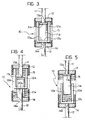
- a connecting device 10 comprises two aligned rods 11, 12 of which the first is connected to the control shaft 3 of the braking corrector and the second is connected to the axle 5 of the motor vehicle.
- these rods have prismatic sections and extend through central apertures 13a 14a and in discs 13 and 14. These discs have a series of lateral channels in which the end coils of a very stiff helical spring 15 are anchored.
- the end portions of the rods 11 and 12 are shaped like interpenetrating forks, with their prongs 11a and 12a facing downwardly and upwardly respectively.
- FIG 3 the connecting device according to the invention is shown in the rest condition.
- the yokes 11b and 12b face each other and are spaced apart and, moreover, the ends of the prongs of the forked portion of each rod and the yoke of the forked portion of the other rod press against the disc 13 and against the disc 14 respectively.
- the spring 15 is relieved.
- the spring 15 is preferably very stiff. Consequently, in use, the connecting device 10 as a whole behaves like a substantially rigid connecting element as long as the stresses applied to it are below a predetermined threshold. When the stresses exceed the threshold, however, it deforms resiliently in order to limit the amount of stress it transmits between the structural elements between which it is interposed and, in particular, in the example of Figure 1, to limit the stresses transmitted, for example, from the axle 5 to the control shaft 3 of the braking correcter.
- Figure 4 shows the deformed condition of the connecting element according to the invention when compressive forces are applied to the rods 11 and 12: the yokes 11b and 12b of the forked portions of the rods 11 and 12 move towards each other and, with their respective prongs 11a and 11b, cause the plates 13 and 14 to move away from each other, tensioning the spring 15 which extends.
- the connecting device according to the invention has considerable structural simplicity, as well as notable strength.
Landscapes
- Engineering & Computer Science (AREA)
- General Engineering & Computer Science (AREA)
- Mechanical Engineering (AREA)
- Transportation (AREA)
- Springs (AREA)
- Mutual Connection Of Rods And Tubes (AREA)
- Vibration Prevention Devices (AREA)
- Braking Systems And Boosters (AREA)
- Regulating Braking Force (AREA)
- Joining Of Building Structures In Genera (AREA)
Priority Applications (1)
| Application Number | Priority Date | Filing Date | Title |
|---|---|---|---|
| AT88830264T ATE69491T1 (de) | 1987-06-23 | 1988-06-21 | Federnde vorrichtung zur verbindung von zwei konstruktionselementen. |
Applications Claiming Priority (2)
| Application Number | Priority Date | Filing Date | Title |
|---|---|---|---|
| IT6754187 | 1987-06-23 | ||
| IT8767541A IT1210826B (it) | 1987-06-23 | 1987-06-23 | Dispositivo elastico di collegamento fra due elementi strutturali in particolare per il collegamento dell asta di comando di un modulatore di frenata ad un assale di un autoveicolo |
Publications (2)
| Publication Number | Publication Date |
|---|---|
| EP0299929A1 true EP0299929A1 (de) | 1989-01-18 |
| EP0299929B1 EP0299929B1 (de) | 1991-11-13 |
Family
ID=11303281
Family Applications (1)
| Application Number | Title | Priority Date | Filing Date |
|---|---|---|---|
| EP88830264A Expired - Lifetime EP0299929B1 (de) | 1987-06-23 | 1988-06-21 | Federnde Vorrichtung zur Verbindung von zwei Konstruktionselementen |
Country Status (6)
| Country | Link |
|---|---|
| US (1) | US4869473A (de) |
| EP (1) | EP0299929B1 (de) |
| AT (1) | ATE69491T1 (de) |
| DE (1) | DE3866177D1 (de) |
| ES (1) | ES2026690T3 (de) |
| IT (1) | IT1210826B (de) |
Cited By (3)
| Publication number | Priority date | Publication date | Assignee | Title |
|---|---|---|---|---|
| WO2003033322A1 (fr) * | 2001-10-17 | 2003-04-24 | Robert Bosch Gmbh | Dispositif de commande de frein de stationnement |
| FR2945982A1 (fr) * | 2009-05-27 | 2010-12-03 | Peugeot Citroen Automobiles Sa | Dispositif de butee de detente d'une suspension de vehicule |
| CN104876120A (zh) * | 2015-05-20 | 2015-09-02 | 芜湖市爱德运输机械有限公司 | 止挡装置和提升机 |
Families Citing this family (6)
| Publication number | Priority date | Publication date | Assignee | Title |
|---|---|---|---|---|
| US6098970A (en) * | 1997-09-22 | 2000-08-08 | Winston Lowe | Spring breakage safety system |
| US6789790B2 (en) * | 2002-06-18 | 2004-09-14 | Frank H. Speckhart | Helical coil spring damper assembly |
| US20100219572A1 (en) * | 2009-03-02 | 2010-09-02 | Gary Back | Independent Spring Cartridge |
| US9944144B2 (en) * | 2010-02-23 | 2018-04-17 | Renton Coil Spring Company | Spring and damper systems for attenuating the transmission of energy |
| US9360073B2 (en) | 2010-02-23 | 2016-06-07 | Renton Coil Spring Company | Tension spring mount with friction-resistant coating |
| US9689451B2 (en) * | 2010-02-23 | 2017-06-27 | Renton Coil Spring Co. | Tension spring mount |
Citations (5)
| Publication number | Priority date | Publication date | Assignee | Title |
|---|---|---|---|---|
| DE2524812A1 (de) * | 1974-06-04 | 1976-01-02 | Girling Ltd | Bremsregelventil-anordnung |
| US4385754A (en) * | 1981-03-16 | 1983-05-31 | General Motors Corporation | Spring-biased lost-motion link assembly |
| DE3235367A1 (de) * | 1982-09-24 | 1984-03-29 | Wabco Westinghouse Fahrzeugbremsen GmbH, 3000 Hannover | Federeinrichtung |
| FR2561338A1 (fr) * | 1984-03-13 | 1985-09-20 | Bennes Marrel | Dispositif sans frottement, pour le rappel par ressort d'une piece mobile en translation |
| GB2167506A (en) * | 1984-11-16 | 1986-05-29 | Teves Gmbh Alfred | Load-responsive brake pressure control unit |
Family Cites Families (6)
| Publication number | Priority date | Publication date | Assignee | Title |
|---|---|---|---|---|
| US1317788A (en) * | 1919-10-07 | Yielding tjjtit | ||
| US756175A (en) * | 1904-02-10 | 1904-03-29 | August F Meisselbach | Pocket-scale. |
| US1062312A (en) * | 1911-10-23 | 1913-05-20 | Cecil Watson | Buffing and draft gear for railway and other rolling-stock. |
| US1189963A (en) * | 1915-02-04 | 1916-07-04 | Charles W Jones | Yielding unit. |
| US1237758A (en) * | 1917-01-22 | 1917-08-21 | John F Courson | Draft-gear. |
| US4225123A (en) * | 1979-01-16 | 1980-09-30 | Hefren Fred W | Snubber assembly for motor homes |
-
1987
- 1987-06-23 IT IT8767541A patent/IT1210826B/it active
-
1988
- 1988-06-21 EP EP88830264A patent/EP0299929B1/de not_active Expired - Lifetime
- 1988-06-21 DE DE8888830264T patent/DE3866177D1/de not_active Expired - Fee Related
- 1988-06-21 ES ES198888830264T patent/ES2026690T3/es not_active Expired - Lifetime
- 1988-06-21 AT AT88830264T patent/ATE69491T1/de active
- 1988-06-23 US US07/210,481 patent/US4869473A/en not_active Expired - Fee Related
Patent Citations (5)
| Publication number | Priority date | Publication date | Assignee | Title |
|---|---|---|---|---|
| DE2524812A1 (de) * | 1974-06-04 | 1976-01-02 | Girling Ltd | Bremsregelventil-anordnung |
| US4385754A (en) * | 1981-03-16 | 1983-05-31 | General Motors Corporation | Spring-biased lost-motion link assembly |
| DE3235367A1 (de) * | 1982-09-24 | 1984-03-29 | Wabco Westinghouse Fahrzeugbremsen GmbH, 3000 Hannover | Federeinrichtung |
| FR2561338A1 (fr) * | 1984-03-13 | 1985-09-20 | Bennes Marrel | Dispositif sans frottement, pour le rappel par ressort d'une piece mobile en translation |
| GB2167506A (en) * | 1984-11-16 | 1986-05-29 | Teves Gmbh Alfred | Load-responsive brake pressure control unit |
Cited By (3)
| Publication number | Priority date | Publication date | Assignee | Title |
|---|---|---|---|---|
| WO2003033322A1 (fr) * | 2001-10-17 | 2003-04-24 | Robert Bosch Gmbh | Dispositif de commande de frein de stationnement |
| FR2945982A1 (fr) * | 2009-05-27 | 2010-12-03 | Peugeot Citroen Automobiles Sa | Dispositif de butee de detente d'une suspension de vehicule |
| CN104876120A (zh) * | 2015-05-20 | 2015-09-02 | 芜湖市爱德运输机械有限公司 | 止挡装置和提升机 |
Also Published As
| Publication number | Publication date |
|---|---|
| EP0299929B1 (de) | 1991-11-13 |
| ES2026690T3 (es) | 1992-05-01 |
| IT8767541A0 (it) | 1987-06-23 |
| ATE69491T1 (de) | 1991-11-15 |
| IT1210826B (it) | 1989-09-29 |
| DE3866177D1 (de) | 1991-12-19 |
| US4869473A (en) | 1989-09-26 |
Similar Documents
| Publication | Publication Date | Title |
|---|---|---|
| EP1237740B1 (de) | Führungslenker für fahrzeugaufhängungssystem | |
| US4869473A (en) | Resilient device for connection between two structural elements, particularly for connecting the control shaft of a braking modulator to an axle of a motor vehicle | |
| US3887045A (en) | Disc brake caliper assembly and method | |
| JPH05215204A (ja) | シフト・レバー機構用騒音振動減衰アセンブリ及びその形成方法 | |
| US4854562A (en) | Elastic mounting with rigidity blocked in one direction by the tension of a cable embedded in elastomer | |
| KR19990007051A (ko) | 적어도 두 개의 부품의 가요성 연결용 수단 | |
| US4192529A (en) | Stabilizer mounting means | |
| JPH0788219A (ja) | 締め具取付区域の両側に長さが変化する弾性伝達装置を備えた改良型スキー板 | |
| EP1513722B1 (de) | Haltevorrichtung mit dämpfer | |
| JPS5813767B2 (ja) | コイルばね用座 | |
| US20040089990A1 (en) | Single point attachment dual path suspension mount | |
| JPH08326829A (ja) | バンプストッパー | |
| GB2095366A (en) | Spring buffer | |
| GB2160616A (en) | Securing components to composite springs | |
| KR100243768B1 (ko) | 분할 압입형 스프링 부시 | |
| GB2289109A (en) | Spring/damper unit mounting arrangement | |
| US4828330A (en) | Brake corrector subject to the load of a vehicle | |
| US6024342A (en) | Suspension spring | |
| SU1232507A1 (ru) | Балансирна подвеска транспортного средства | |
| SU1120125A1 (ru) | Фрикционный амортизатор | |
| JPS595609Y2 (ja) | 車輪懸架装置のためのア−ム組立体 | |
| SU821270A1 (ru) | Амортизационно-центрирующее устрой-CTBO СцЕпКи шАХТНОй ВАгОНЕТКи | |
| US4466673A (en) | Hydraulic brake pressure control system of vehicle load responsive type | |
| JP2000145846A (ja) | ブレーキ緩衝装置 | |
| US20030227118A1 (en) | Single point attachment dual path suspension mount |
Legal Events
| Date | Code | Title | Description |
|---|---|---|---|
| PUAI | Public reference made under article 153(3) epc to a published international application that has entered the european phase |
Free format text: ORIGINAL CODE: 0009012 |
|
| AK | Designated contracting states |
Kind code of ref document: A1 Designated state(s): AT BE CH DE ES FR GB GR IT LI LU NL SE |
|
| 17P | Request for examination filed |
Effective date: 19890331 |
|
| 17Q | First examination report despatched |
Effective date: 19891109 |
|
| RAP1 | Party data changed (applicant data changed or rights of an application transferred) |
Owner name: BENDIX HEAVY VEHICLE SYSTEMS ITALIA S.P.A. |
|
| GRAA | (expected) grant |
Free format text: ORIGINAL CODE: 0009210 |
|
| AK | Designated contracting states |
Kind code of ref document: B1 Designated state(s): AT BE CH DE ES FR GB GR IT LI LU NL SE |
|
| PG25 | Lapsed in a contracting state [announced via postgrant information from national office to epo] |
Ref country code: NL Effective date: 19911113 Ref country code: LI Effective date: 19911113 Ref country code: GR Free format text: LAPSE BECAUSE OF FAILURE TO SUBMIT A TRANSLATION OF THE DESCRIPTION OR TO PAY THE FEE WITHIN THE PRESCRIBED TIME-LIMIT Effective date: 19911113 Ref country code: CH Effective date: 19911113 Ref country code: BE Effective date: 19911113 Ref country code: AT Effective date: 19911113 |
|
| REF | Corresponds to: |
Ref document number: 69491 Country of ref document: AT Date of ref document: 19911115 Kind code of ref document: T |
|
| ITF | It: translation for a ep patent filed | ||
| REF | Corresponds to: |
Ref document number: 3866177 Country of ref document: DE Date of ref document: 19911219 |
|
| ET | Fr: translation filed | ||
| REG | Reference to a national code |
Ref country code: CH Ref legal event code: PL |
|
| NLV1 | Nl: lapsed or annulled due to failure to fulfill the requirements of art. 29p and 29m of the patents act | ||
| REG | Reference to a national code |
Ref country code: ES Ref legal event code: FG2A Ref document number: 2026690 Country of ref document: ES Kind code of ref document: T3 |
|
| PGFP | Annual fee paid to national office [announced via postgrant information from national office to epo] |
Ref country code: GB Payment date: 19920515 Year of fee payment: 5 |
|
| PGFP | Annual fee paid to national office [announced via postgrant information from national office to epo] |
Ref country code: DE Payment date: 19920521 Year of fee payment: 5 |
|
| PGFP | Annual fee paid to national office [announced via postgrant information from national office to epo] |
Ref country code: SE Payment date: 19920526 Year of fee payment: 5 |
|
| PGFP | Annual fee paid to national office [announced via postgrant information from national office to epo] |
Ref country code: ES Payment date: 19920611 Year of fee payment: 5 |
|
| PG25 | Lapsed in a contracting state [announced via postgrant information from national office to epo] |
Ref country code: LU Free format text: LAPSE BECAUSE OF NON-PAYMENT OF DUE FEES Effective date: 19920630 |
|
| PGFP | Annual fee paid to national office [announced via postgrant information from national office to epo] |
Ref country code: FR Payment date: 19920630 Year of fee payment: 5 |
|
| PLBE | No opposition filed within time limit |
Free format text: ORIGINAL CODE: 0009261 |
|
| STAA | Information on the status of an ep patent application or granted ep patent |
Free format text: STATUS: NO OPPOSITION FILED WITHIN TIME LIMIT |
|
| 26N | No opposition filed | ||
| PG25 | Lapsed in a contracting state [announced via postgrant information from national office to epo] |
Ref country code: GB Effective date: 19930621 |
|
| PG25 | Lapsed in a contracting state [announced via postgrant information from national office to epo] |
Ref country code: SE Effective date: 19930622 Ref country code: ES Free format text: LAPSE BECAUSE OF EXPIRATION OF PROTECTION Effective date: 19930622 |
|
| GBPC | Gb: european patent ceased through non-payment of renewal fee |
Effective date: 19930621 |
|
| PG25 | Lapsed in a contracting state [announced via postgrant information from national office to epo] |
Ref country code: FR Effective date: 19940228 |
|
| PG25 | Lapsed in a contracting state [announced via postgrant information from national office to epo] |
Ref country code: DE Effective date: 19940301 |
|
| REG | Reference to a national code |
Ref country code: FR Ref legal event code: ST |
|
| EUG | Se: european patent has lapsed |
Ref document number: 88830264.3 Effective date: 19940110 |
|
| REG | Reference to a national code |
Ref country code: ES Ref legal event code: FD2A Effective date: 19990601 |
|
| PG25 | Lapsed in a contracting state [announced via postgrant information from national office to epo] |
Ref country code: IT Free format text: LAPSE BECAUSE OF NON-PAYMENT OF DUE FEES Effective date: 20050621 |