EP0300105A2 - Accélérateur d'ions électrostatique - Google Patents
Accélérateur d'ions électrostatique Download PDFInfo
- Publication number
- EP0300105A2 EP0300105A2 EP87307575A EP87307575A EP0300105A2 EP 0300105 A2 EP0300105 A2 EP 0300105A2 EP 87307575 A EP87307575 A EP 87307575A EP 87307575 A EP87307575 A EP 87307575A EP 0300105 A2 EP0300105 A2 EP 0300105A2
- Authority
- EP
- European Patent Office
- Prior art keywords
- ion
- power supply
- accelerating
- accelerator
- terminal
- Prior art date
- Legal status (The legal status is an assumption and is not a legal conclusion. Google has not performed a legal analysis and makes no representation as to the accuracy of the status listed.)
- Ceased
Links
Images


Classifications
-
- G—PHYSICS
- G21—NUCLEAR PHYSICS; NUCLEAR ENGINEERING
- G21K—HANDLING OF PARTICLES OR IONISING RADIATION NOT OTHERWISE PROVIDED FOR; IRRADIATION DEVICES; GAMMA RAY OR X-RAY MICROSCOPES
- G21K1/00—Arrangements for handling particles or ionising radiation, e.g. focusing or moderating
- G21K1/14—Arrangements for handling particles or ionising radiation, e.g. focusing or moderating using charge exchange devices, e.g. for neutralising or changing the sign of the electrical charges of beams
-
- A—HUMAN NECESSITIES
- A61—MEDICAL OR VETERINARY SCIENCE; HYGIENE
- A61N—ELECTROTHERAPY; MAGNETOTHERAPY; RADIATION THERAPY; ULTRASOUND THERAPY
- A61N5/00—Radiation therapy
- A61N5/10—X-ray therapy; Gamma-ray therapy; Particle-irradiation therapy
-
- H—ELECTRICITY
- H05—ELECTRIC TECHNIQUES NOT OTHERWISE PROVIDED FOR
- H05H—PLASMA TECHNIQUE; PRODUCTION OF ACCELERATED ELECTRICALLY-CHARGED PARTICLES OR OF NEUTRONS; PRODUCTION OR ACCELERATION OF NEUTRAL MOLECULAR OR ATOMIC BEAMS
- H05H5/00—Direct voltage accelerators; Accelerators using single pulses
-
- H—ELECTRICITY
- H05—ELECTRIC TECHNIQUES NOT OTHERWISE PROVIDED FOR
- H05H—PLASMA TECHNIQUE; PRODUCTION OF ACCELERATED ELECTRICALLY-CHARGED PARTICLES OR OF NEUTRONS; PRODUCTION OR ACCELERATION OF NEUTRAL MOLECULAR OR ATOMIC BEAMS
- H05H5/00—Direct voltage accelerators; Accelerators using single pulses
- H05H5/06—Multistage accelerators
-
- A—HUMAN NECESSITIES
- A61—MEDICAL OR VETERINARY SCIENCE; HYGIENE
- A61N—ELECTROTHERAPY; MAGNETOTHERAPY; RADIATION THERAPY; ULTRASOUND THERAPY
- A61N5/00—Radiation therapy
- A61N5/10—X-ray therapy; Gamma-ray therapy; Particle-irradiation therapy
- A61N2005/1085—X-ray therapy; Gamma-ray therapy; Particle-irradiation therapy characterised by the type of particles applied to the patient
- A61N2005/1087—Ions; Protons
Definitions
- This invention relates to ion accelerators and, in particular, to ion accelerators useful for generating clinically significant quantities of medical isotopes useful in applications such as positron emission tomography.
- PET Positron Emission Tomography
- PETT Positron Emission Transaxial Tomography
- an array of sensors detects gamma rays emitted from tissues after the subject has been administered a natural biochemical substance (for example, gases, glucose or fatty acids) into which positron-emitting radio-isotopes have been incorporated.
- a computer calculates the paths of the gamma rays (which result from collisions of positrons and electrons) and interprets the data to generate a tomographic image.
- the resultant tomogram represents local concentrations of the isotope-containing substance in the tissues.
- the short-lived radio-isotopes are administered by intravenous injection or by having the subject inhale a gas containing small quantities of the radio-isotope.
- Isotopes which are often incorporated into such gases or injections are carbon-11, nitrogen-13, oxygen-15 and fluorine-18.
- these radio-isotopes are derived from boron, carbon, nitrogen and neon targets, respectively, by bombarding the targets with high-energy (approximately 6-15 MV) protons or deuterons obtained from a particle accelerator.
- the accelerator which is used to produce the isotope-generating particles is a cyclotron accelerator.
- cyclotron accelerators have significant drawbacks. Due to the short half-lives of the isotopes (ranging from approximately 2 minutes for oxygen-15 to 110 minutes for fluorine-18), the accelerator must be physically located in the medical center within a short distance from the PET scanning apparatus. At present, cyclotron accelerators suitable for use in a medical environment are expensive (on the order of 1-2 million dollars); large and heavy (15 to 20 tons) and require a trained staff to operate and maintain the apparatus.
- the high-energy ions produced by the cyclotron accelerator are generally used to bombard gas targets to obtain the isotopes.
- Gas targets must be separated from the high vacuum of the accelerator by a metallic-foil window. Because the ion beam has high energy, the window is rapidly destroyed, thus increasing the costs of maintenance and requiring highly trained operators who must disassemble the device to replace the window.
- an ion accelerator which can generate sufficient ion current in a low energy range for the production of clinically significant quantities of medical isotopes such as PET isotopes.
- Another object of this invention is to provide an ion accelerator which can deliver higher currents than conventional low energy accelerators.
- the accelerator is capable of producing up to a 4MV deuteron or proton beam with a minimum delivered beam current of approximately 200 microamperes.
- the accelerator may be capable of delivering currents of up to approximately 2 mA, as required by the application.
- solid state power supply shall mean a power supply utilizing discrete and/or integrated electronic components such as diodes or other rectifiers, transistors, resistors, capacitors or the like, at least some of which are solid state components.
- a solid state power supply is to be distinguished from an electromechanical power supply such as a Van de Graff power supply.
- the solid state power supply is a cascade rectifier high-voltage supply which utilizes a plurality of voltage multiplier stages driven by a high-frequency driver circuit to accelerate negatively-charged ions (produced by a high current negative-ion source) in a high-vacuum acceleration column.
- the power supply is preferably coaxial with the acceleration column and is designed to have a voltage gradient which substantially matches the maximum voltage gradient of the accelerator.
- the accelerated ions are projected through a foil-less window into a stripping cell located within the high-voltage terminal.
- the stripping cell comprises a field-free region in which two electrons are removed from each ion, thus converting the negative ions into positively-charged ions which are then accelerated through a second, high-vacuum accelerating column to a ground-potential target.
- the stripping cell may comprise a vacuum chamber containing a water vapor jet or a gas stripping cell. High vacuum is maintained in the accelerator columns by means of cryo-pumping of the water vapor in the high voltage terminal or by differential pumping.
- the inventive electrostatic accelerator is simpler to operate, more reliable and requires far less capital outlay than that required for a conventional medical cyclotron facility. Accordingly, such an accelerator will remove a major obstacle to the widespread acceptance of PET as a diagnostic tool, thereby opening up a considerably broader market for this technology.
- the inventive accelerator is capable of delivering ion beam currents of up to at least two milliamperes at energies of 2.2-4 MV. This is due to a number of factors as will be discussed hereinafter, including the high current capability of the solid state power supply. These factors, therefore, significantly increase the operating range of the accelerator as compared with another common tandem configuration, such as the tandem Van de Graff.
- a Van de Graff power supply is typically restricted to currents of under 200 microamperes which is insufficient for PET applications.
- the inventive accelerator may also be used in another medical application, that of producing epithermal neutrons for the destruction of tumor cells.
- epithermal neutrons would be produced by bombarding a lithium target with a 2.5 MV, 1 mA proton beam from the inventive accelerator.
- Compact, lightweight accelerators capable of delivering proton beams with these parameters are currently not available.
- Nitrogen-14 is bombarded with deuterons and releases a neutron becoming oxygen-15.
- carbon-11 would be obtained by bombarding a target formed of a boron containing substance such as one containing boron-10, nitrogen-11 would be obtained from a target of a carbon containing substance such as one containing carbon-12, oxygen-15 would be obtained from a target of a nitrogen containing substance such as one containing nitrogen-14 and fluorine-18 would be obtained for a target of a neon containing substance such as one containing neon-20.
- the deuteron reactions listed in Table I are characterized by their low threshold energies (typically under 1 MV) and by cross-sections which peak at low incident energies (typically below 3 MV).
- the threshold energy is the lowest energy at which the reaction will take place and the maximum cross section energy is the incident deuteron energy which has the highest probability of reacting with the target nucleus.
- Table I indicates that low energy deuterons may be used to produce the relevant isotopes.
- the production of Oxygen-15 is chosen as an example because of its clinical importance in PET technology. However, the conclusions and techniques disclosed below are also applicable to the production of carbon-11, nitrogen-13 and fluorine-18.
- the inventive ion accelerator may be used with solid targets, thus eliminating the requirement of a metallic foil window to separate the accelerator vacuum from the target gas.
- a yield of at least .2 Ci of oxygen-15 must be obtained.
- the oxygen-15 yield at saturation in a lithium-nitride target is plotted as a function as incident deuteron energy in Figure 1.
- the curve in Figure 1 is a theoretical curve which can be calculated from published cross sections for the nitrogen-14/oxygen-15 reaction and from known stopping powers for ions in materials.
- Figure 1 shows that from 1-10 mCi/ ⁇ A of oxygen-15 can be obtained with an incident energy of 2.2-4.0 MV, respectively.
- oxygen-15 activity can be produced at a deuteron energy of 2.2 MV.
- oxygen-15 yields exceeding those which may be obtained with medical cyclotrons may be produced by the inventive accelerator.
- the fluorine-18 yield is about a factor of ten lower than the oxygen-15 yield. Therefore, currents in the range of 1-2 mA will be required for fluorine-18 production.
- the beam parameters required by the reactions illustrated in Figure 1 to obtain significant quantities of oxygen-15, carbon-11 and fluorine-18 may be obtained by using the electrostatic accelerator shown in schematic form in Figure 2 to accelerate deuterons to the required energy.
- Negative-ion source 200 may be a magnetically filtered volume production negative-ion source.
- the construction and operation of such a negative-ion source is discussed in "Extraction of H- Beams from a Magnetically-Filtered Multi-cusp Source", R.L. York, R.R. Stevens, Jr., K.N. Leung and K.W. Ehlers, Review of Scientific Instruments , Volume 55, pg. 681 (1984); "The Development of a High-current H- Injector for the Proton Storage Ring at LAMPF", R.L. York, R.R.
- the negative-ion beam 202 is injected at low energy into accelerating column 208 which is maintained at high vacuum by means of vacuum pumps attached to tee fitting 201.
- the beam is attracted to and accelerated by voltage supplied to high-voltage terminal 210.
- the voltage is created and maintained by means of cascade rectifier circuit 206 connected between source 200 and voltage terminal 210.
- the ion beam attains an energy of qV t where V t is the potential of the high-voltage terminal with respect to ground and q is the charge of the negative ion.
- a stripping cell 212 is located in terminal 210 and converts the negative-ion beam into a positive-ion beam with high efficiency.
- the stripping cell which consists of a foil-less, field-free cell, may, for example, be a conventional gas stripping cell, but is preferably a water jet stripping cell.
- the construction and operation of the gas stripping cell is well known while the construction and operation of a water jet stripping cell is described in "Water Vapor Jet Target for the Charge Changing of Fast Ion Beams", M. Roos, P.H. Rose, A.B. Wittkower, N.B. Brooks, and R.P. Bastide, Review of Scientific Instruments , Volume 36, Number 4 (April 1965).
- N2 nitrogen
- the water vapor jet stripper can provide conversion efficiencies of greater than 90%.
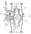
- Fig. 4 shows a cross section of a water vapor jet stripper 400 suitable for use in the ion accelerator shown in Fig. 2.
- water in reservoir or boiler 402 is heated by freon gas flowing through heating tubes 404 immersed in the water.
- the heated water forms water vapor, the pressure of which is a function of the water temperature.
- the water vapor passes through a needle valve which is controlled by control 406, reaching sonic velocity as it passes through the valve, and then expands in expansion chamber 408.
- the temperature and pressure of the vapor are reduced on passing through the needle valve, but the vapor is reheated in the expansion chamber, the walls of which are at the temperature of boiler 402.
- the vapor temperature returns very nearly to the original temperature, but at greatly reduced pressure.
- the heated water vapor passes through a sonic nozzle 410.
- the resulting water vapor jet 412 produced by the sonic nozzle is confined to an approximately 60° expansion angle because of its high speed flow (in the order of Mach 1).
- the water vapor is collected by a condenser 413, the walls of which are maintained at a temperature of approximately -164° C by liquid nitrogen in contact with the condenser walls, the liquid nitrogen being provided through tube 414 to reservoir 416 and the heated nitrogen gas being exhausted through tube 418.
- the positive-ion beam 218 is accelerated through accelerator column 216 to the target (not shown) which is preferably maintained at ground potential.
- High vacuum is maintained between stripping cell 212 and accelerator columns 208 and 216 by cyro-pumping in the terminal stripper or by other standard, suitable means.
- the entire apparatus is sealed in a pressure chamber 222 which is filled with a high pressure insulating gas 204 for example, sulphur hexafluoride (SF6).
- a high pressure insulating gas 204 for example, sulphur hexafluoride (SF6).
- SF6 sulphur hexafluoride
- conventional high-voltage grading rings 214 are provided in order to evenly spread the high-voltage potential across the accelerating column.
- FIG. 3 is a schematic diagram of the cascade rectifier circuit which may be used to generate the accelerating potential.
- the cascade rectifier circuit consists of a number of identical stages 300 each of which consists of four diodes, 302-308 and a capacitor 310. The stages are coupled by additional capacitors 312 and 314.
- the high-voltage terminal 320, of this circuit attains a voltage of 2NV p under no load conditions where N is the number of multiplier stages and V p is the peak center voltage of the high-frequency driver circuit 350.
- I load current
- the output voltage, 2NV p drops by an amount given by: (where f is the frequency of the driver and C is the capacitance per stage) and exhibits a voltage ripple of:
- the illustrative accelerator may be desired to generate a 3.8 MV deuteron beam with a current of 1 mA.
- This bean will produce an oxygen-15 activity level of approximately 10 Ci of oxygen-15 or 1 Ci of fluorine-18.
- a 1.9 MV high-voltage potential must be produced by the cascade rectifier circuit.
- a capacitance of 0.006 uf per stage is chosen with a driver frequency of 40 KiloHertz. With these parameters, each stage produces a 50 kV potential and, thus, 40 stages are needed to generate the 1.9 MV terminal potential when voltage droop is taken into account.
- the tandem configuration requires that the power supply deliver twice the final beam current and thus for a delivered beam current of 1 milliampere, the current, I, in equations (1) and (2) is 2 milliamperes.
- the capacitance and frequency parameters discussed above yield a loaded output voltage droop and ripple given by equations (1) and (2) of 92 kilovolts and 208 volts, respectively.
- the illustrative 40-stage cascade rectifier circuit produces an actual terminal voltage of 1.91 MV and a beam energy of 3.82 MV for a delivered beam current of 1 milliampere.
- the length of the cascade rectifier 206 and thus of accelerator column 208 is dictated by the physical size of the capacitors.
- Capacitors with values suitable for use with the preceding illustrative power supply are commerically available from High Energy Corporation, located at Lower Valley Road, Parkersburg, PA, and are cylindrically packaged with a diameter of 2.5 inches and a length of 1.0 inch.
- the resulting 3.8 MV accelerator would require a negative-ion accelerating column of approximately 1.0 meter in length to accommodate the capacitors.
- the power supply electric field gradient will be 19.7 kv/cm which will match the maximum voltage gradient of the accelerating column. This permits optimum acceleration of the ion beam in chamber 206 while minimizing the overall size of the system through use of the coaxial configuration.
- a similar length would be used for the positive-ion accelerator column.
- the accelerator would have an overall length of approximately 2.5 meters (including the stripping cell) and a diameter (dictated by high-voltage standoff requirements) of approximately 1 meter.
- the inventive accelerator can be used with solid targets to avoid the use of a metallic foil window at the beam output. Such windows require frequent maintenance due to damage by the deuteron beam.
- a solid target bombarded by accelerated deuterons can be used to generate oxygen-15 or other isotopes.
- the oxygen-15 can be released from the solid target by means of a number of conventional techniques including dissolving the target in a suitable solvent.
- tandem accelerator has been illustrated as the means for producing the high current, low energy ion beam for producing medical isotopes, and such a tandem accelerator is clearly superior in terms of size, cost, complexity, and ease of use and maintenance to any other ion accelerator currently known for producing such isotopes with a high current, low energy ion beam, it is within the contemplation of the invention to produce such isotopes using any suitable low energy, high current ion source.
- An example of an ion source capable of providing the required currents at low energy levels, although at much higher cost, and with a much larger and more complex piece of equipment, is a radio-frequency quadrupole (RFQ) accelerator of the type described in "Four-Rod- /2-RFQ for Light Ion Acceleration", A. Schempp, H. Deitinghoff, M. Ferch, P. Junior and H. Klein, Accelerator Technology , Volume VIII, pg. 831 (1985).
- RFQ radio-frequency quadrupole
Landscapes
- Engineering & Computer Science (AREA)
- Physics & Mathematics (AREA)
- Health & Medical Sciences (AREA)
- Spectroscopy & Molecular Physics (AREA)
- Plasma & Fusion (AREA)
- Biomedical Technology (AREA)
- Pathology (AREA)
- High Energy & Nuclear Physics (AREA)
- General Engineering & Computer Science (AREA)
- Nuclear Medicine, Radiotherapy & Molecular Imaging (AREA)
- Radiology & Medical Imaging (AREA)
- Life Sciences & Earth Sciences (AREA)
- Animal Behavior & Ethology (AREA)
- General Health & Medical Sciences (AREA)
- Public Health (AREA)
- Veterinary Medicine (AREA)
- Particle Accelerators (AREA)
- Electron Sources, Ion Sources (AREA)
Applications Claiming Priority (2)
| Application Number | Priority Date | Filing Date | Title |
|---|---|---|---|
| US72883 | 1987-07-20 | ||
| US07/072,883 US4812775A (en) | 1986-04-30 | 1987-07-20 | Electrostatic ion accelerator |
Publications (2)
| Publication Number | Publication Date |
|---|---|
| EP0300105A2 true EP0300105A2 (fr) | 1989-01-25 |
| EP0300105A3 EP0300105A3 (fr) | 1989-08-09 |
Family
ID=22110316
Family Applications (1)
| Application Number | Title | Priority Date | Filing Date |
|---|---|---|---|
| EP87307575A Ceased EP0300105A3 (fr) | 1987-07-20 | 1987-08-27 | Accélérateur d'ions électrostatique |
Country Status (3)
| Country | Link |
|---|---|
| US (1) | US4812775A (fr) |
| EP (1) | EP0300105A3 (fr) |
| JP (1) | JPS6435898A (fr) |
Cited By (3)
| Publication number | Priority date | Publication date | Assignee | Title |
|---|---|---|---|---|
| US7498588B1 (en) | 2008-05-07 | 2009-03-03 | International Business Machines Corporation | Tandem accelerator having low-energy static voltage injection and method of operation thereof |
| WO2011077082A1 (fr) * | 2009-12-21 | 2011-06-30 | The Science And Technology Facilities Council | Générateur de particules chargées |
| CN102348321A (zh) * | 2011-10-01 | 2012-02-08 | 中国科学院近代物理研究所 | 薄壁真空管道及由薄壁真空管道制造真空室的制造方法 |
Families Citing this family (27)
| Publication number | Priority date | Publication date | Assignee | Title |
|---|---|---|---|---|
| US5124658A (en) * | 1988-06-13 | 1992-06-23 | Adler Richard J | Nested high voltage generator/particle accelerator |
| US5037602A (en) * | 1989-03-14 | 1991-08-06 | Science Applications International Corporation | Radioisotope production facility for use with positron emission tomography |
| US5135704A (en) * | 1990-03-02 | 1992-08-04 | Science Research Laboratory, Inc. | Radiation source utilizing a unique accelerator and apparatus for the use thereof |
| US5235239A (en) * | 1990-04-17 | 1993-08-10 | Science Research Laboratory, Inc. | Window construction for a particle accelerator |
| CA2055297C (fr) * | 1990-11-13 | 1996-10-08 | Iwao Kanno | Appareillage et methode de production et d'injection automatique de h--o |
| JP2839730B2 (ja) * | 1991-02-25 | 1998-12-16 | 株式会社東芝 | エミュレーション装置及び半導体装置 |
| GB2253738B (en) * | 1991-03-13 | 1995-06-07 | Atomic Energy Authority Uk | Tandem accelerator |
| US5189302A (en) * | 1991-10-28 | 1993-02-23 | The United States Of America As Represented By The United States Department Of Energy | Small system for tritium accelerator mass spectrometry |
| US5300891A (en) * | 1992-05-01 | 1994-04-05 | Genus, Inc. | Ion accelerator |
| JP2847601B2 (ja) * | 1992-10-27 | 1999-01-20 | 住友重機械工業株式会社 | 低速陽電子ビーム発生装置 |
| US6414327B1 (en) * | 1998-09-14 | 2002-07-02 | Newton Scientific, Inc. | Method and apparatus for ion beam generation |
| US7888891B2 (en) * | 2004-03-29 | 2011-02-15 | National Cerebral And Cardiovascular Center | Particle beam accelerator |
| JP4714884B2 (ja) * | 2004-03-29 | 2011-06-29 | 独立行政法人国立循環器病研究センター | 粒子線加速器 |
| JP2006286302A (ja) * | 2005-03-31 | 2006-10-19 | Ulvac Japan Ltd | 電圧発生ユニット、電圧発生装置及びこれを備えた荷電粒子加速器 |
| US7431526B2 (en) * | 2005-04-04 | 2008-10-07 | Taiwan Mindcatcher, Inc. | Pen with paper roll |
| JP4537924B2 (ja) * | 2005-09-29 | 2010-09-08 | 株式会社日立製作所 | 加速器利用システム |
| DE102005061560A1 (de) * | 2005-12-22 | 2007-07-05 | Siemens Ag | Verfahren zur Herstellung von radioaktiven Isotopen für die Positronen-Emissions-Tomographie |
| US20070242790A1 (en) * | 2006-03-30 | 2007-10-18 | The Regents Of The University Of California | 10B(d,n)11C REACTION BASED NEUTRON GENERATOR |
| JP4274379B2 (ja) * | 2006-05-12 | 2009-06-03 | 東京ニュークリア・サービス株式会社 | ホウ素中性子捕獲療法用ターゲットの製造方法 |
| JP5700536B2 (ja) * | 2011-03-04 | 2015-04-15 | 大学共同利用機関法人 高エネルギー加速器研究機構 | 複合型ターゲット |
| JP5697021B2 (ja) * | 2010-11-29 | 2015-04-08 | 大学共同利用機関法人 高エネルギー加速器研究機構 | 複合型ターゲット、複合型ターゲットを用いる中性子発生方法、及び複合型ターゲットを用いる中性子発生装置 |
| US20130279638A1 (en) * | 2010-11-29 | 2013-10-24 | Inter-University Research Insitute Corporation High Energy Accelerator Research | Composite type target, neutron generating method in use thereof and neutron generating apparatus in use thereof |
| GB2489400A (en) * | 2011-03-21 | 2012-10-03 | Siemens Ag | A compact epithermal neutron generator |
| US9591740B2 (en) | 2013-03-08 | 2017-03-07 | Tri Alpha Energy, Inc. | Negative ion-based neutral beam injector |
| CA2911525A1 (fr) | 2013-05-17 | 2014-11-20 | Martin A. Stuart | Accelerateur de paroi dielectrique utilisant du diamant ou du carbone de type diamant |
| US11678430B2 (en) * | 2019-08-30 | 2023-06-13 | Tae Technologies, Inc. | Neutron generating target for neutron beam systems |
| US12154750B2 (en) | 2020-06-25 | 2024-11-26 | Tae Technologies, Inc. | Systems, devices, and methods for ion beam modulation |
Family Cites Families (5)
| Publication number | Priority date | Publication date | Assignee | Title |
|---|---|---|---|---|
| DE1249418B (fr) * | 1961-07-17 | |||
| US4160905A (en) * | 1976-11-27 | 1979-07-10 | Kratos Limited | Electron microscopes |
| DE2738405A1 (de) * | 1977-08-25 | 1979-03-01 | Siemens Ag | Tandemionenbeschleuniger mit materiefreiem ionenumladebereich |
| FR2500949B1 (fr) * | 1981-03-02 | 1986-06-20 | Commissariat Energie Atomique | Generateur de neutrons de grande energie et application a la neutronotherapie |
| JPS5917500B2 (ja) * | 1981-03-18 | 1984-04-21 | 株式会社東芝 | 中性粒子検出装置 |
-
1987
- 1987-07-20 US US07/072,883 patent/US4812775A/en not_active Ceased
- 1987-08-27 EP EP87307575A patent/EP0300105A3/fr not_active Ceased
- 1987-09-30 JP JP62247749A patent/JPS6435898A/ja active Pending
Cited By (3)
| Publication number | Priority date | Publication date | Assignee | Title |
|---|---|---|---|---|
| US7498588B1 (en) | 2008-05-07 | 2009-03-03 | International Business Machines Corporation | Tandem accelerator having low-energy static voltage injection and method of operation thereof |
| WO2011077082A1 (fr) * | 2009-12-21 | 2011-06-30 | The Science And Technology Facilities Council | Générateur de particules chargées |
| CN102348321A (zh) * | 2011-10-01 | 2012-02-08 | 中国科学院近代物理研究所 | 薄壁真空管道及由薄壁真空管道制造真空室的制造方法 |
Also Published As
| Publication number | Publication date |
|---|---|
| US4812775A (en) | 1989-03-14 |
| EP0300105A3 (fr) | 1989-08-09 |
| JPS6435898A (en) | 1989-02-06 |
Similar Documents
| Publication | Publication Date | Title |
|---|---|---|
| US4812775A (en) | Electrostatic ion accelerator | |
| US5037602A (en) | Radioisotope production facility for use with positron emission tomography | |
| USRE34575E (en) | Electrostatic ion accelerator | |
| US5073913A (en) | Apparatus for acceleration and application of negative ions and electrons | |
| Waites et al. | What is the potential impact of the IsoDAR cyclotron on radioisotope production: a review | |
| Alfassi et al. | Elemental analysis by particle accelerators | |
| Nešković et al. | Status report of the VINCY Cyclotron | |
| US6753662B1 (en) | Intense and compact THz radiation source | |
| Alonso | High energy heavy ions: techniques and applications | |
| Jongen | Review of compact commercial accelerator products and applications | |
| Dubinov et al. | Recirculating electron accelerators with noncircular electron orbits as radiation sources for applications (a Review) | |
| Ghiorso et al. | The Omnitron: A Versatile Medium-Energy Synchrotron for the Acceleration of Light and Heavy Ions | |
| Crebbin et al. | First Phase of Heavy Ion Acceleration at the Bevatron | |
| Lebrun | Particle accelerators, instruments of discovery in physics | |
| Livingston | The Acceleration of Heavy Ions | |
| Laxdal et al. | Radioactive Ion Beams and Radiopharmaceuticals | |
| Thomas | High energy heavy ions | |
| Hamm | Multipurpose neutron generators based on the radio frequency quadrupole linear accelerator | |
| Barbalat | Technology and industrial spin-off from particle accelerators | |
| Lennox | Overview of accelerators in medicine | |
| Shefer et al. | High-current electrostatic accelerator for boron neutron capture therapy | |
| Hamm | Commercial applications of linacs | |
| Swenson | The Los Alamos Meson Physics Facility | |
| Hamm | Neutron production with compact ion linacs | |
| Waites et al. | What is the potential impact of the IsoDAR cyclotron on radioisotope production |
Legal Events
| Date | Code | Title | Description |
|---|---|---|---|
| PUAI | Public reference made under article 153(3) epc to a published international application that has entered the european phase |
Free format text: ORIGINAL CODE: 0009012 |
|
| AK | Designated contracting states |
Kind code of ref document: A2 Designated state(s): AT BE CH DE ES FR GB GR IT LI LU NL SE |
|
| PUAL | Search report despatched |
Free format text: ORIGINAL CODE: 0009013 |
|
| AK | Designated contracting states |
Kind code of ref document: A3 Designated state(s): AT BE CH DE ES FR GB GR IT LI LU NL SE |
|
| 17P | Request for examination filed |
Effective date: 19900209 |
|
| 17Q | First examination report despatched |
Effective date: 19920327 |
|
| STAA | Information on the status of an ep patent application or granted ep patent |
Free format text: STATUS: THE APPLICATION HAS BEEN REFUSED |
|
| 18R | Application refused |
Effective date: 19960114 |
|
| RIN1 | Information on inventor provided before grant (corrected) |
Inventor name: KLINKOWSTEIN,ROBERT EDWARD Inventor name: SHEFER, RUTH |