EP0300122B1 - Dispositif de transfert à fonctionnement discontinu permettant le passage transversal, pour système de transport - Google Patents
Dispositif de transfert à fonctionnement discontinu permettant le passage transversal, pour système de transport Download PDFInfo
- Publication number
- EP0300122B1 EP0300122B1 EP19880102870 EP88102870A EP0300122B1 EP 0300122 B1 EP0300122 B1 EP 0300122B1 EP 19880102870 EP19880102870 EP 19880102870 EP 88102870 A EP88102870 A EP 88102870A EP 0300122 B1 EP0300122 B1 EP 0300122B1
- Authority
- EP
- European Patent Office
- Prior art keywords
- right angle
- jump transfer
- angle jump
- transfer
- strips
- Prior art date
- Legal status (The legal status is an assumption and is not a legal conclusion. Google has not performed a legal analysis and makes no representation as to the accuracy of the status listed.)
- Expired
Links
- 239000000314 lubricant Substances 0.000 claims 2
- 230000003213 activating effect Effects 0.000 claims 1
- 239000007787 solid Substances 0.000 claims 1
- 238000009825 accumulation Methods 0.000 description 4
- 229910000906 Bronze Inorganic materials 0.000 description 2
- 239000010974 bronze Substances 0.000 description 2
- KUNSUQLRTQLHQQ-UHFFFAOYSA-N copper tin Chemical compound [Cu].[Sn] KUNSUQLRTQLHQQ-UHFFFAOYSA-N 0.000 description 2
- 230000009977 dual effect Effects 0.000 description 2
- 238000005299 abrasion Methods 0.000 description 1
- 230000008878 coupling Effects 0.000 description 1
- 238000010168 coupling process Methods 0.000 description 1
- 238000005859 coupling reaction Methods 0.000 description 1
- 230000007704 transition Effects 0.000 description 1
Images


Classifications
-
- B—PERFORMING OPERATIONS; TRANSPORTING
- B65—CONVEYING; PACKING; STORING; HANDLING THIN OR FILAMENTARY MATERIAL
- B65G—TRANSPORT OR STORAGE DEVICES, e.g. CONVEYORS FOR LOADING OR TIPPING, SHOP CONVEYOR SYSTEMS OR PNEUMATIC TUBE CONVEYORS
- B65G47/00—Article or material-handling devices associated with conveyors; Methods employing such devices
- B65G47/52—Devices for transferring articles or materials between conveyors i.e. discharging or feeding devices
- B65G47/53—Devices for transferring articles or materials between conveyors i.e. discharging or feeding devices between conveyors which cross one another
- B65G47/54—Devices for transferring articles or materials between conveyors i.e. discharging or feeding devices between conveyors which cross one another at least one of which is a roller-way
-
- B—PERFORMING OPERATIONS; TRANSPORTING
- B65—CONVEYING; PACKING; STORING; HANDLING THIN OR FILAMENTARY MATERIAL
- B65G—TRANSPORT OR STORAGE DEVICES, e.g. CONVEYORS FOR LOADING OR TIPPING, SHOP CONVEYOR SYSTEMS OR PNEUMATIC TUBE CONVEYORS
- B65G2207/00—Indexing codes relating to constructional details, configuration and additional features of a handling device, e.g. Conveyors
- B65G2207/18—Crossing conveyors
Definitions
- This invention relates to a transfer mechanism and, more particularly, this invention relates to a conveyor right angle transfer mechanism having a plurality of "pop-up" tensioning strips and rails for re-directing the flow of articles on the conveyor.
- the tensioning strips which are operated by opposing end pulleys are raised while the rails are sequentially raised or lowered for transporting articles in a right angle direction responsive to the condition of the flow of articles along various portions of the conveyor.
- the flow-through jump transfer system of the present invention is efficient, economical, simply constructed and easily installed.
- the primary object of the present invention is to provide a right angle flow-through jump transfer mechanism for a conveyor.
- the right angle flow-through jump transfer conveyor mechanism of the present invention is used for diverting the flow of articles along a conveyor in a direction at right angles to the flow.
- the transfer mechanism comprises a plurality of tensioning strips seated on lubricated support members which are raised or lowered and operate in sequence with "pop-up" rails that selectively allow or block off entry of the articles to the transfer mechanism.
- the flow of the article is monitored by a plurality of sensors with a programmable controller placed along the jump transfer and the conveyor for sequentially operating the strips and rails responsive to the condition of the flow of articles along various portions of the conveyor.
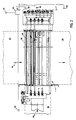
- Figure 1 shows a right angle flow-through jump transfer of the present invention, generally referred to by reference number 1.
- the jump transfer 1 has rollers 4, 6, 8, 10, 12, 14, 16 and 18. Interposed between rollers 6, 8, 10, 12 and 14 are V-shaped belts or tensioning strips 7, 9, 11 and 13. Between rollers 4 and 6 is rail 20 while rail 22 is positioned between rollers 16 and 18.
- Roller 18 is preferably a low pressure type roller; i.e., when the rail 22 is raised, the low pressure roller 18 stops rotating as a result of the weight of the article thereon. Thus, articles accumulate without damage to the articles. All the rollers are preferably mounted on self-aligning bearing blocks 21 with bronze bushings 23.
- the tensioning strips are operably mounted on pulleys 25 which are in turn mounted on shafts 27, 29 on opposing ends thereof.
- the shafts 27, 29 are mounted on a base 31 having bearing block 33, preferably having a bronze bushing.
- Shaft 29 is preferably free-wheeling, while one end of shaft 27 is preferably coupled to a conventional drive mechanism (not shown) for turning pulleys 25.
- the pulleys 25 consequently rotate the strips for carrying articles in the direction of arrow 35 while the strips are in the raised position.
- an input portion 24 of the conveyor is provided for moving articles in the direction towards the flow-through jump transfer 1 while output portions 26 and 28 are alternative output portions for directing flows out of the jump transfer 1.
- the path taken out of the jump transfer 1, i.e., either output portion 26 or 28, is determined by the condition of the flow of articles along various portions of the conveyor which will later be discussed.
- the ratio between the article velocity on conveyor portions 24, 28 and the article velocity along the rollers is 1:2.
- an article sensor 38 Alongside the jump transfer 1 and preferably disposed between rail 22 and roller 18 is an article sensor 38. Between rails 20 and 22 is disposed an article sensor 40 which is preferably a reflector-type capable of sensing across opposing angles defined by the rectangular configuration of the jump transfer 1.
- Article sensors 44, 46 and 48 are located near conveyor portions 24, 26 and 28, respectively. Sensors 38, 40, 44, 46 and 48 are connected to a programmable controller (PC) 50.
- PC programmable controller
- abutting rail 20 or 22 is brace member 30 or 32.
- Each of rails 20, 22, preferably has an L-shaped configuration having the bottom portion 52 coupled to at least one actuator cylinder 54 with a plunger 56 which protrudes downward.
- the actuator cylinder 54 is attached to a frame portion 58 connected to side frame 59.
- FIG. 3 further illustrates either brace member 30 or 32 coupled to lower frame 60 which is in turn connected to side frame 59.
- Each brace member 30, 32 has a channel-shaped plastic sleeve 61 coupled thereto to prevent abrasions occurring on the rails 20, 22.
- FIG 4 another actuator cylinder 62 is coupled to the lower frame 60.
- a horizontal support member 66 having inverted L-shaped members 68 and 70 attached thereto for supporting tensioning strips 7 and 13, respectively.
- C-shaped members 72, 74 Coupled above the intermediate portion of the horizontal support member 66 are C-shaped members 72, 74 for supporting tensioning strips 9 and 11.
- lubricated members 76, 78, 80 and 82 are manufactured by, for example, Nolu-S Company of Pennsylvania.
- the side surfaces of the edges of the lubricated members 76, 78, 80 and 82 which abut the strips 7, 9, 11 and 13 are preferably chamfered for providing relaxation to the sloping portions of the strips directly abutting the end pulleys (not shown).
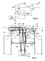
- FIG 6 a schematic view of the actuator cylinders 54 for operating the rails 20, 22 is shown.
- Each rail 20 or 22 has at least two cylinders 54 at opposing ends thereof (see, Figure 3 showing one end of rail 20).
- Cylinders 54 are double acting actuator cylinders having inlet 84 and outlet 85 (see, Figure 3) which connect to inlet 86 and outlet 88 lines.
- the inlet line 86 and outlet line 88 are coupled to dual air-line members 90 which, in turn, are coupled to an air supply 92.
- the double acting actuator cylinders 54 are coupled to 4-way solenoid valves (not shown) which, in turn, are joined to the PC 50.
- the PC 50 is programmed to detect by means of article sensor 44 the accumulation of articles flowing towards the jump transfer 1.
- sensor 38 detects articles
- rail 22 is lowered.
- sensor 40 detects articles on the strips 7, 9, 11, 13, rail 20 is raised.
- the PC 50 is programmed for a time delay between the lowering of rail 22 by cylinders 54 and the raising of the strips 7, 9, 11, 13 by cylinder 62 in order for articles to be transported to the conveyor portion 26 located perpendicular to conveyor portion 24.
- sensor 44 can detect accumulation of articles on conveyor portion 24. Once accumulation of articles is detected by sensor 44, the strips and rail 20 are raised, thereby diverting the flow of the articles toward conveyor portion 26, as shown by arrow 35.
- Shown in Figure 7 is a schematic view of the manner in which the rollers 4, 6, 8, 10, 13, 14, 16, 18 are driven by motor 94.
- Joined to roller 6 are belts 100 and 102 for operably coupling to rollers 4 and 8, respectively.
- Belt 102 similarly couples roller 6 to roller 8, while belt 104 joins roller 8 to roller 10.
- a belt (not shown) couples roller 10 to roller 12, while another belt (not shown) joins roller 12 to roller 14.
- Rollers 14 and 16 are joined by still another belt (not shown), while rollers 16 and 18 are coupled by yet another belt (not shown).
- Joined to pulley 124 of motor 94 are rollers 10 and 12 by belts 120 and 122, respectively.
- the aforementioned arrangement provides for a compact series of rollers effectively driven by a single motor 94.
- the belts have been referred to as being joined to the rollers, it should be understood that the belts are joined to pulleys which are coupled to the rollers.
- the invention has been particularly illustrated as being a jump transfer capable of diverting articles along conveyor portions 26 and 28. It should be understood that the invention can also function with the above-described jump transfer in conjunction with another jump transfer mechanism solely for diverting the articles at a right angle direction at the end flow of conveyor portion 28.
Landscapes
- Engineering & Computer Science (AREA)
- Mechanical Engineering (AREA)
- Control Of Conveyors (AREA)
Claims (12)
- Dispositif de transfert à renvoi à angle droit (1) pour un système de transport comprenant une pluralité de rouleaux parallèles (4,6,8,10,12,14,16,18) disposés en une série plane, qui comprend :(A) une pluralité de courroies souples(7,9,11,13) supportées par des premiers supports (66) prévus pour la mise en tension, la montée et la descente desdites courroies (7,9,11,13), lesdites courroies (7,9,11,13) étant interposées entre lesdits rouleaux (4,6,8,10,12,14,16,18) ;(B) au moins une structure de rails (20,22) placée près d'un bord dudit dispositif de transfert à angle droit (1) et supportée par au moins un premier cylindre d'actionneur (54) pour la montée et la descente de ladite structure de rails (20,22) en séquence avec les dites courroies (7,9,11,13) ;(C) des premiers moyens d'entraînement (94) pour entraîner ladite pluralité de rouleaux (4,6,8,10,12,14,16,18) ;(D) des deuxièmes moyens d'entraînement pour entraîner ladite pluralité de courroies (7,9,11,13) ; et(E) des premiers moyens de détection (44) pour détecter un paramètre prédéterminé dans le flux d'articles sur ledit dispositif de transfert à renvoi à angle droit (1).
- Dispositif de transfert à renvoi à angle droit (1) suivant la revendication 1, dans lequel chacune de ladite pluralité de courroies (7,9,11,13) est fonctionnellement associée à des poulies d'extrémité (25) accouplées auxdits deuxièmes moyens d'entraînement.
- Dispositif de transfert à renvoi à angle droit (1) suivant la revendication 2, dans lequel lesdits premiers supports (66) comprennent :(a) des bandes lubrifiantes rigides (76,78,80, 82) sur lesquelles reposent directement lesdites courroies (7,9,11,13) ;(b) des profilés (68,70,72,74) directement montés sous lesdites bandes lubrifiantes (76,78,80,82) ; et(c) un deuxième cylindre d'actionneur (62) pour déplacer les profilés (68,70,72,74) vers le haut ou le bas.
- Dispositif de transfert à renvoi à angle droit (1) suivant la revendication 3, dans lequel lesdits premiers moyens de détection (44) sont prévus pour activer les premier et deuxième cylindres d'actionneurs (54,62).
- Dispositif de transfert à renvoi à angle droit (1) suivant la revendication 1, comprenant en outre :(a) une partie de convoyeur d'entrée (24) qui dirige les articles vers ledit dispositif de transfert à renvoi à angle droit (1), et(b) une première et une deuxième parties de convoyeur de sortie (26,28) qui évacuent les articles du dit dispositif de transfert à renvoi à angle droit (1).
- Dispositif de transfert à renvoi à angle droit (1) suivant la revendication 5, dans lequel lesdits premiers moyens de détection comprennent :(a) un premier capteur (38) placé entre ledit dispositif de transfert (1) et ladite partie de convoyeur d'entrée (24) ; et(b) un deuxième capteur (40) capable de détecter la présence d'articles sur toute la surface couverte par ledit dispositif de transfert à renvoi à angle droit (1).
- Dispositif de transfert à renvoi à angle droit (1) suivant la revendication 6, comprenant en outre des deuxièmes moyens de détection (46,48) placés le long de l'entrée des première et deuxième parties de convoyeur (26,28) pour détecter un paramètre prédéterminé du flux d'articles sur ces parties.
- Dispositif de transfert à renvoi à angle droit (1) suivant la revendication 7, dans lequel les premier et deuxième cylindres d'actionneurs (54,62) et lesdits premiers et deuxièmes moyens de détection (38,40; 46,48) sont fonctionnellement reliés à des moyens de commande programmables (50) pour faire monter et descendre séquentiellement la pluralité de courroies (7,9,11,13) et la structure de rails (20,22) en fonction d'un paramètre prédéterminé du flux d'articles.
- Dispositif de transfert à renvoi à angle droit (1) suivant la revendication 8, dans lequel ladite structure de rails (20,22) comprend :
un premier rail (20) entre ladite partie de convoyeur d'entrée (24) et ledit dispositif de transfert à renvoi à angle droit (1) ; et
un deuxième rail (22) entre ledit dispositif de transfert à renvoi à angle droit (1) et ladite partie de convoyeur de sortie (28). - Dispositif de transfert à renvoi à angle droit (1) suivant la revendication 9, dans lequel ledit premier rail (20) et ledit deuxième cylindre d'actionneur (62) sont activés avec une temporisation par lesdits moyens de commande programmables (50).
- Dispositif de transfert à renvoi à angle droit (1) suivant la revendication 2,dans lequel lesdites poulies d'extrémité (25) sont fonctionnellement reliées à des arbres (27,29), au moins un desdits arbres (27) étant mis en rotation par lesdits deuxièmes moyens d'entraînement.
- Dispositif de transfert à renvoi à angle droit (1) suivant la revendication 11, dans lequel les dits arbres (27,29) sont fonctionnellement montés sur une base (31) comportant un bloc de palier (33) avec un coussinet.
Applications Claiming Priority (4)
| Application Number | Priority Date | Filing Date | Title |
|---|---|---|---|
| US7618387A | 1987-07-15 | 1987-07-15 | |
| US76183 | 1987-07-15 | ||
| US12918987A | 1987-12-07 | 1987-12-07 | |
| US129189 | 1987-12-07 |
Publications (2)
| Publication Number | Publication Date |
|---|---|
| EP0300122A1 EP0300122A1 (fr) | 1989-01-25 |
| EP0300122B1 true EP0300122B1 (fr) | 1991-12-18 |
Family
ID=26757757
Family Applications (1)
| Application Number | Title | Priority Date | Filing Date |
|---|---|---|---|
| EP19880102870 Expired EP0300122B1 (fr) | 1987-07-15 | 1988-02-26 | Dispositif de transfert à fonctionnement discontinu permettant le passage transversal, pour système de transport |
Country Status (4)
| Country | Link |
|---|---|
| EP (1) | EP0300122B1 (fr) |
| AU (1) | AU603432B2 (fr) |
| CA (1) | CA1312632C (fr) |
| DE (1) | DE3866983D1 (fr) |
Families Citing this family (11)
| Publication number | Priority date | Publication date | Assignee | Title |
|---|---|---|---|---|
| US4971190A (en) * | 1989-09-29 | 1990-11-20 | Automotion, Incorporated | Conveyor cross switch |
| IT1238227B (it) * | 1989-12-01 | 1993-07-12 | Modulo di smistamento per impianti di convogliamento a nastro e simili | |
| IT1243028B (it) * | 1990-09-21 | 1994-05-23 | Meccanizzazione Postale E Auto | Modulo di smistamento per apparati di convogliamento. |
| FI912244A0 (fi) * | 1991-05-09 | 1991-05-09 | Markku Koisti | Foerfarande och anordning foer transportering av styckegodset eller liknande till avlastningsstation. |
| ES2254491T3 (es) * | 2001-09-12 | 2006-06-16 | Solystic | Dispositivo de transferencia para transportador lineal. |
| DE202006000147U1 (de) * | 2006-01-05 | 2006-10-19 | Minda Industrieanlagen Gmbh | Fördereinrichtung |
| DE202010002285U1 (de) * | 2010-02-12 | 2011-08-23 | Ligmatech Automationssysteme Gmbh | Vorrichtung zum Rückführen von bearbeiteten Werkstücken |
| US9114939B2 (en) | 2013-03-31 | 2015-08-25 | Intelligrated Headquarters, Llc | Case turner conveying system |
| AU2015302099B2 (en) * | 2014-08-15 | 2019-11-21 | Dematic Corp. | Right angle transfer |
| BE1026817B1 (nl) * | 2018-11-30 | 2020-06-30 | Degramec Bvpa | Machine voor het verplaatsen van potten en gebruik van deze machine als verenkelaar of als overduwer |
| CN112320246A (zh) * | 2020-10-23 | 2021-02-05 | 上海中船临港船舶装备有限公司 | 一种型材自动喷码装置 |
Family Cites Families (2)
| Publication number | Priority date | Publication date | Assignee | Title |
|---|---|---|---|---|
| US3087597A (en) * | 1960-08-22 | 1963-04-30 | Otto G Jeddeloh | Unloading mechanism for sheethandling multideck conveyer |
| US3938646A (en) * | 1974-01-14 | 1976-02-17 | Umberto Brasa | Method and apparatus for deviating objects transported along a conveyor |
-
1988
- 1988-02-26 EP EP19880102870 patent/EP0300122B1/fr not_active Expired
- 1988-02-26 DE DE8888102870T patent/DE3866983D1/de not_active Expired - Fee Related
- 1988-02-26 CA CA000560007A patent/CA1312632C/fr not_active Expired - Fee Related
- 1988-03-08 AU AU12788/88A patent/AU603432B2/en not_active Ceased
Also Published As
| Publication number | Publication date |
|---|---|
| AU1278888A (en) | 1989-01-19 |
| CA1312632C (fr) | 1993-01-12 |
| DE3866983D1 (de) | 1992-01-30 |
| EP0300122A1 (fr) | 1989-01-25 |
| AU603432B2 (en) | 1990-11-15 |
Similar Documents
| Publication | Publication Date | Title |
|---|---|---|
| US4926999A (en) | Right angle flow-through jump transfer conveyor system | |
| US5165516A (en) | Three-way transfer conveyor | |
| US5901830A (en) | Bi-directional belt sorter | |
| US4730718A (en) | Bi-directional transfer mechanism | |
| US5609236A (en) | Roller conveying device | |
| JP5140601B2 (ja) | コンベヤ切換器 | |
| US5117961A (en) | Conveying apparatus and article diverter | |
| US4917232A (en) | Flexible conveyor belt supporting structure | |
| US4328889A (en) | Conveyor means | |
| US6619464B2 (en) | Vertical diverter assembly | |
| EP0300122A1 (fr) | Dispositif de transfert à fonctionnement discontinu permettant le passage transversal, pour système de transport | |
| US6648121B2 (en) | Deviating device for a conveyor | |
| US20090152074A1 (en) | Conveyor diverter | |
| MX2007003738A (es) | Clasificador bidireccional de correa con rodillos transversales en la parte superior con guia automatizada. | |
| US6523672B2 (en) | Zero-back-pressure conveyor with inverted roller belt loop | |
| NZ201726A (en) | Inflatable bag raised roller conveyor and independently raised drive roller | |
| IT8922564A1 (it) | Modulo di smistamento per impianti di convogliamento a nastro e simili | |
| CA1139254A (fr) | Transporteur a rouleaux entraines, avec dispositif de debrayage de l'organe moteur | |
| JP4828801B2 (ja) | コンベヤにおける搬送物の方向転換方法 | |
| US3219166A (en) | Roller conveyor | |
| EP0225810B1 (fr) | Convoyeur à éjection sélective | |
| US6062376A (en) | Zero back-pressure conveyor system | |
| US4946022A (en) | Article sorting switch | |
| US5685414A (en) | Zero back-pressure conveyor system | |
| AU725151B2 (en) | Bucket conveyor apparatus having improved infeed station |
Legal Events
| Date | Code | Title | Description |
|---|---|---|---|
| PUAI | Public reference made under article 153(3) epc to a published international application that has entered the european phase |
Free format text: ORIGINAL CODE: 0009012 |
|
| AK | Designated contracting states |
Kind code of ref document: A1 Designated state(s): DE FR GB IT |
|
| 17P | Request for examination filed |
Effective date: 19890603 |
|
| 17Q | First examination report despatched |
Effective date: 19910109 |
|
| ITF | It: translation for a ep patent filed | ||
| GRAA | (expected) grant |
Free format text: ORIGINAL CODE: 0009210 |
|
| AK | Designated contracting states |
Kind code of ref document: B1 Designated state(s): DE FR GB IT |
|
| REF | Corresponds to: |
Ref document number: 3866983 Country of ref document: DE Date of ref document: 19920130 |
|
| ET | Fr: translation filed | ||
| PLBE | No opposition filed within time limit |
Free format text: ORIGINAL CODE: 0009261 |
|
| STAA | Information on the status of an ep patent application or granted ep patent |
Free format text: STATUS: NO OPPOSITION FILED WITHIN TIME LIMIT |
|
| 26N | No opposition filed | ||
| PGFP | Annual fee paid to national office [announced via postgrant information from national office to epo] |
Ref country code: GB Payment date: 19940216 Year of fee payment: 7 |
|
| PGFP | Annual fee paid to national office [announced via postgrant information from national office to epo] |
Ref country code: FR Payment date: 19940223 Year of fee payment: 7 |
|
| PGFP | Annual fee paid to national office [announced via postgrant information from national office to epo] |
Ref country code: DE Payment date: 19940224 Year of fee payment: 7 |
|
| PG25 | Lapsed in a contracting state [announced via postgrant information from national office to epo] |
Ref country code: GB Effective date: 19950226 |
|
| GBPC | Gb: european patent ceased through non-payment of renewal fee |
Effective date: 19950226 |
|
| PG25 | Lapsed in a contracting state [announced via postgrant information from national office to epo] |
Ref country code: FR Effective date: 19951031 |
|
| PG25 | Lapsed in a contracting state [announced via postgrant information from national office to epo] |
Ref country code: DE Effective date: 19951101 |
|
| REG | Reference to a national code |
Ref country code: FR Ref legal event code: ST |
|
| PG25 | Lapsed in a contracting state [announced via postgrant information from national office to epo] |
Ref country code: IT Free format text: LAPSE BECAUSE OF NON-PAYMENT OF DUE FEES;WARNING: LAPSES OF ITALIAN PATENTS WITH EFFECTIVE DATE BEFORE 2007 MAY HAVE OCCURRED AT ANY TIME BEFORE 2007. THE CORRECT EFFECTIVE DATE MAY BE DIFFERENT FROM THE ONE RECORDED. Effective date: 20050226 |