EP0300143B2 - Butée à mâchoires - Google Patents
Butée à mâchoires Download PDFInfo
- Publication number
- EP0300143B2 EP0300143B2 EP88106790A EP88106790A EP0300143B2 EP 0300143 B2 EP0300143 B2 EP 0300143B2 EP 88106790 A EP88106790 A EP 88106790A EP 88106790 A EP88106790 A EP 88106790A EP 0300143 B2 EP0300143 B2 EP 0300143B2
- Authority
- EP
- European Patent Office
- Prior art keywords
- bolt
- housing
- spring
- sole
- sole clamp
- Prior art date
- Legal status (The legal status is an assumption and is not a legal conclusion. Google has not performed a legal analysis and makes no representation as to the accuracy of the status listed.)
- Expired - Lifetime
Links
Images


Classifications
-
- A—HUMAN NECESSITIES
- A63—SPORTS; GAMES; AMUSEMENTS
- A63C—SKATES; SKIS; ROLLER SKATES; DESIGN OR LAYOUT OF COURTS, RINKS OR THE LIKE
- A63C9/00—Ski bindings
- A63C9/08—Ski bindings yieldable or self-releasing in the event of an accident, i.e. safety bindings
- A63C9/084—Ski bindings yieldable or self-releasing in the event of an accident, i.e. safety bindings with heel hold-downs, e.g. swingable
- A63C9/0844—Ski bindings yieldable or self-releasing in the event of an accident, i.e. safety bindings with heel hold-downs, e.g. swingable the body pivoting about a transverse axis
-
- A—HUMAN NECESSITIES
- A63—SPORTS; GAMES; AMUSEMENTS
- A63C—SKATES; SKIS; ROLLER SKATES; DESIGN OR LAYOUT OF COURTS, RINKS OR THE LIKE
- A63C9/00—Ski bindings
- A63C9/005—Ski bindings with means for adjusting the position of a shoe holder or of the complete binding relative to the ski
-
- A—HUMAN NECESSITIES
- A63—SPORTS; GAMES; AMUSEMENTS
- A63C—SKATES; SKIS; ROLLER SKATES; DESIGN OR LAYOUT OF COURTS, RINKS OR THE LIKE
- A63C9/00—Ski bindings
- A63C9/08—Ski bindings yieldable or self-releasing in the event of an accident, i.e. safety bindings
- A63C9/085—Ski bindings yieldable or self-releasing in the event of an accident, i.e. safety bindings with sole hold-downs, e.g. swingable
- A63C9/08507—Ski bindings yieldable or self-releasing in the event of an accident, i.e. safety bindings with sole hold-downs, e.g. swingable with a plurality of mobile jaws
- A63C9/08521—Ski bindings yieldable or self-releasing in the event of an accident, i.e. safety bindings with sole hold-downs, e.g. swingable with a plurality of mobile jaws pivoting about a vertical axis, e.g. side release
-
- A—HUMAN NECESSITIES
- A63—SPORTS; GAMES; AMUSEMENTS
- A63C—SKATES; SKIS; ROLLER SKATES; DESIGN OR LAYOUT OF COURTS, RINKS OR THE LIKE
- A63C9/00—Ski bindings
- A63C9/08—Ski bindings yieldable or self-releasing in the event of an accident, i.e. safety bindings
- A63C9/085—Ski bindings yieldable or self-releasing in the event of an accident, i.e. safety bindings with sole hold-downs, e.g. swingable
- A63C9/08535—Ski bindings yieldable or self-releasing in the event of an accident, i.e. safety bindings with sole hold-downs, e.g. swingable with a mobile body or base or single jaw
- A63C9/0855—Ski bindings yieldable or self-releasing in the event of an accident, i.e. safety bindings with sole hold-downs, e.g. swingable with a mobile body or base or single jaw pivoting about a vertical axis
-
- A—HUMAN NECESSITIES
- A63—SPORTS; GAMES; AMUSEMENTS
- A63C—SKATES; SKIS; ROLLER SKATES; DESIGN OR LAYOUT OF COURTS, RINKS OR THE LIKE
- A63C9/00—Ski bindings
- A63C9/08—Ski bindings yieldable or self-releasing in the event of an accident, i.e. safety bindings
- A63C9/085—Ski bindings yieldable or self-releasing in the event of an accident, i.e. safety bindings with sole hold-downs, e.g. swingable
- A63C9/08557—Details of the release mechanism
- A63C9/08564—Details of the release mechanism using cam or slide surface
-
- A—HUMAN NECESSITIES
- A63—SPORTS; GAMES; AMUSEMENTS
- A63C—SKATES; SKIS; ROLLER SKATES; DESIGN OR LAYOUT OF COURTS, RINKS OR THE LIKE
- A63C9/00—Ski bindings
- A63C9/001—Anti-friction devices
Definitions
- the invention relates to a jaw body according to the preambles of claims 1, 10 and 12.
- a jaw body according to the preamble of claim 1 can be found in DE-A1-19 43 973, in particular in connection with FIG. 8.
- the bolt is designed as a threaded bolt that is screwed into a sleeve with an internal thread, which in turn sits in a vertical bore in the jaw body.
- the threaded bolt is screwed up or down in the sleeve and takes the sole holder with it.
- the sole holder is slidably mounted on a thread-free section of the threaded bolt.
- the helical spring is arranged between the underside of the threaded bolt head and the upper side of the sole holder, which is thereby elastically pushed downward against a stop ring provided on the threaded bolt above the thread.
- the device for adapting the sole holder to ski shoe soles of different thicknesses is thus designed as a screw connection between the threaded bolt and the threaded sleeve attached in the jaw.
- a spring device is provided which allows the sole hold-down device to perform an elastic evasive movement when there is snow on the sole of the ski boot and the ski.
- AT-PS 375 269 already describes a jaw body in which a sole holder which can be rotated about a vertical bolt in a horizontal plane can be pivoted to a limited extent in a vertical plane on a transverse axis which penetrates the bolt.
- the flat rear side of the sole holder is acted upon by a piston from the release spring, which tries to pivot the lever arm of the sole holder, which is removed from the spring, against the upper side of the ski.
- This jaw body has the disadvantage that the sole thickness may have little scope to make a correct fixing by the sole holder possible.
- the manufacture of the sole holder is difficult since it is penetrated by a hole which extends obliquely to the upper and lower boundary surface and is approximately oblong in plan view.
- FIGS. 7 and 8 a toe is shown in FIGS. 7 and 8, in which the sole holder, which is under the influence of a spring pushing it upwards, is displaceably guided on a bolt.
- the bore of the sole holder has thread segments in two diametrically opposite areas, which extend over approximately 90 °.
- the bolt is flattened on two sides and carries threaded segments between the flattened areas, which also extend over approximately 90 °.
- the threaded segments of the bolt and the bore can be detached from each other for the adjustment process (see Fig. 8) and for fixing of the sole holder are brought back into engagement with one another (see FIG. 7).
- An automatic adjustment of the sole holder is not possible with this version. Rather, the desired position of the sole holder, as described, must be set by hand.
- Document FR-A-2,556 602 describes a bakery body which consists of a bearing block to be fastened to a ski and a housing which carries a sole hold-down and accommodates a release spring and which can be pivoted in a horizontal plane against the force of the release spring.
- a vertically extending bolt which serves as the pivot axis, is arranged in the housing and is secured against axial displacement relative to the bearing block.
- a similar jaw body is shown in document FR-A-2,537,442.
- This has a bearing block to be fastened to a ski and a housing carrying a sole holder and receiving a release spring, which housing can be pivoted to a limited extent against the force of the release spring relative to the bearing block in a plane parallel to the top of the ski and in a normal plane to the latter.
- a vertically extending bolt serving as a pivot axis for the housing is arranged in the bearing block with a ball-joint-like head.
- the bolt is a screw bolt that is screwed into a threaded bore in the housing or the bearing block.
- the screw bolt In order to adjust the height of the sole hold-down to differently thick shoe soles, the screw bolt must be turned, which leads to the disadvantages mentioned above.
- the object of the invention is to eliminate the disadvantages of the known designs and to create a jaw body which, on the one hand, is simple in its construction and, on the other hand, enables the sole holder to be adjusted automatically even if the thickness of the shoe sole varies within the prescribed tolerance limits ( see currently ⁇ NORM S 4035 or DIN 7880, Part 1: 19 ⁇ 1 mm for adults, and ⁇ NORM S 4036 or DIN 7880, part 2: 15 ⁇ 2 mm for children).
- claim 2 reduces the overall height of the jaw body, especially since part of the length of the compression spring is located within the sole holder.
- the measure of claim 3 ensures that, on the one hand, the sole holder is pressed onto the ski boot with sufficient force, but that this pressure is not so great that the pretensioning of the release spring has to be feared.
- the subject matter of claim 4 defines the position of the sole holder in the jaw body in a simple manner.
- Claim 5 describes the use of a cheek body according to the invention in a safety ski binding with a compensating lever, as described, for example, in AT-PS 368 396 and which enables compensation of the additional frictional forces that occur on the sole holder in the event of a backward fall.
- a compensating lever as described, for example, in AT-PS 368 396 and which enables compensation of the additional frictional forces that occur on the sole holder in the event of a backward fall.
- an elastic element is arranged between the sole holder and the compensating lever, but this is only used to enable a pivoting movement of the compensating lever without the sole holder changing its vertical position.
- the elastic element does not influence the height of the release lever.
- the arrangement of a coil spring is particularly favorable for manufacturing reasons.
- the sole holder is secured against lateral pivoting.
- Claim 7 expresses the fact that the measure according to the invention can also be used advantageously with heel cheeks.
- the distance between the sole holder and the underside of the housing, which is automatically set by the ski boot via the helical spring, is essentially determined.
- a front jaw is characterized in claims 12 and 13, in which the bolt which forms the pivot axis for the housing, as is also known, is held in the bearing block against axial displacement and in which the housing is guided on the bolt so as to be displaceable in the vertical direction is.
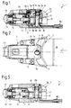
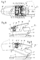
- Fig. 1 is a vertical longitudinal central section through a first embodiment designed as a front jaw in the starting position and Fig. 2 is a corresponding partially sectioned plan view. 3 and 4, the cheek body is shown in a partially sectioned side view with a thin or thick shoe sole inserted.
- 5 shows a further jaw body, likewise designed as a front jaw, in a vertical longitudinal central section.
- Fig. 6 a third front jaw is shown in the longitudinal central section. This is shown in FIG. 7 in a partially sectioned side view with the shoe sole inserted.
- Fig. 6a is a section on a larger scale along the line VIa - VIa in Fig.
- FIG. 6 through a detail of the toe and Fig. 6b is a variant thereof.
- 8 and 9 show a cheek body which is designed as a heel holder, in a partially sectioned side view in the idle state and during the boarding process.
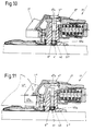
- 10 and 11 or 12 and 13 vertical vertical central sections are shown by further front jaws according to the invention similar to FIGS. 1 and 3.
- 14 is a top view of FIG. 12.
- a jaw body shown in FIGS. 1-4 is designed as a front jaw and is designated 1 in its entirety. It has a housing 2 which can be fastened in a known manner to the top of a ski (not shown) by means of screws (not shown) and in which a support body 3 which is approximately angular in longitudinal section is arranged. Of this, one leg 3a is arranged essentially parallel to the top of the ski. The other bar 3b runs vertically to the top of the ski and carries at its upper end an axis 4 which runs in the direction of the ski and parallel to the top of the ski. On this axis 4, an angle lever 5 is mounted.
- a vertical bore 5c is recessed, which is penetrated by a bolt 6, the head 6a of which rests on the leg 5a.
- the lower end of the bolt 6 is guided in a bore 3c of the leg 3a.
- the bore 3c is located in a cup-shaped bulge 3d of the leg 3a.
- the lower end of the bolt 6 is provided with a thickening 6b, which limits the displacement of the bolt 6 and thus the pivot angle of the angle lever 5.
- the bolt 6 passes through the stepped bore 7a of a sole holder 7, which rests on the bulge 3d of the leg 3a when the ski boot is not in use (see FIG. 1). Furthermore, the bolt 6 is surrounded by a helical spring 8, which is arranged with its lower end in the stepped bore 7a and with the other, upper end on the underside of the leg 5a, optionally with the interposition of a locking washer 9, which is supported in a groove of the bolt 6 engages. There is play between the locking washer 9 and the underside of the leg 5a, which allows the angle lever 5 to be pivoted.
- the remaining structure 3a of the toe piece 1 is of a known type.
- the leg 3a of the supporting body 3 carries two vertical axes 10 at a lateral distance from the vertical longitudinal center plane of the toe piece 1, on which lateral angle levers 11 are mounted, one of which is one leg for laterally holding the shoe sole 12a, 12'a in the toe pieces 1 used shoe 12, 12 'is used (see FIGS. 3 and 4).
- the bias of the release spring 13 can be adjusted by means of a sleeve 14 with an internal thread.
- This sleeve 14 is screwed onto the threaded section of a pull rod 15 which passes through the release spring 13 in the center.
- the pull rod 15 carries a slide 17. On the pull rod 15, a pull is exerted by the release spring 13 towards the ski tip.
- the slide 17 acts on each of the two lateral angle levers 11, and via this the angle lever 5.
- Fig. 1 the toe 1 is shown before the ski boot is used.
- the approximately wedge-shaped tapered tip of the shoe sole 12a or 12'a is inserted obliquely from above into the gap between the leg 3a of the support body 3 and the sole holder 7.
- the ski boot 12 or 12 ' is depressed so that it is with its sole 12a or 12'a rests on the leg 3a or on a base plate 18 (see FIGS. 3 and 4).
- the sole holder 7 is raised against the force of the coil spring 8 in accordance with the thickness of the shoe sole 12a or 12'a.
- This position of the sole holder 7 is shown in FIG. 3 when using a ski shoe with a thickness h 1 of the shoe sole 12 and when using a ski shoe with a thickness h 2 of the shoe sole 12'a.
- the front jaw 1 'shown in Fig. 5 is very similar to that described first. It differs from this only in that the head 6'a of the bolt 6 'is mounted in the housing 2' itself, and that the release spring 13 'housed in the housing 2' only acts on the two lateral angle levers 11 ', which act on the side Bracket of the shoe sole are intended.
- this design is somewhat simpler in structure than the one dealt with first, it has the disadvantage that it does not compensate for the frictional forces that occur backwards on the sole holder in the event of a fall.
- the front jaw 1 '' according to FIGS. 6 and 7 essentially corresponds to the front jaw 1 according to FIGS. 1-4. It differs from this only in that the bolt 6 '' in the region of the one remote from the release spring 13 '' Half of its lateral surface is provided with ribs 6''c, which run in the top half of the bolt axis and in the circumferential direction of the bolt 6 '' and which are approximately crescent in plan view, with corresponding grooves 7''b in the associated half of the approximately elliptical bore of the sole holder 7 '' .
- the leaf spring 20 is bent back after the sole holder 7 ′′ has automatically adapted to the thickness of the sole 12 ′′ a, and the ribs 6 ′′ c of the bolt 6 ′′ engage in the grooves 7 ′′ b of the sole holder 7 ′′, which is thereby fixed in its height position relative to the base plate 18 ′′ (cf. FIG. 7).
- FIG. 6a illustrates on a larger scale the configuration of the ribs 6 ′′ c of the bolt 6 ′′ and the grooves 7 ′′ b of the sole holder 7 ′′. It should be noted that the sole holder 7 ′′ can be displaced in the vertical direction relative to the bolt 6 ′′.
- the variant of a sole holder 7 IV according to FIG. 6b differs from the previously described embodiment in that the bolt 6 IV is flattened laterally following the ribs 6 IV c, and that the sole holder 7 IV has guides corresponding to the flats. As a result, the sole holder 7 IV is secured against lateral pivoting out.
- FIGS. 8 and 9 relate to a jaw body which is designed as a heel holder 30.
- This heel holder 30 has a bearing block 31 which can be moved on a guide rail 32 in the longitudinal direction of the ski and can be fixed in a known manner in the selected position by means of a not shown locking device.
- In the bearing block 31 there is a transverse axis 33 at the end remote from the sole holder 7 ′′ ′′, on which the housing 2 ′′ ′′, which has a cross section and which carries a step spur 35 and the sole holder 7 ′′ ′′, is pivotably mounted .
- An axis 36 is fastened in the housing 2 '' 'and forms the pivot axis for a release lever 37.
- the heel holder 30 can be opened arbitrarily in a known manner by means of a transverse pin 38 which is attached to the release lever 37 and passes through the elongated holes (not shown) in the housing 2 '' '.
- a bolt 6' '' which extends approximately normal to the guide rail 32 and on which the sole holder 7 '' 'is slidably guided is fastened in the position according to FIG. 8.
- the sole holder 7 '' ' is pressed by the coil spring 8' '' against the top of the heel 12 '' '.
- the other components of the heel holder 30 are of a known type, which is why the arrangement of the release spring, the control lever, the suspension fork and the control cam assigned to the control lever will not be discussed in detail.
- the toe 1 V according to FIGS. 10 and 11 has, in contrast to those previously treated Front jaws a bracket 31 V to be fastened on the top of the ski, in which the bolt 6 V is mounted so that it can be moved vertically.
- the bearing block 31 V has in its lower region a frustoconical recess 40 which is open at the bottom and into which the lower end of the bolt 6 V projects.
- the coil spring 8 V is arranged, which is supported at one end on the ceiling 40a of the recess 40 and at the other end on a disk 41 which is placed on the bolt 6 V and riveted to it.
- the bolt 6 V carries at its upper end a head 6 V a, which is used for mounting the housing 2 V , which is provided with a sole holder 7 V at its rear end.
- the housing 2 V can not only be pivoted laterally about the bolt 6 V , but also a vertical pivoting of the housing 2 V is possible, especially since the underside of the head 6 V is conical.
- front jaw 1 VI essentially consists of a bearing block 31 and a VI of the sole holder 7 carrying VI and the release spring 13 VI female housing 2 VI.
- the housing is mounted displaceably relative to the bolt 6 VI against the force of the coil spring 8 VI .
- the bolt 6 VI has in its central region an annular groove 6 VI d delimited by a collar 6 VI e, in which a shoulder 31 VI a of the bearing block 31 VI engages radially.
- the bearing bore for the upper end of the bolt 6 VI is recessed in the housing 2 VI itself, whereas the lower bearing bore, formed as a stepped bore 2 VI b, is located in a shoulder 2 VI a of the housing 2 VI .
- the coil spring 8 VI is arranged on the tapered lower end 6 VI f of the bolt 6 VI adjoining the collar 6 VI e.
- the upper end thereof is supported on the collar 6 VI e of the bolt 6 VI , whereas the lower end is supported by the step of the stepped bore 2 VI b in the approach 2 VI a of the housing 2 VI and is surrounded by this approach 2 VI a.
- a set screw 34 running in the transverse direction of the front jaw 1 VI is rotatable in its central region, but is secured against axial displacement.
- the threaded pin 34 carries opposing threaded sections, which are not shown in FIG Intervene nuts. These are rotatably mounted in invisible levers which laterally enclose the shoe sole 12 VI a. These levers only serve to hold the shoe sole 12 VI a laterally. However, they cannot be swung out sideways if the skier falls over. Rather, the lateral swiveling is caused by the housing 2 VI in the event of a fall.
- the other components of the toe 1 VI are known (see FR-PS 2 556 602) and are not the subject of the present invention, which is why their description is omitted.
- FIGS. 12 and 13 shows a variant of the embodiment according to FIGS. 12 and 13.
- This variant is characterized in that the two levers 50a, 50b, which laterally enclose the shoe sole 12 VI a, are not penetrated by a threaded pin, but by a smooth bolt 34 '.
- the levers 50a, 50b are mounted on vertical axes 51a, 51b, which are anchored with their lower ends in the housing 2 VI .
- Coil springs 54a, 54b are accommodated in the two stepped bores 52a, 52b.
- Each coil spring 54a or 54b is supported at one end on the step of the stepped bore 52a or 52b and at the other end on a washer 55a or 55b which is riveted to the end of
- the housing 2 VI is pivoted about the bolt 6 VI when the skier falls, whereas the two levers 50a, 50b essentially do not change their position relative to the housing 2 VI .
- the sole holder does not necessarily have to be supported on the supporting body or on the housing in the rest position; rather, it can also be supported on a disk or an intermediate sleeve, which surrounds the bolt with play and rests on the support body or on the housing.
- the sole holder may also be formed approximately V-shaped in plan view. The two legs of the V exert a downward pressure on the sole of the shoe on both sides of the vertical longitudinal median plane of the ski boot.
- the spring elements which are shown as coil springs in all exemplary embodiments, can be formed by disk spring assemblies, plastic or rubber elements. The preload of the spring elements is 5 - 90 ° when the ski boot is inserted the preload of the release spring.
Landscapes
- Footwear And Its Accessory, Manufacturing Method And Apparatuses (AREA)
Claims (13)
- Corps de mâchoire pour fixations de sécurité pour skis, comprenant un boîtier s'étendant dans le sens longitudinal de la mâchoire et comprenant un ressort de déclenchement ainsi qu'un cale-semelle (7 - 7IV) qui est disposé à coulissement de façon délimitée sur un tenon (6) reposant sensiblement perpendiculairement au côté supérieur du ski, lequel cale-semelle (7 - 7IV) sous l'influence d'un élément élastique ou à ressort l'appuyant contre le côté supérieur de la semelle de chaussure (12a, 12'a) disposé verticalement, de préférence un ressort hélicoïdal (8 - 8'''), le tenon (6) et le ressort (8 - 8''') faisant partie d'un dispositif pour adapter le cale-semelle à des semelles de chaussures de ski de différentes épaisseurs, caractérisé en ce que le tenon (6) logé par son extrémité inférieure dans le boîtier ou dans un corps de support de la mâchoire est conçu sans filetage de sorte que le cale-semelle (7 - 7''') est guidé à coulissement sur le tenon (6) et en ce que la course de coulissement du cale-semelle (7 - 7IV) est dimensionnée de telle sorte que le cale-semelle seul peut s'adapter automatiquement par coulissement contre l'élément élastique ou à ressort (8 - 8''') à des semelles de chaussures de ski de différentes épaisseurs (figures 1 - 9).
- Corps de mâchoire selon la revendication 1, caractérisé par le fait que le ressort hélicoïdal (8 - 8'') prend appui, d'une part, contre le gradin d'un perçage étagé (7a - 7''a) pratiqué dans le cale-semelle (7 - 7'') et, d'autre part, respectivement contre le boîtier (2 - 2'') ou contre un disque d'arrêt (9 - 9'') enfilé sur le tenon (6 - 6'') (figures 1-7).
- Corps de mâchoire selon la revendication 1, caractérisé par le fait que la précharge du ressort hélicoïdal (8 - 8''') représente 5-90 % de la précharge du ressort de déclenchement (11) lorsque la chaussure de ski est engagée.
- Corps de mâchoire selon l'une des revendications 1-3, caractérisé par le fait que le cale-semelle (7 - 7''') prend respectivement appui dans la position de repos, par son extrémité inférieure, contre le boîtier (2 - 2''') ou contre le corps de support (3 - 3''), sous l'influence du ressort hélicoïdal (8 - 8'''), ledit boitier (2''') portant éventuellement un éperon (35) repose-pied.
- Corps de mâchoire selon l'une des revendications 1-4, caractérisé par le fait que l'extrémité supérieure du tenon (6, 6'') est montée, d'une manière connue par elle-même, dans un levier de compensation (6, 6') pouvant pivoter, sur le corps de support (3, 3''), autour d'un axe (4, 4') s'étendant parallèlement à la face supérieure du ski et transversalement par rapport à la direction longitudinale de la mâchoire ; et par le fait que le ressort hélicoïdal (8, 8'') est interposé entre le levier de compensation (5, 5') et le cale-semelle (7, 7'') (figures 1-4, 6 et 7).
- Corps de mâchoire selon l'une des revendications 1-5, caractérisé par le fait que le tenon (6IV) est aplati latéralement dans sa région centrale ; et par le fait que le calesemelle (7IV) présente des guides correspondant à ces méplats (figure 6b).
- Corps de mâchoire selon l'une des revendications 1-4, caractérisé par le fait que le boîtier (2''') est monté pivotant sur un axe transversal (33) à l'extrémité éloignée du cale-semelle (7'''), d'une manière connue par elle-même (figures 8 et 9).
- Corps de mâchoire selon l'une des revendications 5-7, caractérisé par le fait que le tenon (6'') porte dans sa région centrale, sur la moitié de sa périphérie qui est tournée à l'opposé du ressort de déclenchement (13''), des nervures (6''c) sensiblement en forme de croissants observées pardessus selon l'axe dudit tenon ; et par le fait que le perçage (7''a) pratiqué dans le cale-semelle (7'') est élargi par rapport au diamètre du tenon - en observant dans le sens longitudinal de la mâchoire -, l'une des moitiés du perçage présentant des gorges (7''b) pouvant être mises en prise avec les nervures (6''c) du tenon (6''), en s'opposant à la force d'un ressort (20) (figure 6a).
- Corps de mâchoire selon la revendication 8, caractérisé par le fait que le cale-semelle (7'') est sollicité, sur son côté tourné vers le ressort de déclenchement (13), par le ressort qui est réalisé sous la forme d'une lame de ressort (20), et a tendance à séparer les gorges (7''b) du cale-semelle (7'') d'avec les nervures (6''c) du tenon (6'') (figure 6).
- Corps de mâchoire pour fixations de sécurité pour skis, comprenant un sabot de montage à fixer sur un ski ainsi qu'un boitier portant un cale-semelle et un ressort de déclenchement qui peut être animé d'un pivotement limité par rapport au sabot de montage en s'opposant à la force du ressort de déclenchement, dans le sabot de montage est disposé un tenon s'étendant verticalement, servant d'axe de pivotement pour le pivotement horizontal, et assure le montage du boitier par son articulation supérieure, caractérisé en ce que le tenon exempt de filetage (6V) est coulissable axialement et est soumis à l'influence d'un ressort hélicoïdal (8V) qui pousse le cale-semelle contre la face supérieure de la semelle, et en ce que la course de coulissement du tenon (6V) est dimensionnée de telle sorte que le cale-semelle seul par coulissement du tenon contre le ressort hélicoïdal est automatiquement adaptable aux semelles de chaussures de ski de différentes épaisseurs.
- Corps de mâchoire selon la revendication 10, caractérisé par le fait que le ressort hélicoïdal (8V) est logé dans un évidement (40) du sabot de montage (31V), ouvert vers le bas, et prend appui par son extrémité supérieure contre le sommet (40a) dudit évidement (40) et, par son extrémité inférieure, contre un disque (41) riveté sur le tenon (6V).
- Corps de mâchoire pour fixations de sécurité pour skis, comprenant un sabot de montage devant être fixé sur un ski ainsi qu'un boîtier qui porte un cale-semelle renferme un ressort de déclenchement et peut pivoter en s'opposant à la force du ressort de déclenchement, un tenon, logé dans le boîtier dans lequel il s'étend verticalement et auquel il sert d'axe de pivotement, étant empêché de coulisser axialement par rapport au sabot de montage, caractérisé en ce que sur le tenon exempt de filetage (6VI) sur lequel est logé de façon coulissante le boîtier (2VI) est disposé un élément élastique ou à ressort, de préférence un ressort hélicoïdal (8VI) qui s'appuie par son extrémité supérieure sur un collet (6VIe) du tenon (6VI) et par son extrémité inférieure sur un appendice (2VIa) du boitier (2VI), et en ce que la course de coulissement du boîtier est dimensionnée de telle sorte que le cale-semelle (7VI) uniquement par coulissement du boîtier contre l'élément élastique ou à ressort peut s'adapter automatiquement à des semelles de chaussures de ski de différentes épaisseurs (figures 12 et 13).
- Corps de mâchoire selon la revendication 12, dans lequel deux leviers emprisonnant latéralement la semelle de la chaussure, et réglables autour d'axes verticaux, sont articulés sur le boîtier, caractérisé par le fait que les deux leviers (50a, 50b) sont traversés par un tenon lisse (34') dans les deux régions extrêmes duquel est respectivement disposé un élément élastique, de préférence un ressort hélicoïdal (54a, 54b) repoussant le levier (50a, respectivement 50b), qui lui est associé, vers le plan médian longitudinal vertical dudit corps de mâchoire (figure 14).
Applications Claiming Priority (2)
| Application Number | Priority Date | Filing Date | Title |
|---|---|---|---|
| AT1880/87 | 1987-07-24 | ||
| AT1880/87A AT392594B (de) | 1987-07-24 | 1987-07-24 | Backenkoerper fuer sicherheitsskibindungen |
Publications (4)
| Publication Number | Publication Date |
|---|---|
| EP0300143A2 EP0300143A2 (fr) | 1989-01-25 |
| EP0300143A3 EP0300143A3 (en) | 1989-03-22 |
| EP0300143B1 EP0300143B1 (fr) | 1992-06-03 |
| EP0300143B2 true EP0300143B2 (fr) | 1997-08-20 |
Family
ID=3523014
Family Applications (1)
| Application Number | Title | Priority Date | Filing Date |
|---|---|---|---|
| EP88106790A Expired - Lifetime EP0300143B2 (fr) | 1987-07-24 | 1988-04-28 | Butée à mâchoires |
Country Status (5)
| Country | Link |
|---|---|
| US (1) | US4960289A (fr) |
| EP (1) | EP0300143B2 (fr) |
| JP (1) | JPS6449584A (fr) |
| AT (1) | AT392594B (fr) |
| DE (1) | DE3871631D1 (fr) |
Families Citing this family (11)
| Publication number | Priority date | Publication date | Assignee | Title |
|---|---|---|---|---|
| AT388677B (de) * | 1987-09-09 | 1989-08-10 | Tyrolia Freizeitgeraete | Vorderbacken fuer sicherheitsskibindungen |
| AT391089B (de) * | 1988-12-20 | 1990-08-10 | Tyrolia Freizeitgeraete | Vorderbacken |
| FR2684016B1 (fr) * | 1991-11-25 | 1994-01-14 | Salomon Sa | Element de fixation de securite de ski alpin. |
| DE4238657A1 (de) * | 1992-11-16 | 1994-05-19 | Marker Deutschland Gmbh | Auslösende Skibindung |
| FR2707514B1 (fr) * | 1993-07-16 | 1995-09-29 | Salomon Sa | Elément de fixation de ski alpin. |
| FR2740695B1 (fr) * | 1995-11-07 | 1998-01-02 | Look Fixations Sa | Fixation de ski avec indicateur de precontrainte |
| US6105994A (en) * | 1997-04-09 | 2000-08-22 | Parris; James E. | Step-in binding having safety release mechanism for Telemark ski |
| DE19854917B4 (de) | 1998-11-27 | 2008-07-03 | Siemens Ag | Verfahren zur Bildrekonstruktion für ein CT-Gerät |
| FR2966747B1 (fr) * | 2010-10-29 | 2013-01-11 | Salomon Sas | Fixation de securite pour la pratique du ski. |
| DE102013009762A1 (de) * | 2013-06-10 | 2014-12-11 | Andreas Allmann | Sicherheitsskibindungssystem |
| AT519786B1 (de) * | 2017-03-16 | 2022-08-15 | Tyrolia Tech Gmbh | Sicherheitsskibindung |
Family Cites Families (16)
| Publication number | Priority date | Publication date | Assignee | Title |
|---|---|---|---|---|
| AT4036B (fr) | 1899-04-10 | 1901-05-10 | Emile Sterne | |
| AT4035B (fr) | 1899-10-17 | 1901-05-10 | Hans Miksch | |
| AT225587B (de) * | 1961-01-04 | 1963-01-25 | Karl Kinzl | Sicherheits-Skibindung |
| DE1179141B (de) * | 1961-08-12 | 1964-10-01 | Hannes Marker | Sicherheits-Vorderbacken fuer Skibindungen |
| FR1603205A (fr) * | 1968-09-06 | 1971-03-22 | ||
| DE1801314A1 (de) * | 1968-10-04 | 1970-05-06 | Marker Hannes | Spitzenhaltevorrichtung fuer Sicherheits-Skibindungen |
| DE2135808A1 (de) * | 1971-07-17 | 1973-01-25 | Benner Ohg K | Skibindung |
| DE2259819A1 (de) * | 1972-12-07 | 1974-06-12 | Ver Baubeschlag Gretsch Co | Haltebacken fuer skibindungen mit hoehenverstellbarem sohlenhalter |
| FR2259630B1 (fr) * | 1974-02-04 | 1978-03-24 | Beyl Jean Joseph Alfred | |
| FR2314742A1 (fr) * | 1975-06-20 | 1977-01-14 | Salomon & Fils F | Fixation de securite pour ski a compensation automatique des contraintes parasites |
| JPS5322493A (en) * | 1976-08-13 | 1978-03-01 | Shimadzu Corp | Offering a pparatus for speciment to automatic analyzer |
| AT368396B (de) * | 1980-07-24 | 1982-10-11 | Tyrolia Freizeitgeraete | Backen |
| AT372616B (de) * | 1982-04-29 | 1983-10-25 | Tyrolia Freizeitgeraete | Backen, insbesondere vorderbacken |
| AT375269B (de) * | 1982-05-19 | 1984-07-25 | Tyrolia Freizeitgeraete | Backen, insbesondere vorderbacken |
| FR2537442A1 (fr) * | 1982-12-13 | 1984-06-15 | Salomon & Fils F | Fixation de securite pour ski |
| FR2556602B1 (fr) * | 1983-12-20 | 1986-10-24 | Salomon Sa | Fixation de securite pour ski, et ski muni d'une telle fixation |
-
1987
- 1987-07-24 AT AT1880/87A patent/AT392594B/de not_active IP Right Cessation
-
1988
- 1988-04-28 EP EP88106790A patent/EP0300143B2/fr not_active Expired - Lifetime
- 1988-04-28 DE DE8888106790T patent/DE3871631D1/de not_active Expired - Lifetime
- 1988-07-14 US US07/220,032 patent/US4960289A/en not_active Expired - Fee Related
- 1988-07-25 JP JP63183737A patent/JPS6449584A/ja active Pending
Also Published As
| Publication number | Publication date |
|---|---|
| EP0300143B1 (fr) | 1992-06-03 |
| DE3871631D1 (de) | 1992-07-09 |
| JPS6449584A (en) | 1989-02-27 |
| US4960289A (en) | 1990-10-02 |
| ATA188087A (de) | 1989-01-15 |
| AT392594B (de) | 1991-04-25 |
| EP0300143A3 (en) | 1989-03-22 |
| EP0300143A2 (fr) | 1989-01-25 |
Similar Documents
| Publication | Publication Date | Title |
|---|---|---|
| DE3310739C2 (fr) | ||
| DE4137757A1 (de) | Lenkrolle, insbesondere fuer verfahrbare krankenbetten | |
| DE2627305A1 (de) | Skisicherheitsbindung | |
| DE3020346C2 (fr) | ||
| DE69300905T2 (de) | Bremsvorrichtung besonders für Rollschuhe. | |
| EP0300143B2 (fr) | Butée à mâchoires | |
| DE2402974A1 (de) | Kombination aus skistiefel und skibindung | |
| DE2916348A1 (de) | Sicherheitsbindung fuer ski mit seitlicher ausloesung | |
| CH651761A5 (de) | Vorderbacken einer sicherheitsskibindung. | |
| DE2812149A1 (de) | Skisicherheitsbindung | |
| DE3143576C2 (de) | Backen, insbesondere Vorderbacken, für Sicherheitsskibindungen | |
| CH652575A5 (de) | Skischuh. | |
| EP0217322A2 (fr) | Fixation de sécurité pour ski | |
| EP0098515A1 (fr) | Dispositif de réglage en longueur pour fixations de ski | |
| DE2356908C3 (de) | Haltekopf für eine Sicherheitsbindung | |
| DE4424737C1 (de) | Snowboardbindung | |
| EP0408855B1 (fr) | Mâchoire avant | |
| EP0080060B1 (fr) | Talonnière pour fixation de ski | |
| DE2528578A1 (de) | Sicherheitsbindung fuer skischuhe | |
| DE69602509T2 (de) | Schuhrückhaltevorrichtung auf einem Snowboard bzw. Ski oder ähnlichem | |
| EP0189562A1 (fr) | Talonnière pour fixation de ski | |
| DE1956653A1 (de) | Vorderbacken fuer Sicherheits-Skibindungen | |
| AT390382B (de) | Vorderbacken fuer sicherheitsskibindungen | |
| DE2707838A1 (de) | Sicherheitsskibindung mit an einem grundkoerper schwenkbar angeordnetem sohlenhalter und einer eingebauten skibremse | |
| AT390381B (de) | Backenkoerper fuer sicherheitsskibindungen |
Legal Events
| Date | Code | Title | Description |
|---|---|---|---|
| PUAI | Public reference made under article 153(3) epc to a published international application that has entered the european phase |
Free format text: ORIGINAL CODE: 0009012 |
|
| AK | Designated contracting states |
Kind code of ref document: A2 Designated state(s): CH DE FR LI |
|
| PUAL | Search report despatched |
Free format text: ORIGINAL CODE: 0009013 |
|
| AK | Designated contracting states |
Kind code of ref document: A3 Designated state(s): CH DE FR LI |
|
| 17P | Request for examination filed |
Effective date: 19890410 |
|
| 17Q | First examination report despatched |
Effective date: 19900517 |
|
| RAP1 | Party data changed (applicant data changed or rights of an application transferred) |
Owner name: TMC CORPORATION |
|
| GRAA | (expected) grant |
Free format text: ORIGINAL CODE: 0009210 |
|
| AK | Designated contracting states |
Kind code of ref document: B1 Designated state(s): CH DE FR LI |
|
| REF | Corresponds to: |
Ref document number: 3871631 Country of ref document: DE Date of ref document: 19920709 |
|
| ET | Fr: translation filed | ||
| REG | Reference to a national code |
Ref country code: CH Ref legal event code: PUE Owner name: HTM SPORT- UND FREIZEITGERAETE GMBH |
|
| RAP2 | Party data changed (patent owner data changed or rights of a patent transferred) |
Owner name: HTM SPORT- UND FREIZEITGERAETE GESELLSCHAFT M.B.H. |
|
| REG | Reference to a national code |
Ref country code: FR Ref legal event code: TP |
|
| PLBI | Opposition filed |
Free format text: ORIGINAL CODE: 0009260 |
|
| 26 | Opposition filed |
Opponent name: SALOMON S.A. Effective date: 19930220 |
|
| REG | Reference to a national code |
Ref country code: CH Ref legal event code: PFA Free format text: HTM SPORT- UND FREIZEITGERAETE AKTIENGESELLSCHAFT |
|
| RAP2 | Party data changed (patent owner data changed or rights of a patent transferred) |
Owner name: HTM SPORT- UND FREIZEITGERAETE AKTIENGESELLSCHAFT |
|
| REG | Reference to a national code |
Ref country code: FR Ref legal event code: CJ |
|
| PGFP | Annual fee paid to national office [announced via postgrant information from national office to epo] |
Ref country code: CH Payment date: 19950503 Year of fee payment: 8 |
|
| PG25 | Lapsed in a contracting state [announced via postgrant information from national office to epo] |
Ref country code: LI Effective date: 19960430 Ref country code: CH Effective date: 19960430 |
|
| APAC | Appeal dossier modified |
Free format text: ORIGINAL CODE: EPIDOS NOAPO |
|
| APAC | Appeal dossier modified |
Free format text: ORIGINAL CODE: EPIDOS NOAPO |
|
| REG | Reference to a national code |
Ref country code: CH Ref legal event code: PL |
|
| APAC | Appeal dossier modified |
Free format text: ORIGINAL CODE: EPIDOS NOAPO |
|
| PLAW | Interlocutory decision in opposition |
Free format text: ORIGINAL CODE: EPIDOS IDOP |
|
| PUAH | Patent maintained in amended form |
Free format text: ORIGINAL CODE: 0009272 |
|
| STAA | Information on the status of an ep patent application or granted ep patent |
Free format text: STATUS: PATENT MAINTAINED AS AMENDED |
|
| 27A | Patent maintained in amended form |
Effective date: 19970820 |
|
| AK | Designated contracting states |
Kind code of ref document: B2 Designated state(s): CH DE FR LI |
|
| REG | Reference to a national code |
Ref country code: CH Ref legal event code: AEN Free format text: AUFRECHTERHALTUNG DES PATENTES IN GEAENDERTER FORM |
|
| ET3 | Fr: translation filed ** decision concerning opposition | ||
| PGFP | Annual fee paid to national office [announced via postgrant information from national office to epo] |
Ref country code: FR Payment date: 19980504 Year of fee payment: 11 |
|
| REG | Reference to a national code |
Ref country code: FR Ref legal event code: ST |
|
| PG25 | Lapsed in a contracting state [announced via postgrant information from national office to epo] |
Ref country code: FR Free format text: THE PATENT HAS BEEN ANNULLED BY A DECISION OF A NATIONAL AUTHORITY Effective date: 19990430 |
|
| PGFP | Annual fee paid to national office [announced via postgrant information from national office to epo] |
Ref country code: DE Payment date: 20020418 Year of fee payment: 15 |
|
| PG25 | Lapsed in a contracting state [announced via postgrant information from national office to epo] |
Ref country code: DE Free format text: LAPSE BECAUSE OF NON-PAYMENT OF DUE FEES Effective date: 20031101 |
|
| APAH | Appeal reference modified |
Free format text: ORIGINAL CODE: EPIDOSCREFNO |