EP0300477A2 - Verfahren zur Mediumstrukturanalyse, insbesondere zur Anwendung bei seismischer Prospektion - Google Patents
Verfahren zur Mediumstrukturanalyse, insbesondere zur Anwendung bei seismischer Prospektion Download PDFInfo
- Publication number
- EP0300477A2 EP0300477A2 EP88111767A EP88111767A EP0300477A2 EP 0300477 A2 EP0300477 A2 EP 0300477A2 EP 88111767 A EP88111767 A EP 88111767A EP 88111767 A EP88111767 A EP 88111767A EP 0300477 A2 EP0300477 A2 EP 0300477A2
- Authority
- EP
- European Patent Office
- Prior art keywords
- traces
- optimal
- quasi
- focusing
- source
- Prior art date
- Legal status (The legal status is an assumption and is not a legal conclusion. Google has not performed a legal analysis and makes no representation as to the accuracy of the status listed.)
- Withdrawn
Links
- 238000000034 method Methods 0.000 title claims abstract description 55
- 238000009826 distribution Methods 0.000 claims abstract description 84
- 238000012937 correction Methods 0.000 claims abstract description 54
- 238000005259 measurement Methods 0.000 claims description 5
- 238000009659 non-destructive testing Methods 0.000 claims description 3
- 230000003287 optical effect Effects 0.000 claims description 2
- 238000003860 storage Methods 0.000 description 17
- 238000010586 diagram Methods 0.000 description 12
- 230000014509 gene expression Effects 0.000 description 10
- 238000012545 processing Methods 0.000 description 7
- 238000010276 construction Methods 0.000 description 4
- 238000013508 migration Methods 0.000 description 4
- 230000005012 migration Effects 0.000 description 4
- 238000007598 dipping method Methods 0.000 description 3
- 230000014759 maintenance of location Effects 0.000 description 3
- 238000012986 modification Methods 0.000 description 3
- 230000004048 modification Effects 0.000 description 3
- 230000003068 static effect Effects 0.000 description 3
- 238000004364 calculation method Methods 0.000 description 2
- 238000005314 correlation function Methods 0.000 description 2
- 230000000694 effects Effects 0.000 description 2
- 238000013507 mapping Methods 0.000 description 2
- 230000000644 propagated effect Effects 0.000 description 2
- 239000007787 solid Substances 0.000 description 2
- 230000001154 acute effect Effects 0.000 description 1
- 238000001514 detection method Methods 0.000 description 1
- 230000000670 limiting effect Effects 0.000 description 1
- 230000010355 oscillation Effects 0.000 description 1
- 230000005855 radiation Effects 0.000 description 1
- 239000011435 rock Substances 0.000 description 1
- 238000012360 testing method Methods 0.000 description 1
- 238000012876 topography Methods 0.000 description 1
Images



Classifications
-
- G—PHYSICS
- G01—MEASURING; TESTING
- G01V—GEOPHYSICS; GRAVITATIONAL MEASUREMENTS; DETECTING MASSES OR OBJECTS; TAGS
- G01V1/00—Seismology; Seismic or acoustic prospecting or detecting
- G01V1/28—Processing seismic data, e.g. for interpretation or for event detection
- G01V1/30—Analysis
-
- G—PHYSICS
- G01—MEASURING; TESTING
- G01V—GEOPHYSICS; GRAVITATIONAL MEASUREMENTS; DETECTING MASSES OR OBJECTS; TAGS
- G01V1/00—Seismology; Seismic or acoustic prospecting or detecting
- G01V1/28—Processing seismic data, e.g. for interpretation or for event detection
- G01V1/36—Effecting static or dynamic corrections on records, e.g. correcting spread; Correlating seismic signals; Eliminating effects of unwanted energy
- G01V1/362—Effecting static or dynamic corrections; Stacking
-
- G—PHYSICS
- G01—MEASURING; TESTING
- G01V—GEOPHYSICS; GRAVITATIONAL MEASUREMENTS; DETECTING MASSES OR OBJECTS; TAGS
- G01V2210/00—Details of seismic processing or analysis
- G01V2210/50—Corrections or adjustments related to wave propagation
- G01V2210/52—Move-out correction
Definitions
- This invention relates to a method of analysing the structure of a medium by means of waves reflected by inner interfaces. While the invention is useful in a large number of applications, including tomographic and non-destructive testing of bodies, the invention is particularly useful in seismic prospecting, and is therefore described below with respect to this application.
- the aim of seismic exploration is to determine and display the nature of the subsurface structure of the earth by seismic methods.
- Exploration seismology is divided into two branches: reflection seismology and refraction seismology.
- Reflection seismology is a method of mapping the subsurface sedementary rock layers from measurements of the arrival times of events reflected from the subsurface layers.
- the present invention is applicable primarily to reflection seismology.
- the seismic field in the Earth is generated by a source, or by plurality of sources, located on or near the Earth's (so-called) free surface.
- the seismic waves propagate down and reflect from subsurface interfaces.
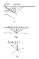
- the reflected waves return to the free surface and are detected by a plurality of receivers located along a seismic line or at grid points (Fig. 1). These receivers transform the seismic oscillations into electrical signals which are suitable for later processing. This technique is called "reflecting shooting".
- the main object of data processing in reflecting shooting is to select useful reflected waves (primaries) carrying information about deep sub-surface structures, and to suppress unwanted signals (multiples. refracted, surface and other types of waves) and noise.
- CDP Common Depth Point
- the seismic data in the CDP method is generated and collected by source-receiver pairs via ray paths shown in Fig. 2.
- the midpoint between source and receivers is labeled Ao.
- the positions of a source and a receiver corresponding to the one trace (pair) are labeled Ak and Ak-.
- Their coordinates X. and X- k are determined by the relationship: Thus all pairs Ak * and Ak- have the same middle point; therefore the CDP method is also called the Common Middle Point (CMP) method.
- CMP Common Middle Point
- the display of seismic traces associated with the CDP configuration of source-receiver pairs is called the CDP (or CMP) gather, or the CDP seismogram. Summing (or stacking) of traces of a CDP gather is based to the CDP method.
- the static correction is to compensate for the irregularities in reflection arrival times resulting from near surface variation in elevation, weathering thickness, and weathering velocity.
- the object of the static correction is to reduce each trace to a "flat" reference (datum) level without the weathering zone.
- the dynamic correction is a time-device correction which is needed because of the existence of a difference ATk of reflection arrival times at the (k-th) trace and of the predetermined central (zero offset) trace.
- the value ⁇ Tk is called a Normal Moveout (NMO) and can be computed with the help of the following approximate relationship: where where Vs(to) is a so-called stacking velocity for zero time to. If values of Vs are correctly selected, the NMO correction puts all primary reflections on traces of a CDP gather in phase; after this, all traces of a CDP gather are stacked. Thus, one output trace, called a stacked trace, is obtained for each middle point Ao. In many cases primaries on an optimal stacked trace are enhanced against unwanted waves and noise.
- a stacked section, called a time section can be obtained by repeating the stack for a sequence of middle points and plotting the obtained CDP stacked traces u(xo,to) as a two-dimentional function of middle point coordinate xo and the half two-way zero time to.
- the time section is an image of a subsurface structure, but it is a distorted image because reflections from dipping and curveo interfaces actually come not from directly under the halfway position as plotted. To remove this distortion a special, technique called migration, is applied to time sections.
- a method of analysing the structure of a medium by means of waves reflected by inner interfaces comprising:
- the method is particularly applicable for seismic prospecting, whereupon the recorded traces would be seismic traces.
- the invention could also be used for tomographic or non-destructive testing of a body, whereupon the recorded traces would be reflected sonic waves applied to the tested body.
- the method includes the further step, following step (c), of producing an image of the common reflecting point having coordinates depending on the parameters r o and So of the optimal oblique spherical correction, step (d) producing an image of the inner interfaces.
- step (a) is performed by distributing the source-receiver pairs in the field according to the given optimal quasi-focusing distribution, and step (b) is performed according to the given optimal oblique spherical correction.
- steps (a) and (b) are performed by distributing the source-receivers pairs in the field according to an arbitrary distribution, and under the conditions that the parameters of the optimal quasi-focusing distribution and the optimal oblique spherical correction are given; and a plurality of optimally quasi-focusingly distributed and optical corrected synthetic traces, called an optimal corrected quasi-focusing gather, are generated from the said field data by:
- steps (a), (b) and (c) are performed by distributing source-receiver pairs in the field according to arbitrary distributions and under conditions that the parameters of the optimal quasi-focusing distributions and of the optimal dynamic correction are not known; and the optimal corrected quasi-focusing gather is generated from the said field data.
- the predetermined zero-offset record becomes a center trace of a fixed number of immediately adjacent traces.
- the distances of a source and a receiver of the k-th pair (trace) corresponding to the quasi-focusing distributions are determined by the two following associated polynomial distributions: where k is a number of a seismic trace (source-receiver pair ), K is the number of the seismic traces, OX is the offset of one of the pair on a long arm of an arrangement (spread), ⁇ X k is the offset of the other of the pair on a short arm, am is a given polynomial coefficient. N is a given order of the polynomial, y k is an independent variable, which takes values from a given sequence of numbers (e.g,, for discrete set y k 0,1,...K-1).
- the field or synthetic seismic traces of a multiple coverage system of observation are generated according to a given arbitrary distribution of one of the source-receiver pair along a long arm and according to the following quasi-focusing distribution of the other of the pair along a short arm: where y K is a root of the following polynomial equation where is a number from the given arbitrary distribution of offsets along a large arm.
- the field or synthetic seismic traces of a multiple coverage system of observation are generated according to a given arbitrary distribution of one of the source-receiver pair along a large arm and according to the following quasi-focusing distribution of the other of the pair along of the short arm where is a number from the given arbitrary distribution.
- ⁇ K is a difference of arrival time of wave coming to the K-th trace and to the central trace; ro is, as earlier, the radius of curvature of wavefront emitted by the fictitious source located at the CRP and coming to the central point at an angle ⁇ o, and Vo is a velocity of wave propagation near the reference level.
- Oblique Spherical Correction This form of a dynamic correction is called the Oblique Spherical Correction (OSC) because it is obtained under assumption that the said wavefront is a spherical one with the radius of curvature ro, of wavefront coming at the predetermined central point at an angle po.
- the Oblique Spherical Correction is determined by the following relationship: which could be reduced to the expression where
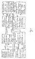
- Fig. 5 the block-diagram for the Common Reflecting Element Section Construction is shown.
- the seismic traces recorded in the field by the quasi-focusingly distributed source-receiver pairs 1 and their coordinate (values of offsets and the coordinate of the central point) are sent to block 3 and 2 respectively.
- the corrected trace U(t-A Tk , , )-U k (t- ⁇ k ) is sent in the summator 6 for the stack.
- the envelope a(to) of the stacked trace M(t o ) are also determined.
- the stacked trace and their envelope are sent in the storage 7.
- the coordinates of the central points and corresponding parameters at the Oblique Spherical Correction are stored
- the found values ro and ⁇ o can be used for determination of Cartesian coordinates X and 2 of the point image C o of the Common Reflecting Point, corresponding to the predetermined central points Ao(xo) with help of the relationship (block 7)
- a plurality of envelopes a are determined. Some of found envelopes could have the same arguments x ⁇ u ⁇ , in this case the total amplitude a (x.z) in the image point ⁇
- X ⁇ . ⁇ ) is a sum of all envelops a(x ⁇ . ⁇ ) having the same arguments x and ⁇ .
- the determined values of radii ro and of angles of entry ⁇ o for a plurality of determined central points can also be used as input data for migration of stacked fields to their real positions in a medium.
- an optimal corrected quasi-focusing gather is generated in the following way as illustrated in Fig. 6.
- ) are determined. Then the given coordinates and the three found coordinates ⁇ X 1 . ⁇ X N 1 . ⁇ X N1+1 from block 4, the given value of the angle of entry ⁇ o , and the radius of the wavefront curvature ro from the job-input 3b and 3c, are sent in the computer 5 for determination of three values ⁇ 1 , ⁇ N1 , and ⁇ T N1-1 of the Oblique Spherical Correction according to the given above-given expressions for three neighbouring pairs and and ⁇ X N , and and ⁇ X N1+1 .
- a pair of recorded traces U(t ⁇ X + . ⁇ X N 1 ) and U(t, , ⁇ X N 1+1 ) from storage device 2 and the found values ⁇ N1 and ⁇ N1+1 ,., from the computer 5 are sent to device 6 for the time delay and for obtaining the time-shifted traces:
- the corrected synthetic trace U(t-Ati, ⁇ x 1 + ⁇ x 1 - ) corresponds to a given value ⁇ X 1 + from arbitrary distribute coordinates AXk of one of the source- receiver pairs along a long arm, (2) to the found value ⁇ X 1 - of a coordinate of the other of the pair from binomial (polynomial) root distribution with the given value (values) a of the asy-factor (factors), and (3) to the found value A T1 of the Oblique Spherical Correction with the given value ⁇ o and ro.
- This corrected synthetic trace from the summator 7 is sent to the storage device 8.
- the third embodiment of the invention is intended for the situations encountered most frequently in the practice, while a plurality of seismic traces are recorded in the field according to given arbitrary distributions and the parameters of the optimal quasi-focusing distributions of source and receiverz and of the optimal Oblique Spherical Correction are unknown. Only sets of possible values of this parameter are known.
- Fig. 7 illustrates the method of generation of the optimal corrected quasi-focusing gather under these conditions.
- the field recorded traces U(t, , , and arbitrary distributed coordinates and of corresponding sources and receivers from the storages devices 2 and 1 are sent to block 4, which was described before (Fig. 6), for generation of the traces U(t, , , ⁇ , ⁇ o , r o ) with fixed values of parameter ⁇ , ⁇ o and ro from the given sets of its possible values.
- These values of a, ⁇ o and ro are sent to block 4 from the job-input devices 3a, 3b and 3c.
- the outputs from the block 4 are the synthetic traces (t- ⁇ ⁇ k , , , ⁇ , ⁇ o ,r o ) of the corrected quasi-focusing gather, which are sent to block 5 for measurement of some chosen coherence criterion.
- the semblance or Student's criterion or cross- correlation function, or another known or newly invented criterion, W(t, ⁇ , ⁇ o ,r o ) could be chosen, as a measure of coherence between the traces of the generated in block 4 corrected quasi-focusing gather with the fixed values of the parameters ⁇ , ⁇ o and ro.
- the output from block 5 is a function W(to, ⁇ , ⁇ o,ro) of zero time to, which gives a value of the coherence measure for fixed values of the parameters a, ⁇ o and ro, received by block 5 from blocks 3a. 3b and 3c.
- W(to, ⁇ , ⁇ o,ro) of zero time to which gives a value of the coherence measure for fixed values of the parameters a, ⁇ o and ro, received by block 5 from blocks 3a. 3b and 3c.
- the traces W(to, ⁇ , ⁇ o , ro) and M(to, ⁇ , ⁇ o, ro) are sent to the optimizer 6.
- the last sends a signal to blocks 1, 2 and 3 to repeat a cycle of the determination of the second function W (1) (to. ⁇ (1) , ⁇ o (1) - ,ro (1) ) corresponding to other combination of the fixed values ⁇ (1) , ⁇ o (1 ) and ro (1) .
- the five traces W(to), M(to), ⁇ (to), ⁇ (to) and r ⁇ o(to) remain in the optimizer 6, which sends a signal to blocks 1, 2 and 3 to repeat determination of a coherence measure W(to) and stacked field M(to) for another combination of fixed parameters ⁇ , ⁇ o,and ro.
- the trace W (1) (to) has been compared with the optimized before trace and the new optimized trace W(to) and the new corresponding stacked field M ⁇ (to)
- the parameters ⁇ (to), ⁇ o(to) and r ⁇ o(to) have been found, the cycle is repeated until all combinations of the given possible values of the parameters a , ⁇ o and ro have been tested.
- the output from the optimizer 6 after performing all of the cycles is the five traces W(to), M ⁇ (to), ⁇ (to), do(to) and ro(to), which are the maximum value of coherence measure module and the corresponding values of the stacked field and of the parameters at each moment of zero time.
- step (d) of the general scheme of the method The found optimal corrected quasi-focusing gather with the asy-factor a(to) and the OSC with the angle of entry ⁇ o(to) and the radius of wavefront curvature r ⁇ o(to) is used in step (d) of the general scheme of the method.
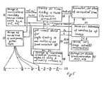
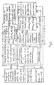
- source-receiver pairs are disposed on a free surface in this way, that all specular points for all rays pairs coincide with the point of reflection Co for ray normally incident to the reflector and corresponding to the central point Ao of spread.
- An angle of reflection is equal an angle of incidence for each arriving ray (Snell's low). Since Snell's low is used in construction of depicted rays diagram, it actually means that a leading part of contributions to a field of a wave reflected at the CRP and recorded at points Ak-, come from an element dS of a reflector S. comparable with the Fresnel zone. In other words, a wave reflects not only at the point Co, but by a some element dS of a surface S surrounding the CRP.
- the front E of a wave emitted by a fictitious source at point Co and coming at the central point Ao in the half zero time to '2 is depicted in Figs. 8b and 8c.
- the center of this emitted front is at the point ⁇ o.
- the wave front E could be approximately considered as a spherical one in some a neighbourhood of the central point Ao. In this approximation, the centre of wavefront curvature could be considered as an imaginary source.
- the rays of wave coming from this imaginary source ⁇ o to the points Ax * and Ax- are shown in Fig. 8c by the dotted lines.
- source offsets are positive (as in Fig. 8).
- am depends on the structure of the overburden and the geometry of the normal central ray CoAo.
- the degree of asymmetry of distributions and with respect to the central point Ao depends on the values of each of coefficient am, thus, am is called the factor of asymmetry of m-th order. or in short, the asy-factor of the m-th order.
- ro is the radius of curvature of the wavefront emitted by a fictitious source located on the reflector at the Common Reflecting Point and coming to the central point Ao at an angle of entry ⁇ o (Fig. 8b);
- Lo and Lo are the so-called 2D spreading function which characterizes the divergence of rays coming to the central point Ao; and its derivative with respect to the angle of incidence
- Oblique Spherical Correction is determined by one of the following equivalent relationships where
- y k is not an independent variable.
- the offsets ⁇ X + k of one of the source-receiver pairs are distributed along a large arm according to an arbitrary (for example, uniform) distribution. Then the offsets of the other of the source-receiver pairs are distributed along a short arm according to the so-called polynomial root distribution where YK is the root of the following polynomial equation where is a given offset along a large arm.
- the offsets of one of the source-receiver pairs are distributed along the large arm according to an arbitrary distribution; the corresponding offsets on the short arm are distributed according to the so-called binomial root distribution:
- the block diagram of the general scheme of the invention is shown in Fig. 5.
- the multiple coverage data represented by a plurality of recorded seismic traces, corresponding to a plurality of the source-receiver pairs, are distributed in the field according to the one plair of the said above (associated polynomial [binomial] or arbitrary-root polynomial [binomial]) distributions.
- the recorded traces and coordinates of the sources and receivers and corresponding to each recorded traces are sent to the storages devices 3 and 2 respectively.
- a plurality of records corresponding to the predetermined central point contains twelve seismic traces.
- Each recorded trace U k (t) from block 3. and the given value of radius of curvature ro of the wavefront emitted by a fictitious source located at the Common Reflecting Point and coming at the central point at a give angle of entry ⁇ o. are generated by the job-input device 4b and 4a, and are sent to device 5 for time delay determined by the Oblique Spherical Correction.
- the corrected trace U k (t o -AT k ) from block 5 is sent to summator 6, which sends a signal to the storage device 3 to send next recorded trace U k+1 (t), until all twelve corrected traces are stored in the summator.
- the stack of traces M(t o )and its envelope a(t o ), also determined in the summator 6, the corresponding parametes ⁇ o and ro of the Oblique Spherical Correction, and the coordinates of the predetermined center points. are sent to the storage devices 9 and 8.
- the coordinate xo o the center point, and parameters ;3 0 and ro from the device 4a and 4b. are also sent to block 7 for determination of the coordinates X and 2 of the image point Co.
- the values x and 2, and' the envelope a(t) from block 6, are sent to the display for image section construction after repetitions of cycles for a plurality of the central points.
- each reflecting interface is a locus of the centers of curvature of the wavefronts emitted by the fictitious sources located at the Common Reflecting Points, which are points of intersection of normal rays. leaving the central points, with the reflecting interface.
- the values from block 7 and 8 can be sent for subsequent data processing, e.g., for interval velocity estimation and migration.
- the second method it is assumed that the values of the parameters of the optimal quasi-focusing distributions (the asy- factor am or simply a), and of the Oblique Spherical Correction, are given.
- the object of the second method to generate so-called the optimal corrected quasi-focusing gather i.e., a plurality of the synthetic seismic traces, corresponding to the given optimal quasi-focusing distributions of the source-receiver pairs and optimally corrected according to the given Oblique Spherical Correction.
- a plurality of the recorded seismic traces, corresponding to arbitrary distributions of sources and receivers, and corresponding coordinates of sources and receivers, are stored in the blocks 2 and 1.
- the 144 recorded traces and twelve pairs of coordinates of source-receivers are stored in blocks 2 and 1.
- the value of the asy-factor, and which arm is the larger one, are given.
- the first given coordinate on the large arm from the storage device 1, and the given value of the asy-factor ⁇ from the job-input device 3a are sent to device 4 for determination of the corresponding coordinate on the short arm according to the above-described expressions for the binomial quasi-focusing distribution.
- a pair of recorded traces U(t, ⁇ X 1 + ,OX N 1 ) and U(t, ⁇ X 1 +1) (for considered example, U(t,200,0) and U(t,200,200)) from the storage device 2 and the found values ⁇ N1 and ⁇ N1 +, (for considered example, 0.001 and 0.008 ) from the computer 5 are sent to device 6 for time shift and for obtaining the time corrected traces U(t o ⁇ N1 , 1 ⁇ X N - 1 and U-(t o ⁇ N1 +1 , ⁇ X N 1 + 1 ) (for considered examples U(t- 0.001;200,0) and U-(t o 0.008:200,200).
- the corrected synthetic trace U(t o ⁇ ⁇ 1 , ⁇ X ⁇ corresponds to a given value ⁇ X 1 + (200m) of the given arbitrary distributed coordinates on the large arm and to a found value (180m) of the binominal root distribution on the short arm with a given value of the asy factor ⁇ (0,61) and to the found value ⁇ ⁇ 1 (0.005s) of the OSC with given values ⁇ o and ro.
- This synthetic trace from the summator 7 is sent in the storage device 8.
- the whole cycle of generating the corrected synthetic traces U(t ⁇ ⁇ k , is repeated with the same fixed given values of a, ⁇ o and ro, until all (K-1) corrected synthetic traces and recorded zero-offset trace U(t o ,0,0), corresponding to the optimal corrected quasi-focusing gather, are generated and placed in the storage device 8.
- the given parameters a, ⁇ o and ro are stored in blocks 9.
- the parameter of the optimal quasi-focusing distributions of source and receiver, and of the Optimal Oblique Spherical Correction are unknown, only the regions of possible values of its parameters known beforehand, i.e., the sets of possible values of a, ⁇ o and ro could be given.
- the object of the third method is to determine the optimal corrected quasi-focusing gather from multiple coverage data represented by a plurality of recorded seismic traces corresponding to a plurality of source-receiver pairs, distributed in the field according to arbitrary distributions. while sets of possible values of the parameters of the optimal binomial (polynomial) distribution and of the optimal Oblique Spherical Correction are given.
- Fig. 9 illustrates the normalized stacking chart.
- the dotted vertical (horizontal) straight lines correspond to the Common Source (Receiver) Point configurations or vice versa.
- the intersection of each vertical (horizontal) line with horizontal (vertical) side of the observation square determines the normalized coordinate of a source (receiver).
- the solid straight line, inclined at the angle ⁇ /4 corresponds to the Common Middle Point configuration.
- Each solid curved line corresponds to the binomial or binomial root configuration of source-receiver pairs with the fixed value of the asy-factor. It is convenient for a stacking chart consideration to use, instead of the asy-factor as a parameter of a binomial distribution. the other parameter.
- Fig. 10 illustrates the scheme explaining the operation of the second method.
- the solid lines determine the given quasi-focusing configuration of the source-receiver pairs with a large left arm with a and fixed value of the sy-factor ⁇ equal to 0.4.
- the dotted vertical lines correspond to the 12 Common Source Points recoding configuration.
- the cross located on this line show the position of the source-receiver pairs (traces) used by generating the synthetic traces.
- the weighed summation of two corrected recorded traces corresponds to procedure of interpolation of two corrected recorded retraces with positions of a source-receiver pair shown by two corresponding cycles located on the same vertical line as the considered cross.
- Fig. 7 illustrates the scheme for the third method.
- the sets of the possible values of parameters of the quasi-focusing distribution and of the Oblique Spherical Correction are given.
- the recorded traces U-(t, ), their offsets AXk and ⁇ X l from the blocks 2 and 1, and the fixed combination of the parameter a. ⁇ o and ro, produced by the job-input device 3, 3b and 3c from the given sets of this parameter. are sent to the block 4 which generates the sythetic traces of the corrected quasi-focusing gather with the said combination of values a, ⁇ o and ro, in accordance with the Fig. 6 diagram.
- the output of block 4, namely the traces U(t ? ⁇ k ; ⁇ X + k ⁇ , ⁇ o,ro) of the corrected binomial gather. are sent to block 5 for measurement of some chosen coherence criterion (measure).
- the semblance or Student's criterion, or cross correlation function, or other known or newly invented criterion W(t o ; ⁇ , ⁇ ,r) could be used as a measure of coherence between the synthetic traces of the corrected binomial (polynomial) gather with fixed values of the parameters a, ⁇ o and ro.
- the output from block 5 is a function W(to, ⁇ , ⁇ o,ro ) of zero time to, which gives a value of the chosen measure of coherence for the fixed values a, ⁇ o and ro.
- the stacked trace M(t) is also outputted from block 5.
- the traces W(t o , ⁇ , ⁇ o ,r o ) and M(t) and values of a, ⁇ o and ro are sent to the optimizer 6.
- a signal is sent to blocks 1, 2 and 3 to repeat a new cycle for determining the second function W (1) (t o ; ⁇ (1) . ⁇ o (1)- r o (1 ), corresponding to other combination of fixed values ⁇ (1) , ⁇ o (1) and r o (1) of the parameters of the binomial distribution and of the OSC.
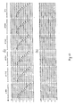
- Figs. 12 and 13 illustrate the results of testing the principal blocks of the above-described methods.
- the model of the medium for which the theoretical seismograms was calculated is shown in Fig. 12.
- the fields of reflected waves were computed for the Common Short Point configurations with the twelve-fold coverage length of each speed ⁇ X ax is equal to 11.
- the predetermined central point A o has the coordinate Xo equal to 20.
- the radius ro is equal to 10.3
- an angle of entry ⁇ o is equal to 29.7 ⁇ .
- the twelve CSP gathers (or 144 recorded traces) was placed in storage device 2 (Fig. 7).
- the sets for possible values of parameters of the binomial root distribution and the OSC are as follows:
Landscapes
- Engineering & Computer Science (AREA)
- Remote Sensing (AREA)
- Physics & Mathematics (AREA)
- Life Sciences & Earth Sciences (AREA)
- Acoustics & Sound (AREA)
- Environmental & Geological Engineering (AREA)
- Geology (AREA)
- General Life Sciences & Earth Sciences (AREA)
- General Physics & Mathematics (AREA)
- Geophysics (AREA)
- Geophysics And Detection Of Objects (AREA)
Applications Claiming Priority (2)
| Application Number | Priority Date | Filing Date | Title |
|---|---|---|---|
| IL83306 | 1987-07-23 | ||
| IL83306A IL83306A (en) | 1987-07-23 | 1987-07-23 | Method of analysing the structure of a medium,particularly useful for seismic prospecting |
Publications (2)
| Publication Number | Publication Date |
|---|---|
| EP0300477A2 true EP0300477A2 (de) | 1989-01-25 |
| EP0300477A3 EP0300477A3 (de) | 1990-07-11 |
Family
ID=11058012
Family Applications (1)
| Application Number | Title | Priority Date | Filing Date |
|---|---|---|---|
| EP88111767A Withdrawn EP0300477A3 (de) | 1987-07-23 | 1988-07-21 | Verfahren zur Mediumstrukturanalyse, insbesondere zur Anwendung bei seismischer Prospektion |
Country Status (3)
| Country | Link |
|---|---|
| US (1) | US4878205A (de) |
| EP (1) | EP0300477A3 (de) |
| IL (1) | IL83306A (de) |
Cited By (2)
| Publication number | Priority date | Publication date | Assignee | Title |
|---|---|---|---|---|
| RU2145097C1 (ru) * | 1997-12-02 | 2000-01-27 | Объединенный институт физики Земли им.О.Ю.Шмидта РАН | Способ сейсмической разведки |
| RU2265867C2 (ru) * | 2003-12-29 | 2005-12-10 | Институт геофизики Уральское отделение Российской академии наук (РАН) | Полевая аппаратура и способ сейсмического мониторинга |
Families Citing this family (16)
| Publication number | Priority date | Publication date | Assignee | Title |
|---|---|---|---|---|
| US5138584A (en) * | 1989-09-06 | 1992-08-11 | Chevron Research & Technology Company | Migration of seismic turning waves |
| IL92132A (en) * | 1989-10-27 | 1994-07-31 | Gelchinsky Boris | Homeomorphic character method for analyzing the structure of the medium |
| FR2675590B1 (fr) * | 1991-04-19 | 1993-07-16 | Elf Aquitaine | Procede de traitement pour l'obtention d'une section somme a offsets nuls. |
| US5269309A (en) * | 1991-12-11 | 1993-12-14 | Fort J Robert | Synthetic aperture ultrasound imaging system |
| US5450370A (en) * | 1993-05-28 | 1995-09-12 | Western Atlas International, Inc. | Quality assurance of spatial sampling for DMO |
| DE19619641C1 (de) * | 1996-05-15 | 1997-08-21 | Daimler Benz Ag | Verfahren zum Verhindern des Parkens eines Fahrzeugs mit aktiviertem Wegrollverhinderer und unbetätigter Feststellbremse |
| US6691075B1 (en) * | 1999-03-12 | 2004-02-10 | Exxonmobil Upstream Research Company | Method for modeling seismic acquisition footprints |
| WO2000054074A1 (en) * | 1999-03-12 | 2000-09-14 | Exxonmobil Upstream Research Company | A method for modeling seismic acquisition footprints |
| US6330513B1 (en) * | 1999-04-21 | 2001-12-11 | Noranda Inc. | Prospecting technique |
| US6920084B2 (en) * | 2003-01-15 | 2005-07-19 | Western Geco, L.L.C. | Offset transformation to zero dip that preserves angle of incidence |
| US8209125B2 (en) * | 2007-03-12 | 2012-06-26 | Geomage (2003) Ltd. | Method for identifying and analyzing faults/fractures using reflected and diffracted waves |
| US7630865B2 (en) * | 2007-09-11 | 2009-12-08 | Geomage (2003) Ltd | Complex analysis of kinematics for non-hyperbolic moveout corrections |
| US8209126B2 (en) * | 2008-04-01 | 2012-06-26 | Geo{umlaut over (m)}age (2003) Ltd. | Wavefront-defined Radon transform |
| US8879798B2 (en) | 2011-03-31 | 2014-11-04 | Westerngeco L.L.C. | Frequency-dependent ray tracing through an interface |
| CN109856676B (zh) * | 2018-11-30 | 2021-03-12 | 西南石油大学 | 一种实现地震共反射面叠加参数优化的方法 |
| CN112130203B (zh) * | 2020-08-17 | 2023-11-10 | 中国石油集团东方地球物理勘探有限责任公司 | 地震勘探的激发点和接收点的位置质量确定方法及装置 |
Family Cites Families (6)
| Publication number | Priority date | Publication date | Assignee | Title |
|---|---|---|---|---|
| US3346068A (en) * | 1966-10-20 | 1967-10-10 | Atlantic Richfield Co | Focusing and scanning either or both of a plurality of seismic sources and seismometers to produce an improved seismic record |
| US4330873A (en) * | 1970-07-27 | 1982-05-18 | United Geophysical Corporation | Aplanatic geophysical exploration system |
| DE2247426A1 (de) * | 1971-09-28 | 1973-04-05 | Mobil Oil Corp | Verfahren zum stapeln seismischer spuren |
| US4363113A (en) * | 1975-02-10 | 1982-12-07 | Seiscom Delta, Inc. | Seismic exploration with simulated plane waves |
| US4503527A (en) * | 1981-03-30 | 1985-03-05 | Mobil Oil Corporation | Method for enhancement of the signal-to-noise ratio in seismic reflection signals |
| US4742497A (en) * | 1985-11-18 | 1988-05-03 | Western Atlas International, Inc. | Method of processing seismic data |
-
1987
- 1987-07-23 IL IL83306A patent/IL83306A/xx not_active IP Right Cessation
-
1988
- 1988-07-11 US US07/217,269 patent/US4878205A/en not_active Expired - Fee Related
- 1988-07-21 EP EP88111767A patent/EP0300477A3/de not_active Withdrawn
Cited By (2)
| Publication number | Priority date | Publication date | Assignee | Title |
|---|---|---|---|---|
| RU2145097C1 (ru) * | 1997-12-02 | 2000-01-27 | Объединенный институт физики Земли им.О.Ю.Шмидта РАН | Способ сейсмической разведки |
| RU2265867C2 (ru) * | 2003-12-29 | 2005-12-10 | Институт геофизики Уральское отделение Российской академии наук (РАН) | Полевая аппаратура и способ сейсмического мониторинга |
Also Published As
| Publication number | Publication date |
|---|---|
| US4878205A (en) | 1989-10-31 |
| IL83306A0 (en) | 1987-12-31 |
| IL83306A (en) | 1990-12-23 |
| EP0300477A3 (de) | 1990-07-11 |
Similar Documents
| Publication | Publication Date | Title |
|---|---|---|
| EP0300477A2 (de) | Verfahren zur Mediumstrukturanalyse, insbesondere zur Anwendung bei seismischer Prospektion | |
| Kisslinger et al. | Procedures for computing focal mechanisms from local (SV/P) z data | |
| EP0117280B1 (de) | Vertikale seismische Erforschung | |
| EP0202745B1 (de) | Verfahren zur Moveout-Korrektion und Abschätzung der Sammlungsgeschwindigkheit für ausgelegte vertikale seismische Profildaten | |
| US5173880A (en) | Method of generating seismic wavelets using seismic range equation | |
| US6826484B2 (en) | 3D prestack time migration method | |
| US4839869A (en) | Methods for processing converted wave seismic data | |
| US4611311A (en) | Method of seismic processing involving converted P- or S-wave data | |
| US4597066A (en) | Method of seismic processing and displaying simultaneously collected conventional and converted P- or S-wave data | |
| CA1330235C (en) | Method for processing seismic data | |
| EP0206457A2 (de) | Verfahren zum Absondern und Ansammeln von vertikalen seismischen Profildaten | |
| US5103429A (en) | Homeomorphical imaging method of analyzing the structure of a medium | |
| US20030187583A1 (en) | Method and apparatus for resolving shear wave seismic data | |
| US20080170468A1 (en) | Method for Processing at Least Two Sets of Seismic Data | |
| US5515335A (en) | Seismic trace overburden correction method | |
| US8139441B2 (en) | Method for bispectral picking of anelliptical NMO correction parameters | |
| US6584409B2 (en) | Seismic processing method to improve spatial resolution | |
| US6430508B1 (en) | Transfer function method of seismic signal processing and exploration | |
| US8144543B2 (en) | Seismic data processing method for RMO picking | |
| US4918670A (en) | Method for interval velocity analysis and determination of reflector position from before stack seismic data | |
| US4847813A (en) | Method for extending the lateral subsurface coverage in VSP surveys | |
| Dahl et al. | NON‐LINEAR AVO INVERSION FOR A STACK OF ANELASTIC LAYERS1 | |
| Vesnaver | Ray tracing based on Fermat's principle in irregular grids1 | |
| US6131070A (en) | Method of generating a fold distribution and of evaluating a seismic survey | |
| Neidell | Sampling 3-D seismic surveys: A conjecture favoring coarser but higher-fold sampling |
Legal Events
| Date | Code | Title | Description |
|---|---|---|---|
| PUAI | Public reference made under article 153(3) epc to a published international application that has entered the european phase |
Free format text: ORIGINAL CODE: 0009012 |
|
| AK | Designated contracting states |
Kind code of ref document: A2 Designated state(s): DE FR GB NL |
|
| PUAL | Search report despatched |
Free format text: ORIGINAL CODE: 0009013 |
|
| AK | Designated contracting states |
Kind code of ref document: A3 Designated state(s): DE FR GB NL |
|
| 17P | Request for examination filed |
Effective date: 19901217 |
|
| 17Q | First examination report despatched |
Effective date: 19910729 |
|
| STAA | Information on the status of an ep patent application or granted ep patent |
Free format text: STATUS: THE APPLICATION IS DEEMED TO BE WITHDRAWN |
|
| 18D | Application deemed to be withdrawn |
Effective date: 19930824 |