EP0300502A2 - Steuersystem zum Umdrehen von Seiten mit grosser Geschwindigkeit - Google Patents
Steuersystem zum Umdrehen von Seiten mit grosser Geschwindigkeit Download PDFInfo
- Publication number
- EP0300502A2 EP0300502A2 EP88111871A EP88111871A EP0300502A2 EP 0300502 A2 EP0300502 A2 EP 0300502A2 EP 88111871 A EP88111871 A EP 88111871A EP 88111871 A EP88111871 A EP 88111871A EP 0300502 A2 EP0300502 A2 EP 0300502A2
- Authority
- EP
- European Patent Office
- Prior art keywords
- page
- turning
- window
- display
- image information
- Prior art date
- Legal status (The legal status is an assumption and is not a legal conclusion. Google has not performed a legal analysis and makes no representation as to the accuracy of the status listed.)
- Granted
Links
- 238000000034 method Methods 0.000 abstract description 16
- 238000013507 mapping Methods 0.000 abstract description 6
- 230000006835 compression Effects 0.000 abstract description 5
- 238000007906 compression Methods 0.000 abstract description 5
- 230000008569 process Effects 0.000 abstract description 5
- 230000004075 alteration Effects 0.000 abstract description 2
- 230000008901 benefit Effects 0.000 abstract description 2
- 230000006870 function Effects 0.000 description 16
- 230000000694 effects Effects 0.000 description 7
- 238000010586 diagram Methods 0.000 description 6
- 238000012546 transfer Methods 0.000 description 5
- 238000010276 construction Methods 0.000 description 3
- 230000008602 contraction Effects 0.000 description 2
- 238000012986 modification Methods 0.000 description 2
- 230000004048 modification Effects 0.000 description 2
- 238000012545 processing Methods 0.000 description 1
- 230000002311 subsequent effect Effects 0.000 description 1
- 238000013519 translation Methods 0.000 description 1
Images



Classifications
-
- G—PHYSICS
- G09—EDUCATION; CRYPTOGRAPHY; DISPLAY; ADVERTISING; SEALS
- G09G—ARRANGEMENTS OR CIRCUITS FOR CONTROL OF INDICATING DEVICES USING STATIC MEANS TO PRESENT VARIABLE INFORMATION
- G09G5/00—Control arrangements or circuits for visual indicators common to cathode-ray tube indicators and other visual indicators
- G09G5/14—Display of multiple viewports
Definitions
- the present invention generally relates to an image display system and more particularly, to a high speed page turning control system based on a hardware window type.
- the control system based on a raster operation as shown in Fig. 5(a) is of a software window type so arranged that each image information of windows A, B and C stored in a window memory 1 is once subjected to block transfer to a display memory 2, on which editing of the image surface such as positioning, overlapping, etc. for the respective windows A, B and C is effected, and thereafter, the image information is successively read out from the display memory 2 for displaying multi-windows on a CRT (cathode ray tube) 3.
- a CRT cathode ray tube
- each image information of windows A, B and C is stored in a window memory 4 and the address of the image information corresponding to the scanning position of a CRT 6 is outputted during scanning of the CRT 6 through successivelysive change-over from a mapping table 5 in the form of a hardware, whereby the image information from the window memory 4 is read by time division according to said address so as to display the multi-windows directly on the CRT 6 without passing through any other memory.
- control system based on clipping as shown in Fig. 5(c) is of a software window type so arranged that code data representing the image information for the windows A, B and C as stored in a segment buffer 7 is displayed on a display memory 8, with the code data of the image information outside the windows being removed by clipping, and thus, the image information is successively read out from the display memory 8 for displaying multi-windows on the CRT 9.
- an essential object of the present invention is to provide a high speed page turning control system which is capable of representing the page turning process by actively displaying the image of compressed windows through alternation of parameters showing the window regions following the window compression per each frame refreshing by utilizing the high speed characteristic which is the advantage in the hardware window system based on the mapping table.
- Another object of the present invention is to provide a high speed page turning control system of the above described type, which is simple in construction and accurate in functioning at high reliability.
- a high speed page turning control system which includes a window buffer memory for storing image information such as sentences, drawings, tables, etc. to be displayed on a display device, a display priority order setting means for setting priority order of display, during display of a rectangular region for turning page and that for stationary page on said display device, a turning amount calculating means for successively calculating size of the rectangular region of the turning page to be displayed on said display device, a thinning-out amount calculating means for successively calculating the thinning-out amount of the image information for the turning page according to the size of the rectangular region as calculated by said turning amount calculating means, and a controller for directly displaying the images for the turning page and stationary page on the display device successively, by controlling reading position of the image information for the turning page and that for the stationary page stored in said window buffer memory, according to the display priority order set by said display priority order setting means, the size of the rectangular region for the turning page as calculated by said turning amount
- the size of the rectangular region of the turning page to be displayed on the display device is successively calculated by the turning amount calculating means, and the thinning-out amount of the image information for the turning page is also successively calculated according to the size of the rectangular region as calculated by the turning amount calculating means.
- the size of the rectangular region for the turning page as calculated by said turning amount calculating means, and the thinning-out amount for the turning page image information as calculated by said thinning-out amount calculating means are successively controlled by the controller to read out the image information, and the images for the turning page and stationary page are directly displayed on the display device successively. Accordingly, the image in which the rectangular region of the turning page is compressed may be displayed actively.
- a window buffer memory 11 commonly serving as a main memory and coupled with the CPU (central processing unit) 14 and a graphic controller 12 through a bus line 16, and also to a CRT (cathode ray tube) 15 through a window controller 13 as shown.
- the window buffer memory 11 is a memory for storing image information such as sentences, drawings, tables, etc., and also serves as the main memory in the present embodiment for achieving efficient utilization of the memory.
- access of the CPU 14 to the main memory is required to wait during access from the graphic controller 12 to the window buffer memory 11, it becomes possible to effectively utilize the window buffer memory 11 whose capacity is increased with the increase of the information capacity of the image to be displayed.
- the graphic controller 12 effects the graphic drawing, etc. to the window buffer memory 11 through the bus line 16.
- the window controller 13 is a controller for displaying the contents of the window buffer memory 11 directly onto the CRT 15 without passing through any other memory, by controlling the image information reading address of the window buffer memory 11 in order to realize a real page turning. Such control of the reading address, etc. may be effected by writing parameters related to the display, into a register in the window controller 13.
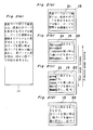
- the term "active page turning” indicates the display function as follows. Specifically, windows of the same size, i.e. the window for displaying the first page 21 and the window for displaying a second page 22 are overlapped, and the size of the window for the turning page in the horizontal direction is altered so as to display therein the image of the turning page as compressed.
- the window for the first page 21 in Fig. 2(a) is compressed leftwards in the drawing (i.e. the window of the first page 21 is narrowed in its width, and the image information for the first page 21 as thinned-out is displayed in said narrowed window), part of the right side for the second page 22 (i.e. the sentence " ....
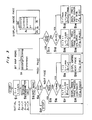
- Fig. 3 shows a flow-chart for the page turning control routine of a document. Subsequently, the page turning control function according to the present invention will be described hereinbelow with reference to Figs. 2 and 3.
- symbols lx, ly, lv and lh represent parameters for designating regions of the window, while a symbol L denotes a width of an image surface on the window buffer memory 11.
- the data of the window buffer memory 11 may be thinned out in the horizontal direction on the image surface of the CRT 15.
- Symbols L min and L max are the minimum and maximum values of the image surface width L on the above memory, and determined by the hardware of the window processor respectively, while a symbol T is a contraction ratio. It is also assumed that the display priority order for the window with a smaller number of pages is set to be high by a display priority order setting means.
- step S3 key input for the page turning function designation is effected.
- step S4 check for the key inputted at above step S3 is made.
- the procedure proceeds to step S5
- step S11 if it is of a previous page turning function, the procedure proceeds to step S11, and if it is of a page turning stopping, the procedure proceeds to step S17 to complete the control routine.
- step S5 it is judged whether or not the page displayed on the CRT 15 is of a last page. As a result of the judgement, if the page is of the last page, the procedure is returned to step S3 on the assumption that the next page turning function has been completed. If the page is not of the last page, the procedure proceeds to step S6.
- Step S6 it is checked whether or not L is larger than L max. As a result, if L is larger than L max, the procedure proceeds to step S9 to effect the entire next page display, and if L is not larger than L max, the procedure proceeds to Step S7 for the next page turning display.
- step S8 based on L and lh as calculated at step S7, the first page as shown in Fig. 2(a) is contracted to 1/2, and as shown in Fig. 2(b), the image in which the first page 21 is half turned, is displayed in the manner as described below, and thus, the step is returned to step S3.
- the value LH of the window parameter lh for the turning page stored in the register for the turning page (here, the first page 21) within the window controller 13 in Fig. 1 is replaced by LH/2 as calculated at the above step S7.
- the window controller 13 is arranged to access by thinning out every other address of the image information for the turning page within the window buffer memory 11.
- the window parameter lh in the register for the stationary page (here, the second page 22) of the window controller 13 remains to be LH.
- the portion 21 on the CRT 15 where the turning page window and the stationary page window are adjacent to each other i.e.
- the image information for the first page with the higher display priority order is read out as being thinned out at every other portion in the horizontal direction on the image surface of the CRT 15 through control by the window controller 13, so as to be directly displayed on the CRT 15 without passing through any other memory, whereby the image for the first page contracted to 1/2 in the horizontal direction, is displayed thereon.
- the window 22 only for the stationary page (at the right side half on the image surface), in the image for the second page which is not contracted, only the portion not overlapped with the image of the first page is displayed. As a result, the state where the turning page is turned only by half is displayed.
- steps S3 to S8 are repeated until the relation becomes L > L max.
- step S10 as shown in Fig. 2(d), only the next page (the second page 22) is displayed on the entire surface of the window, and the next page turning function equivalent to one page is completed.
- step S11 it is checked whether or not the page as displayed on the CRT 15 at present is of a leading page at the head. if it is of a leading page, the procedure returns to step S3 on the assumption that the previous page turning function has been completed, while on the contrary, if it is not of a leading page, the procedure proceeds to step S12.
- step S12 it is checked whether or not L is smaller than L min, and if it is smaller than L min, the procedure proceeds to step S13 to effect the previous page minimum display, while if it is not smaller than L min, the step proceeds to step S15 to effect the previous page turning display.
- T T max
- L L max
- step S14 in the manner as described above, the turning page (here, the first page 21) as compressed to the minimum window width is displayed on the window for the turning page, and in the other window, the uncompressed image of the stationary page (here, the second page 22) is partially displayed (Fig. 2(c)).
- step S16 based on the L and lh as calculated at step S14, the image in which the turning page is further turned as described above is displayed, and then, the procedure returns to step S3.
- steps S3 to S16 are repeated, and the images in which the turning page (previous page) is successively enlarged are displayed as shown in Figs. 2(b) and 2(a).
- only the previous page is displayed on the entire surface of the window as shown in Fig. 2(a), and thus, the previous page turning function equivalent to one page is completed.
- the turning page window is preliminarily set higher, and then, the size of the window for displaying the turning page and the thinning-out amount of the page information of the turning page corresponding to the contraction ratio of the window are successively calculated, and based on the result of this calculation, the reading address of the image information of the window buffer memory 11 is controlled by the window controller for reading out the image information.
- the image if the turning page compressed according to the size of the contracted window for the turning page with the higher display priority order is displayed, while in the other portion, only one portion of the uncompressed stationary page is displayed.
- a high speed page turning may be executed based on the hardware window system arranged to display the image information with the window buffer memory as read out through access by the control of the window controller, directly on the CRT 15 without passing through any other memory.
- FIG. 4 there is shown a block diagram for a high speed page turning control system according to a second embodiment of the present invention, which includes a window buffer memory 11 coupled with a CPU 42 through a bus line, a change-over circuit 43 inserted between the window buffer memory 11 and the bus line, and connected to a window controller 13 coupled with the window buffer memory 11 which is further connected to the display device, and a display memory 41 inserted between the bus line and the display device as illustrated.
- the display memory 41 is a two-port display memory i.e. a bit map memory for display having memory elements each corresponding to picture elements on the display device, and the change-over circuit 43 is arranged to effect selection through change-over between the display mode for displaying the contents of the window buffer memory 11 on the display device, and the drawing mode which does not display the contents thereof on said display device.
- the change-over circuit 43 Through changing-over by the change-over circuit 43, it is possible to effect the change-over between the high speed data transfer between the window buffer memory 11 and the two-port display 41, and the direct display of the contents of the window buffer memory 11.
- the high speed page turning control system of the present invention it is so arranged that according to the display priority order set by said display priority order setting means, the size of the rectangular region for the turning page as calculated by said turning amount calculating means, and the thinning-out amount for the turning page image information as calculated by said thinning-out amount calculating means, the reading position of the image information for the turning page and that for the stationary page stored in said window buffer memory are successively controlled by the controller to read out the image information, and the images for the turning page and stationary page are directly displayed on the display device successively.
- the process for turning the pages can be displayed actively and at high speed by images.
Landscapes
- Engineering & Computer Science (AREA)
- Physics & Mathematics (AREA)
- Computer Hardware Design (AREA)
- General Physics & Mathematics (AREA)
- Theoretical Computer Science (AREA)
- Controls And Circuits For Display Device (AREA)
- Digital Computer Display Output (AREA)
- Information Retrieval, Db Structures And Fs Structures Therefor (AREA)
Applications Claiming Priority (2)
| Application Number | Priority Date | Filing Date | Title |
|---|---|---|---|
| JP184059/87 | 1987-07-22 | ||
| JP62184059A JPS6426221A (en) | 1987-07-22 | 1987-07-22 | Fast page turning control system |
Publications (3)
| Publication Number | Publication Date |
|---|---|
| EP0300502A2 true EP0300502A2 (de) | 1989-01-25 |
| EP0300502A3 EP0300502A3 (en) | 1989-11-29 |
| EP0300502B1 EP0300502B1 (de) | 1994-04-06 |
Family
ID=16146654
Family Applications (1)
| Application Number | Title | Priority Date | Filing Date |
|---|---|---|---|
| EP88111871A Expired - Lifetime EP0300502B1 (de) | 1987-07-22 | 1988-07-22 | Steuersystem zum Umdrehen von Seiten mit grosser Geschwindigkeit |
Country Status (4)
| Country | Link |
|---|---|
| US (1) | US5146555A (de) |
| EP (1) | EP0300502B1 (de) |
| JP (1) | JPS6426221A (de) |
| DE (1) | DE3888891T2 (de) |
Cited By (1)
| Publication number | Priority date | Publication date | Assignee | Title |
|---|---|---|---|---|
| CN112114928A (zh) * | 2020-09-28 | 2020-12-22 | 西安万像电子科技有限公司 | 显示页面的处理方法和装置 |
Families Citing this family (14)
| Publication number | Priority date | Publication date | Assignee | Title |
|---|---|---|---|---|
| JP2784032B2 (ja) * | 1989-04-04 | 1998-08-06 | 株式会社日立製作所 | 画面表示切換方法及び画面表示切換装置 |
| JP3245655B2 (ja) * | 1990-03-05 | 2002-01-15 | インキサイト ソフトウェア インコーポレイテッド | 作業スペースの表示処理方法 |
| JPH04127235A (ja) * | 1990-03-09 | 1992-04-28 | Hitachi Ltd | プログラム表示方法および装置ならびにプログラム生成方法および装置 |
| US5283864A (en) * | 1990-10-30 | 1994-02-01 | Wang Laboratories, Inc. | Computer apparatus and method for graphical flip book |
| US5430839A (en) * | 1991-01-28 | 1995-07-04 | Reach Software | Data entry screen method |
| US5351995A (en) * | 1992-01-29 | 1994-10-04 | Apple Computer, Inc. | Double-sided, reversible electronic paper |
| US5526018A (en) * | 1992-10-02 | 1996-06-11 | Foundation Microsystems, Inc. | Stretching scales for computer documents or drawings |
| US5553277A (en) * | 1992-12-29 | 1996-09-03 | Fujitsu Limited | Image search method for searching and retrieving desired image from memory device |
| US5487145A (en) * | 1993-07-09 | 1996-01-23 | Taligent, Inc. | Method and apparatus for compositing display items which minimizes locked drawing areas |
| US5546529A (en) * | 1994-07-28 | 1996-08-13 | Xerox Corporation | Method and apparatus for visualization of database search results |
| JPH0854998A (ja) * | 1994-07-28 | 1996-02-27 | Xerox Corp | コンピュータ制御ディスプレイシステム |
| US5900876A (en) * | 1995-04-14 | 1999-05-04 | Canon Kabushiki Kaisha | Information processing apparatus and method with display book page turning |
| US5894100A (en) * | 1997-01-10 | 1999-04-13 | Roland Corporation | Electronic musical instrument |
| US20040145603A1 (en) * | 2002-09-27 | 2004-07-29 | Soares Stephen Michael | Online multimedia presentation builder and presentation player |
Family Cites Families (6)
| Publication number | Priority date | Publication date | Assignee | Title |
|---|---|---|---|---|
| JPS59180628A (ja) * | 1983-03-31 | 1984-10-13 | Toshiba Corp | 画像表示装置 |
| US4559533A (en) * | 1983-11-03 | 1985-12-17 | Burroughs Corporation | Method of electronically moving portions of several different images on a CRT screen |
| JPS60134357A (ja) * | 1983-12-21 | 1985-07-17 | Hitachi Ltd | 画像フアイル登録・検索方式 |
| FR2559927B1 (fr) * | 1984-02-20 | 1986-05-16 | Comp Generale Electricite | Circuit cable de gestion de fenetres sur ecran |
| JPH0778718B2 (ja) * | 1985-10-16 | 1995-08-23 | 株式会社日立製作所 | 画像表示装置 |
| US4829453A (en) * | 1987-03-05 | 1989-05-09 | Sharp Kabushiki Kaisha | Apparatus for cataloging and retrieving image data |
-
1987
- 1987-07-22 JP JP62184059A patent/JPS6426221A/ja active Pending
-
1988
- 1988-07-19 US US07/221,350 patent/US5146555A/en not_active Expired - Lifetime
- 1988-07-22 DE DE3888891T patent/DE3888891T2/de not_active Expired - Fee Related
- 1988-07-22 EP EP88111871A patent/EP0300502B1/de not_active Expired - Lifetime
Non-Patent Citations (1)
| Title |
|---|
| IBM TECHNICAL DISCLOSURE BULLETIN, vol. 28, no. 12, May 1986 "Variable CRT Dot Widths from a constant Frequency" pages 5318,5319 * |
Cited By (2)
| Publication number | Priority date | Publication date | Assignee | Title |
|---|---|---|---|---|
| CN112114928A (zh) * | 2020-09-28 | 2020-12-22 | 西安万像电子科技有限公司 | 显示页面的处理方法和装置 |
| CN112114928B (zh) * | 2020-09-28 | 2023-12-22 | 西安万像电子科技有限公司 | 显示页面的处理方法和装置 |
Also Published As
| Publication number | Publication date |
|---|---|
| JPS6426221A (en) | 1989-01-27 |
| DE3888891T2 (de) | 1994-11-03 |
| DE3888891D1 (de) | 1994-05-11 |
| EP0300502A3 (en) | 1989-11-29 |
| EP0300502B1 (de) | 1994-04-06 |
| US5146555A (en) | 1992-09-08 |
Similar Documents
| Publication | Publication Date | Title |
|---|---|---|
| EP0300502A2 (de) | Steuersystem zum Umdrehen von Seiten mit grosser Geschwindigkeit | |
| US5291582A (en) | Apparatus for performing direct memory access with stride | |
| US5644758A (en) | Bitmap block transfer image conversion | |
| US5119080A (en) | Video-data processor | |
| US5195174A (en) | Image data processing apparatus capable of composing one image from a plurality of images | |
| US4607340A (en) | Line smoothing circuit for graphic display units | |
| US4748442A (en) | Visual displaying | |
| JPH087560B2 (ja) | 画像情報表示装置 | |
| US4823282A (en) | Graphic display apparatus having boundary detection target region designating circuit | |
| US5053759A (en) | Method of and apparatus for generating high-quality pattern | |
| JPH07262367A (ja) | デジタル画像信号処理装置および方法 | |
| JP2709356B2 (ja) | 画像処理方法 | |
| JPH07118002B2 (ja) | 画像処理装置 | |
| JPS6141273A (ja) | 画像処理装置 | |
| JPH06343142A (ja) | 画像表示装置 | |
| JPS58102289A (ja) | イメ−ジ編集システム | |
| JPS6159484A (ja) | セグメント制御方式 | |
| JPH02114295A (ja) | グラフィックディスプレイ装置 | |
| JP3106496B2 (ja) | 画像処理装置および方法 | |
| JPH0962236A (ja) | ピクセルデータ処理方法とこの方法を用いた高速描画装 置 | |
| JPH05189581A (ja) | 図形データの書込装置 | |
| JPH0352072B2 (de) | ||
| JPS61100472A (ja) | プリンタ制御装置 | |
| JPS638951A (ja) | 情報記憶装置 | |
| JPS61267785A (ja) | 画像処理装置のウインドウ表示制御方式 |
Legal Events
| Date | Code | Title | Description |
|---|---|---|---|
| PUAI | Public reference made under article 153(3) epc to a published international application that has entered the european phase |
Free format text: ORIGINAL CODE: 0009012 |
|
| 17P | Request for examination filed |
Effective date: 19880722 |
|
| AK | Designated contracting states |
Kind code of ref document: A2 Designated state(s): DE GB |
|
| PUAL | Search report despatched |
Free format text: ORIGINAL CODE: 0009013 |
|
| AK | Designated contracting states |
Kind code of ref document: A3 Designated state(s): DE GB |
|
| 17Q | First examination report despatched |
Effective date: 19920214 |
|
| GRAA | (expected) grant |
Free format text: ORIGINAL CODE: 0009210 |
|
| AK | Designated contracting states |
Kind code of ref document: B1 Designated state(s): DE GB |
|
| REF | Corresponds to: |
Ref document number: 3888891 Country of ref document: DE Date of ref document: 19940511 |
|
| PLBE | No opposition filed within time limit |
Free format text: ORIGINAL CODE: 0009261 |
|
| STAA | Information on the status of an ep patent application or granted ep patent |
Free format text: STATUS: NO OPPOSITION FILED WITHIN TIME LIMIT |
|
| 26N | No opposition filed | ||
| REG | Reference to a national code |
Ref country code: GB Ref legal event code: IF02 |
|
| PGFP | Annual fee paid to national office [announced via postgrant information from national office to epo] |
Ref country code: GB Payment date: 20020717 Year of fee payment: 15 |
|
| PGFP | Annual fee paid to national office [announced via postgrant information from national office to epo] |
Ref country code: DE Payment date: 20020731 Year of fee payment: 15 |
|
| PG25 | Lapsed in a contracting state [announced via postgrant information from national office to epo] |
Ref country code: GB Free format text: LAPSE BECAUSE OF NON-PAYMENT OF DUE FEES Effective date: 20030722 |
|
| PG25 | Lapsed in a contracting state [announced via postgrant information from national office to epo] |
Ref country code: DE Free format text: LAPSE BECAUSE OF NON-PAYMENT OF DUE FEES Effective date: 20040203 |
|
| GBPC | Gb: european patent ceased through non-payment of renewal fee |
Effective date: 20030722 |