EP0300584A1 - Locking means, and more particularly a lock for a bicycle - Google Patents
Locking means, and more particularly a lock for a bicycle Download PDFInfo
- Publication number
- EP0300584A1 EP0300584A1 EP88201595A EP88201595A EP0300584A1 EP 0300584 A1 EP0300584 A1 EP 0300584A1 EP 88201595 A EP88201595 A EP 88201595A EP 88201595 A EP88201595 A EP 88201595A EP 0300584 A1 EP0300584 A1 EP 0300584A1
- Authority
- EP
- European Patent Office
- Prior art keywords
- bar
- type element
- hole
- cylinder lock
- locking means
- Prior art date
- Legal status (The legal status is an assumption and is not a legal conclusion. Google has not performed a legal analysis and makes no representation as to the accuracy of the status listed.)
- Withdrawn
Links
Images


Classifications
-
- B—PERFORMING OPERATIONS; TRANSPORTING
- B62—LAND VEHICLES FOR TRAVELLING OTHERWISE THAN ON RAILS
- B62H—CYCLE STANDS; SUPPORTS OR HOLDERS FOR PARKING OR STORING CYCLES; APPLIANCES PREVENTING OR INDICATING UNAUTHORIZED USE OR THEFT OF CYCLES; LOCKS INTEGRAL WITH CYCLES; DEVICES FOR LEARNING TO RIDE CYCLES
- B62H5/00—Appliances preventing or indicating unauthorised use or theft of cycles; Locks integral with cycles
- B62H5/14—Appliances preventing or indicating unauthorised use or theft of cycles; Locks integral with cycles preventing wheel rotation
- B62H5/145—Appliances preventing or indicating unauthorised use or theft of cycles; Locks integral with cycles preventing wheel rotation by means of removable bolts
-
- E—FIXED CONSTRUCTIONS
- E05—LOCKS; KEYS; WINDOW OR DOOR FITTINGS; SAFES
- E05B—LOCKS; ACCESSORIES THEREFOR; HANDCUFFS
- E05B67/00—Padlocks; Details thereof
- E05B67/36—Padlocks with closing means other than shackles ; Removable locks, the lock body itself being the locking element; Padlocks consisting of two separable halves or cooperating with a stud
-
- Y—GENERAL TAGGING OF NEW TECHNOLOGICAL DEVELOPMENTS; GENERAL TAGGING OF CROSS-SECTIONAL TECHNOLOGIES SPANNING OVER SEVERAL SECTIONS OF THE IPC; TECHNICAL SUBJECTS COVERED BY FORMER USPC CROSS-REFERENCE ART COLLECTIONS [XRACs] AND DIGESTS
- Y10—TECHNICAL SUBJECTS COVERED BY FORMER USPC
- Y10T—TECHNICAL SUBJECTS COVERED BY FORMER US CLASSIFICATION
- Y10T70/00—Locks
- Y10T70/40—Portable
- Y10T70/413—Padlocks
- Y10T70/437—Key-controlled
- Y10T70/439—Non-shackle type
- Y10T70/443—Single stem or shank
-
- Y—GENERAL TAGGING OF NEW TECHNOLOGICAL DEVELOPMENTS; GENERAL TAGGING OF CROSS-SECTIONAL TECHNOLOGIES SPANNING OVER SEVERAL SECTIONS OF THE IPC; TECHNICAL SUBJECTS COVERED BY FORMER USPC CROSS-REFERENCE ART COLLECTIONS [XRACs] AND DIGESTS
- Y10—TECHNICAL SUBJECTS COVERED BY FORMER USPC
- Y10T—TECHNICAL SUBJECTS COVERED BY FORMER US CLASSIFICATION
- Y10T70/00—Locks
- Y10T70/50—Special application
- Y10T70/5872—For cycles
-
- Y—GENERAL TAGGING OF NEW TECHNOLOGICAL DEVELOPMENTS; GENERAL TAGGING OF CROSS-SECTIONAL TECHNOLOGIES SPANNING OVER SEVERAL SECTIONS OF THE IPC; TECHNICAL SUBJECTS COVERED BY FORMER USPC CROSS-REFERENCE ART COLLECTIONS [XRACs] AND DIGESTS
- Y10—TECHNICAL SUBJECTS COVERED BY FORMER USPC
- Y10T—TECHNICAL SUBJECTS COVERED BY FORMER US CLASSIFICATION
- Y10T70/00—Locks
- Y10T70/70—Operating mechanism
- Y10T70/7441—Key
- Y10T70/7486—Single key
- Y10T70/7508—Tumbler type
- Y10T70/7559—Cylinder type
- Y10T70/7576—Sliding and rotary plug
-
- Y—GENERAL TAGGING OF NEW TECHNOLOGICAL DEVELOPMENTS; GENERAL TAGGING OF CROSS-SECTIONAL TECHNOLOGIES SPANNING OVER SEVERAL SECTIONS OF THE IPC; TECHNICAL SUBJECTS COVERED BY FORMER USPC CROSS-REFERENCE ART COLLECTIONS [XRACs] AND DIGESTS
- Y10—TECHNICAL SUBJECTS COVERED BY FORMER USPC
- Y10T—TECHNICAL SUBJECTS COVERED BY FORMER US CLASSIFICATION
- Y10T70/00—Locks
- Y10T70/70—Operating mechanism
- Y10T70/7441—Key
- Y10T70/7915—Tampering prevention or attack defeating
- Y10T70/7921—Armoring
Definitions
- the invention relates to locking means for preventing or checking use of or access to objects such as, for example, mopeds, bicycles, cars etc. by unauthorized people.
- objects such as, for example, mopeds, bicycles, cars etc. by unauthorized people.
- devices which can be used to place objects under lock and key, or to permit locking thereof using locking means.
- the object of the invention is to produce a lock or locking means which makes it very difficult or even impossible for unauthorized persons to use such objects secured by locking means according to the invention.
- the device comprises a bar-type element, comprising a cylinder lock provided with a catch which can be moved at right angles to the axial direction of the cylinder lock by means of, for example, a key, which bar-type element can mate with and is to be placed in two or more holes which are or can be placed in line with each other, the first hole being provided with a groove or keyway which is directed from the inner surface of the hole to the outside, is circular, and the centre point of which lies approximately on the longitudinal axis of the hole, the latter hole being provided with a bottom ,the internal diameter of each hole corresponding to the external diameter of that part of the bar-type element which is placed in the hole when the bar-type element is in the closed position, and the holes are provided in one or more objects with which the locking means must mate.
- the bar-type element comprises a bar and a cylinder lock which are attached to each other in such a way that the two longitudinal axes of the bar and the cylinder lock are in line with each other and both the bar and the cylinder lock can turn relative to each other and independently of each other about the longitudinal axis.
- locking means it is possible to lock objects such as a bicycle or the like in such a way that the chance of a stranger being able to use the bicycle without its owner's consent is extremely small.
- Such locking means are very difficult to break without using suitable means for that purpose, in most cases a key. If such locking means are tackled with a drill, the bar and the lock will start turning together without any grip thereon being obtained. Sawing through is also very difficult, since the pin will turn round once the saw is placed on the bar.
- the bar of the bar-type element comprises a sleeve with a central bore holding a bar, and the sleeve thereof is rotatably fixed on the cylinder lock.
- the sleeve will start to turn if it is not held by pliers; but if it can be held by pliers, the bar inside the sleeve will ensure that the lock cannot be removed any further, for it cannot be held, due to the fact that the sleeve is around it and the bar will thus start to turn without it being possible to obtain a grip on it with a saw.
- a bicycle or the like according to the invention is provided with a U-shaped stirrup, having a hole in each of the legs of the stirrup near the ends, said holes being placed in line with each other, and the last one being provided with a bottom, while the first one is provided with a circular groove.
- a stirrup can be made very sturdy, so that it cannot be broken easily. This means that a bicycle provided with such a stirrup with bar-type element according to the invention is not easy to use by a third party.
- the cylinder lock is provided with a projection which fits into the centre bore of the sleeve of the bar, and the cylinder lock and the bar-type element are connected to each other by means of grooves and a retaining spring.
- This is a very good way of connecting the cylinder lock and the bar-type part of the bar-type element to each other. With such a connection of the bar-type element and the cylinder lock it is not possible to break the connection between the cylinder lock and the bar from the outside.
- the part of the lock namely the bar-type element, must be stowed somewhere when it is not in use.
- the stirrup is preferably provided with a central bore containing a groove directed from the inner surface to the outside, in which bore the bar-type element can be stowed and locked.
- the holes in the stirrup are placed so far apart that sufficient space is left between the two legs for two links of a chain or for another element, provided with a hole or bore with a diameter corresponding to the external diameter of the bar-type element, to be placed between them.
- Figs. 1 and 2 show a possible embodiment of locking means according to the invention.
- the locking means comprise a bar-type element 1, comprising a cylinder lock 2 which is provided with a catch 3.
- the catch 3 can be moved at right angles to the axial direction 5 of the cylinder lock 2.
- the bar-type element 1 can mate with and is here moved into two holes 6, 7 which are situated or placed in line with each other.
- the first hole 6 is provided with a groove or keyway 8 which runs from the internal surface 7 of the hole 6 to the outside, and which is circular.
- the centre point is approximately on the longitudinal axis 5 of the hole 6.
- the last hole 7, in this case also the second hole, is provided with a bottom 9.
- the internal diameter of the two holes 6, 7 corresponds to the external diameter of the bar-type element 1 which is placed in the holes 6, 7.
- several objects can be connected to each other by means of the bar-type element 1, namely through the fact that the holes 6, 7 are in two different objects 10, 11, for example two doors which can be pushed towards each other.
- Fig. 2 shows in front view the locking means shown in Fig. 1.
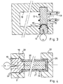
- Fig. 3 shows another possible embodiment of the locking means according to the invention.
- the bar-type element 1 comprises a bar 12 and a cylinder lock 13 which are fixed to each other in such a way that the two longitudinal axes of the bar 12 and the cylinder lock 13 coincide.
- the bar 12 is provided with a bore 14 into which a projection 15 of the cylinder lock 13 fits.
- the projection 15 and the bore 14 are provided with keyways 16, by means of which the cylinder lock 13 and the bar are connected to each other with the aid of a sprung ring 17 so that they rotate about the longitudinal axis. In this way both the bar 12 and the cylinder lock 13 can turn about the longitudinal axis relative to each other and independently of each other.
- This lock is designed as a stirrup lock 18 which could be mounted on, for example, a bicycle. It is also possible to use the bar-type element for fastening the two ends of a chain 19 to it, so that a bicycle can be fastened to, say, a post.
- Fig. 4 shows yet another possible embodiment of the locking means according to the invention.
- This figure shows in cross section a lock 14 for a bicycle which can be designed just like the stirrup lock shown in Fig. 3.
- a stirrup lock can then be mounted with a pair of bolts on the bicycle, preferably near the carrier.
- the bar of the bar-type element 1 comprises a sleeve 20 with a central bore accommodating a preferably hardened metal bar 21.
- the sleeve 20 is rotatably fastened to the cylinder lock 13 in the same way as shown in Fig. 3.
- the two legs 22 of the stirrup 18 are provided with holes 23, 24 lying in line with each other.
- One hole is provided with a bottom 25, against which the bar-type element 1 comes to rest when it is in the closed position.
- the first hole is provided with a keyway 8 into which the catch 3 of the cylinder lock 13 falls.
- a bar-type element is not limited to locks such as those shown in the above figures.
- the same bar-type element as that used in a lock of the type shown can be used in a lock of the type shown in Figs. 5 and 6.
- These locks comprise a frame 26 anchored in the ground.
- the frame 26 has U-shaped or stirrup-type elements 27 which are, for example, designed in the way described in Figs. 3 and 4. This means that it is possible with such a bar-type element of a bicycle lock of the type shown in Figs. 3 and 4, fitted on a bicycle, to fasten the bicycle to such a frame; for this the bar-type element must be removed from the bicycle lock and then placed in the stirrup-type lock of the frame 26 or bicycle rack and locked.
Landscapes
- Engineering & Computer Science (AREA)
- Mechanical Engineering (AREA)
- Lock And Its Accessories (AREA)
Applications Claiming Priority (2)
| Application Number | Priority Date | Filing Date | Title |
|---|---|---|---|
| NL8701751 | 1987-07-24 | ||
| NL8701751 | 1987-07-24 |
Publications (1)
| Publication Number | Publication Date |
|---|---|
| EP0300584A1 true EP0300584A1 (en) | 1989-01-25 |
Family
ID=19850370
Family Applications (1)
| Application Number | Title | Priority Date | Filing Date |
|---|---|---|---|
| EP88201595A Withdrawn EP0300584A1 (en) | 1987-07-24 | 1988-07-22 | Locking means, and more particularly a lock for a bicycle |
Country Status (3)
| Country | Link |
|---|---|
| US (1) | US4887444A (da) |
| EP (1) | EP0300584A1 (da) |
| DK (1) | DK408588A (da) |
Cited By (1)
| Publication number | Priority date | Publication date | Assignee | Title |
|---|---|---|---|---|
| WO1997009502A1 (en) * | 1995-09-01 | 1997-03-13 | William Rossiter | A lock |
Families Citing this family (5)
| Publication number | Priority date | Publication date | Assignee | Title |
|---|---|---|---|---|
| DE4312458C2 (de) * | 1993-04-16 | 1999-11-11 | Shieh Jin Ren | Sperrvorrichtung für eine Scheibenbremse |
| JP2682958B2 (ja) * | 1994-11-02 | 1997-11-26 | 株式会社サンポウロック | 補助錠 |
| US5613387A (en) * | 1996-02-05 | 1997-03-25 | Shieh; Jin R. | Lock that can be used interchangeably as a lock and a hand tool |
| US7159423B1 (en) * | 2004-11-18 | 2007-01-09 | Kewlmetal, Inc. | Helmet locking device |
| US11053712B2 (en) * | 2019-04-01 | 2021-07-06 | Yu-Pin Lin | Chain lock |
Citations (5)
| Publication number | Priority date | Publication date | Assignee | Title |
|---|---|---|---|---|
| FR949650A (fr) * | 1941-10-01 | 1949-09-05 | Serrure de sûreté notamment cadenas et verrou fixe | |
| US3820283A (en) * | 1972-09-14 | 1974-06-28 | J Shramovich | Locking system and lock therefor |
| US4120183A (en) * | 1976-07-22 | 1978-10-17 | Bmr Security Products Corp. | Lock assembly for high security container |
| DE2918865B1 (de) * | 1979-05-10 | 1980-10-23 | Neiman Gmbh & Co Kg | Steckschloss |
| EP0102621A2 (de) * | 1982-09-01 | 1984-03-14 | Firma Aug. Winkhaus | Steckriegelschloss, insbesondere für Zweiradfahrzeuge |
Family Cites Families (4)
| Publication number | Priority date | Publication date | Assignee | Title |
|---|---|---|---|---|
| US924331A (en) * | 1909-03-05 | 1909-06-08 | Raffaele Feola | Lock. |
| US3391555A (en) * | 1967-12-20 | 1968-07-09 | Anthony Mamo | Locking device for a trailer hitch |
| US3988910A (en) * | 1974-09-10 | 1976-11-02 | Gkn-Stenman Ab | Locking device for a spoke wheel of a bicycle, moped or similar vehicle |
| US4064716A (en) * | 1976-04-05 | 1977-12-27 | The Shwayder Company | Saw resistant lock |
-
1988
- 1988-07-21 DK DK408588A patent/DK408588A/da not_active Application Discontinuation
- 1988-07-22 EP EP88201595A patent/EP0300584A1/en not_active Withdrawn
- 1988-07-25 US US07/223,496 patent/US4887444A/en not_active Expired - Fee Related
Patent Citations (5)
| Publication number | Priority date | Publication date | Assignee | Title |
|---|---|---|---|---|
| FR949650A (fr) * | 1941-10-01 | 1949-09-05 | Serrure de sûreté notamment cadenas et verrou fixe | |
| US3820283A (en) * | 1972-09-14 | 1974-06-28 | J Shramovich | Locking system and lock therefor |
| US4120183A (en) * | 1976-07-22 | 1978-10-17 | Bmr Security Products Corp. | Lock assembly for high security container |
| DE2918865B1 (de) * | 1979-05-10 | 1980-10-23 | Neiman Gmbh & Co Kg | Steckschloss |
| EP0102621A2 (de) * | 1982-09-01 | 1984-03-14 | Firma Aug. Winkhaus | Steckriegelschloss, insbesondere für Zweiradfahrzeuge |
Cited By (1)
| Publication number | Priority date | Publication date | Assignee | Title |
|---|---|---|---|---|
| WO1997009502A1 (en) * | 1995-09-01 | 1997-03-13 | William Rossiter | A lock |
Also Published As
| Publication number | Publication date |
|---|---|
| DK408588D0 (da) | 1988-07-21 |
| DK408588A (da) | 1989-01-25 |
| US4887444A (en) | 1989-12-19 |
Similar Documents
| Publication | Publication Date | Title |
|---|---|---|
| US5148690A (en) | Two-section type pickproof lock assembly | |
| US3841118A (en) | Cable lock | |
| US5505064A (en) | Shackle lock | |
| US4621873A (en) | Quick release assembly with integral lock | |
| US4938040A (en) | Securing device for surfboards | |
| US4112716A (en) | Padlock device | |
| US5214945A (en) | Locking assembly for use on a nut or bolt head | |
| US3855824A (en) | Key retaining lock | |
| US6530248B1 (en) | Lock device | |
| US5797284A (en) | High security handcuffs | |
| EP0675995B1 (en) | Lock | |
| US6341509B1 (en) | Tie lock assemblage with replaceable lock mechanism | |
| US4987753A (en) | Padlock | |
| US4064716A (en) | Saw resistant lock | |
| HK1002322B (en) | Lock | |
| US4693098A (en) | Non-key locking cable lock | |
| US4887444A (en) | Locking means, and more particularly a lock for a bicycle | |
| US4845967A (en) | Spring-free locking cable lock | |
| US4051703A (en) | Bicycle lock | |
| US3738132A (en) | Chain lock | |
| EP0658238B1 (en) | Padlocks | |
| US5730012A (en) | Bicycle sprocket lock | |
| US5005389A (en) | Steering wheel lock | |
| EP1065334A1 (en) | Lock cylinder | |
| US5881588A (en) | Security lock |
Legal Events
| Date | Code | Title | Description |
|---|---|---|---|
| PUAI | Public reference made under article 153(3) epc to a published international application that has entered the european phase |
Free format text: ORIGINAL CODE: 0009012 |
|
| AK | Designated contracting states |
Kind code of ref document: A1 Designated state(s): AT BE CH DE ES FR GB GR IT LI LU NL SE |
|
| RIN1 | Information on inventor provided before grant (corrected) |
Inventor name: DE BROUWER, THOMAS WILLEM HENDRIK |
|
| RIN1 | Information on inventor provided before grant (corrected) |
Inventor name: DE BROUWER, THOMAS WILLEM HENDRIK |
|
| RIN1 | Information on inventor provided before grant (corrected) |
Inventor name: DE BROUWER, THOMAS WILLEM HENDRIK |
|
| 17P | Request for examination filed |
Effective date: 19890523 |
|
| 17Q | First examination report despatched |
Effective date: 19901114 |
|
| STAA | Information on the status of an ep patent application or granted ep patent |
Free format text: STATUS: THE APPLICATION IS DEEMED TO BE WITHDRAWN |
|
| 18D | Application deemed to be withdrawn |
Effective date: 19920414 |