EP0300616A1 - Appareil de mesure d epaisseur d une paroi - Google Patents
Appareil de mesure d epaisseur d une paroi Download PDFInfo
- Publication number
- EP0300616A1 EP0300616A1 EP88305578A EP88305578A EP0300616A1 EP 0300616 A1 EP0300616 A1 EP 0300616A1 EP 88305578 A EP88305578 A EP 88305578A EP 88305578 A EP88305578 A EP 88305578A EP 0300616 A1 EP0300616 A1 EP 0300616A1
- Authority
- EP
- European Patent Office
- Prior art keywords
- wall thickness
- capacitive
- elements
- probe
- detector according
- Prior art date
- Legal status (The legal status is an assumption and is not a legal conclusion. Google has not performed a legal analysis and makes no representation as to the accuracy of the status listed.)
- Granted
Links
- 238000005259 measurement Methods 0.000 title description 4
- 239000000523 sample Substances 0.000 claims abstract description 73
- 238000007689 inspection Methods 0.000 claims abstract description 39
- 239000010410 layer Substances 0.000 claims description 41
- 239000011888 foil Substances 0.000 claims description 6
- 239000011241 protective layer Substances 0.000 claims description 5
- 239000000463 material Substances 0.000 claims description 4
- 239000006260 foam Substances 0.000 claims description 3
- 239000004033 plastic Substances 0.000 claims description 3
- 229920003023 plastic Polymers 0.000 claims description 3
- 229920001084 poly(chloroprene) Polymers 0.000 claims description 2
- 229920001296 polysiloxane Polymers 0.000 claims description 2
- 239000004020 conductor Substances 0.000 claims 1
- 239000006263 elastomeric foam Substances 0.000 claims 1
- 239000011521 glass Substances 0.000 description 10
- RYGMFSIKBFXOCR-UHFFFAOYSA-N Copper Chemical compound [Cu] RYGMFSIKBFXOCR-UHFFFAOYSA-N 0.000 description 7
- 239000011889 copper foil Substances 0.000 description 7
- 239000004809 Teflon Substances 0.000 description 6
- 229920006362 Teflon® Polymers 0.000 description 6
- 239000003989 dielectric material Substances 0.000 description 4
- 239000003990 capacitor Substances 0.000 description 3
- 230000005672 electromagnetic field Effects 0.000 description 3
- 239000004593 Epoxy Substances 0.000 description 2
- 239000013536 elastomeric material Substances 0.000 description 2
- 229920002620 polyvinyl fluoride Polymers 0.000 description 2
- 239000004743 Polypropylene Substances 0.000 description 1
- 239000004820 Pressure-sensitive adhesive Substances 0.000 description 1
- 229910000639 Spring steel Inorganic materials 0.000 description 1
- 239000004699 Ultra-high molecular weight polyethylene Substances 0.000 description 1
- 230000006835 compression Effects 0.000 description 1
- 238000007906 compression Methods 0.000 description 1
- 238000013461 design Methods 0.000 description 1
- 238000010586 diagram Methods 0.000 description 1
- 230000000694 effects Effects 0.000 description 1
- 239000005357 flat glass Substances 0.000 description 1
- 229920002457 flexible plastic Polymers 0.000 description 1
- 239000012530 fluid Substances 0.000 description 1
- 238000009413 insulation Methods 0.000 description 1
- 238000000034 method Methods 0.000 description 1
- 238000012986 modification Methods 0.000 description 1
- 230000004048 modification Effects 0.000 description 1
- 230000035515 penetration Effects 0.000 description 1
- -1 polypropylene Polymers 0.000 description 1
- 229920001155 polypropylene Polymers 0.000 description 1
- 230000005855 radiation Effects 0.000 description 1
- 238000006467 substitution reaction Methods 0.000 description 1
- 238000012360 testing method Methods 0.000 description 1
- 238000013519 translation Methods 0.000 description 1
- 229920000785 ultra high molecular weight polyethylene Polymers 0.000 description 1
Images


Classifications
-
- G—PHYSICS
- G01—MEASURING; TESTING
- G01B—MEASURING LENGTH, THICKNESS OR SIMILAR LINEAR DIMENSIONS; MEASURING ANGLES; MEASURING AREAS; MEASURING IRREGULARITIES OF SURFACES OR CONTOURS
- G01B7/00—Measuring arrangements characterised by the use of electric or magnetic techniques
- G01B7/02—Measuring arrangements characterised by the use of electric or magnetic techniques for measuring length, width or thickness
- G01B7/06—Measuring arrangements characterised by the use of electric or magnetic techniques for measuring length, width or thickness for measuring thickness
- G01B7/08—Measuring arrangements characterised by the use of electric or magnetic techniques for measuring length, width or thickness for measuring thickness using capacitive means
-
- B—PERFORMING OPERATIONS; TRANSPORTING
- B07—SEPARATING SOLIDS FROM SOLIDS; SORTING
- B07C—POSTAL SORTING; SORTING INDIVIDUAL ARTICLES, OR BULK MATERIAL FIT TO BE SORTED PIECE-MEAL, e.g. BY PICKING
- B07C5/00—Sorting according to a characteristic or feature of the articles or material being sorted, e.g. by control effected by devices which detect or measure such characteristic or feature; Sorting by manually actuated devices, e.g. switches
- B07C5/04—Sorting according to size
- B07C5/12—Sorting according to size characterised by the application to particular articles, not otherwise provided for
- B07C5/122—Sorting according to size characterised by the application to particular articles, not otherwise provided for for bottles, ampoules, jars and other glassware
- B07C5/128—Sorting according to size characterised by the application to particular articles, not otherwise provided for for bottles, ampoules, jars and other glassware by means of electric, for example electronic measurement
-
- B—PERFORMING OPERATIONS; TRANSPORTING
- B07—SEPARATING SOLIDS FROM SOLIDS; SORTING
- B07C—POSTAL SORTING; SORTING INDIVIDUAL ARTICLES, OR BULK MATERIAL FIT TO BE SORTED PIECE-MEAL, e.g. BY PICKING
- B07C5/00—Sorting according to a characteristic or feature of the articles or material being sorted, e.g. by control effected by devices which detect or measure such characteristic or feature; Sorting by manually actuated devices, e.g. switches
- B07C5/34—Sorting according to other particular properties
- B07C5/3404—Sorting according to other particular properties according to properties of containers or receptacles, e.g. rigidity, leaks, fill-level
- B07C5/3408—Sorting according to other particular properties according to properties of containers or receptacles, e.g. rigidity, leaks, fill-level for bottles, jars or other glassware
Definitions
- the invention relates generally to inspection apparatus and deals more particularly with a wall thickness detector for glassware, flat glass and other products.
- Wall thickness is an important factor throughout the glass industry because a thin wall region increases the likelihood of breakage.
- To measure the wall thickness of glass bottles it was previously known to rotate the glass bottles at an inspection site to expose a circumferential band to a wall thickness probe.
- Various capacitive probes have been utilized to indirectly measure the wall thickness.
- U.S. Patent No. 3,684,089 to McMeekan discloses a capacitive probe comprising a plurality of electrodes made of spring steel which engage sidewalls of a glass container as the container is rotated. The electrodes are part of a bridge and the resultant capacitance exhibited by the electrodes in contact with the glass sidewall indicates the wall thickness.
- U.S. Patent No. 2,285,152 to Firestone discloses a capacitive probe comprising two electrodes which are placed in contact with one surface of a container and the capacitance between them measured.
- U.S. Patent No. 3,629,699 to Voss discloses apparatus for dielectric testing of containers in which an expandable plate is inserted through the mouth of a bottle and positioned adjacent to the bottom. Another plate is raised to the bottom sur face of the bottle and the capacitance between the two plates is measured.
- U.S. Patent No. 3,393,799 to Schmersal discloses apparatus for measuring the thickness of dielectric members and includes an antenna which is biased from the outer sidewalls of the container by a contact wheel.
- U.S. Patent No. 2,601,649 to Wadman discloses apparatus for measuring the thickness of dielectric material and includes a single spherical electrode which contacts the container sidewall.
- U.S. Patent No. 2,616,068 to McDonald discloses apparatus for measuring the thickness of dielectric material and includes a single electrode which is resilient pressed into a rotatable engagement with a container by means of compression springs.
- U.S. Patent No. 2,573,824 to Baker discloses apparatus for measuring the thickness of dielectric material and includes a main capacitor plate 71 which is accurately shaped and supported adjacent to the periphery of a container. Capacitor pick-up plates are also provided exterior to its base slightly from the container.
- U.S. Patent No. 3,708,064 to Schepler discloses apparatus and method for measuring the wall thickness of dielectric materials and includes an RF antenna supported adjacent to but apparently not in contact with the exterior of the container and a coaxial receiver probe which measures the strength of the resultant electromagnetic field.
- U.S. Patent No. 3,710,938 to Scherf discloses an apparatus for detecting wall thickness in which an RF field is established in the vicinity of a glass container and the magnitude of the field as effected by the container is measured to indicate wall thickness.
- a general object of the invention is to provide a wall thickness detector which is accurate at a high speed of operation.
- Another general object of the present invention is to provide a wall thickness detector which measures the thickness at a defined area.
- a more specific object the present invention is to provide wall thickness detectors of the foregoing types which are suitable to measure the thickness of the sidewalls of glass bottles and require ordinary means to rotate the glass bottle during the inspection.
- the invention resides in an inspection apparatus for detecting wall thickness of a dielectric body, the apparatus having a conveyor for transporting a plurality of the dielectric bodies serially to an inspection site and a means for rotating the dielectric bodies at the inspection site.
- the inspection apparatus includes a capacitive probe having a plurality of flexible capacitive elements and an elastic body supporting the flexible capacitive elements. The capacitive probe is supported such that the elastic body receives each of the dielectric bodies at the inspection site and biases the flexible capacitive elements toward the dielectric body to contour the dielectric body at the inspection site.
- An electronic means determines wall thickness based on the capacitance provided by the capacitive probe.
- the elastic body comprises foamed plastic.
- a first metallic shield is supported between the elastic body and the capacitive elements and a second metallic shield is supported on the other side of the capacitive elements in close proximity thereto and has a window means for exposing the capacitive elements to the dielectric body.
- One of the capacitive elements and the two shields are driven with a common voltage waveform.
- Figure 1 illustrates a container inspection station generally designated 10 which includes a linear conveyor 12 of conventional design and a feed screw 14 which spaces and sequentially moves containers such as a glass bottle 15 to an inspection site.
- the container 15 engages a horizontally moving endless belt 24 which rotates the bottle 15, and a pair of flanged, finish rollers 38 and 40 are lowered against the bottle mouth to hold the bottle down during the rotation.
- the bottle engages a capacitive probe 49 of a thin wall detector 50.
- the thin wall detector 50 also includes a support 51 and a bracket plate or clamp 54 which support the capacitive probe 49.
- the detector 50 While the capacitive probe 49 is generally maintained in a stationary position as shown, the detector 50 includes an overdrive spring 56 which allows the capacitive probe 49 to withdraw from contact with an oversized or overturned bottle which inadvertently attempts to pass through the inspection station.
- an overdrive spring 56 which allows the capacitive probe 49 to withdraw from contact with an oversized or overturned bottle which inadvertently attempts to pass through the inspection station.
- the bottle 15 is rotated by the belt 24 so that the capacitive probe 49 engages and thereby senses a circumferential band extending completely around the bottle 15.
- the capacitive probe 49 may be adjusted to correspond to a likely thin wall location or, if desired, a plurality of the wall thickness detectors may be utilized to inspect different vertical portions of the bottle.
- a plurality of the wall thickness detectors may be utilized to inspect different vertical portions of the bottle.
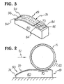
- Figure 2 is a top view of the capacitive probe 49 in engagement with and receipt of the bottle 15.
- a leading or front edge 60 of the probe 49 is ta pered inwardly to allow the bottle 15 to move on the conveyor 12 along it without catching the front edge.
- the bottle 15 continues to move along the probe 49 linearly in the direction of an arrow 61 until it reaches the inspection site and then is rotated as indicated by an arrow 63.
- the wall thickness detector 50 including the probe 49 is transported linearly by a carriage 20 ( Figure 1) in timed relation with the linear motion of the bottle 15 on the conveyor 12. Consequently, the bottle 15 maintains engagement with a capacitive measurement portion 70 of the probe 49 for at least one complete rotation of the bottle 15.
- the capacitive probe 49 includes an outer, low-wear layer 72 which protects the probe 49 which layer may, by way of example, comprise an ultra-high molecular weight polyethylene with a pressure sensitive adhesive on its under surface which bonds it to a flexible capacitive circuit board 74 underneath.
- the protective layer 72 may comprise a polyvinyl fluoride material. In addition to protecting the remainder of the capacitive probe 49, the protective layer 72 provides a low resistance to minimize drag on the bottle 15 during its linear translation on the conveyor and rotation relative to the probe 49.
- the capacitive probe 49 also includes a resilient support body 80 which, by way of example, may comprise an elastomeric material or any other form of elastic device such as a flexible bladder containing gas or fluid under suitable pressure.
- the support body 80 is made of silicone or neoprene foam.
- Such an elastomeric material as the foam provides a high stiffness to weight ratio, low inertia, high heat resistance, omnidirectional resiliency and a consistent electrical characteristic over a wide temperature range.
- the support body 80 provides a multidirectional pressure profile on the capacitive circuit board 74 causing the capacitive circuit board to contour the cylindrical sidewall of the bottle which will insure uniform, close spacing between the capacitive elements and the bottle surface throughout the operating range of the probe.
- FIGs 3-4 further illustrate the capacitive probe 49 except that the protective layer 72 is not shown in Figure 3 to give a clearer view of the flexible capacitive circuit board 74.
- the circuit board 74 comprises a top layer 76 illustrated in Figure 4(a), a middle layer 78 illustrated in Figure 4(b) and a bottom layer 380 illustrated in Figure 4(c).
- the top layer 76 is a capacitive shield or guard and, by way of example, is formed from copper foil.
- the protective layer 72 is bonded to the upper surface of the top layer 76 and covers a window 81 within the top layer 76.
- the foil is 0.001 inches (0.025 mm) thick.
- the shield is designed to eliminate variations in capacitance which are not associated with bottle thickness but which will affect the measurement absent the capacitive shield.
- the shield layer 76 includes the window 81 to expose capacitive elements 84 and 86 discussed below.
- Figure 4(a) also illustrates a Teflon layer 83 bonded to the underside of the layer 76 to insulate the capacitive shield layer 76 from the underlying layer 78.
- the Teflon layer is approximately 0.002 inches (0.05 mm) thick and utilize an epoxy to bond the teflon to the shield layer 76.
- the middle layer 78 includes the capacitive elements 84, 84 and 86 which elements may, for example, comprise copper foil strips bonded to a thin flexible plastic base 91.
- the plastic base 91 comprises polypropylene or Tedlar 0.002 inches (0.05 mm) thick.
- the capacitive probes 84, 84 and 86 taper to thin strips of the copper foil and continue over much of the length of the capacitive probe 49 until they terminate in contact pads 94, 94 and 96 respectively which also, by way of example, comprise copper foil.
- the contact pads 94, 94 and 96 protrude from the end 60 of the capacitive probe 49 to facilitate electrical connection to wires which connect to an electronic processor 100 described below.
- a rigid printed circuit board may be interposed between the capacitive elements and the wires.
- the copper foil of the middle layer 78 does not make an electrical contact with the shield layer 76, and because of the window 81, the capacitive elements 84, 84 and 86 are not shielded. As described in more detail below, a non-zero voltage waveform is applied to the capacitive element 86 which generates a field and the capacitive elements 84, 84 are shorted to one another and grounded to receive the field.
- the field emanating from the capacitive element 86 is confined to a region approximately bounded by planes through and normal to the capacitive elements 84, 84 which field is also preferably confined to the side of the capacitive probe 49 adjacent to the bottle 15 because of the layer 380 below. Consequently, the field emanates over a defined portion of the bottle sidewall.
- the bottom layer 380 also, by way of example, comprises copper foil approximately 0.001 inches (0.025 mm) thick and serves to shield the capacitive elements 84, 84 and 86 below so that they are not affected by matters occurring on the side of the capacitive probe 49 opposite the bottle 15.
- Windows 101 are provided in the shield layer 380 to limit the radiation from the shield layer 380 to the capacitive elements 84, 84 because, as described below, the copper foils of the two shield layers are driven with the same voltage waveform as the capacitive element 84.
- a Teflon layer 104 is bonded by epoxy to the upper surface of the bottom layer 380 to prevent an electrical connection between the foil of the bottom layer 380 and the foil strips of the middle layer 78.
- the unshielded portion 70 of the capacitive probe 49 is included within an arc of contact of the bottle to obtain a reliable measurement. This is accomplished by setting the bottle penetration into the capacitive probe 49 by an amount which produces an arc of contact approximately 20% greater than a length 106 of the window 81.
- the electromagnetic field established between the capacitive elements 84, 84 and 86 corresponds to the thickness and dielectric property of the bottle 15 sidewall so that variations in such thickness affect the capacitance established by the capacitive elements 84, 84 and 86.
- Such capacitances are utilized in the electronic processor 100 to determine the wall thickness as a function of time during the rotation of the bottle.
- the electronic processor 100 includes a reference oscillator 110, which supplies a voltage waveform having a constant frequency to phase detector 112. Another input of the phase detector 112 is supplied by an output of a voltage controlled oscillator 116.
- the capacitive elements 84, 84 and 86 are connected to control ports 121, 123 of the voltage controlled oscillator 116 by wires 117, 117 and 119 so that the capacitance developed between the capacitive elements 84, 84 and 86 determines the output frequency of the voltage controlled oscillator 116.
- the voltage controlled oscillator 116 applies its voltage waveform to the capacitive element 86, and the port 121 provides a ground.
- the output of the phase detector 112 is a function of the difference in phase between the reference oscillator 110 and the voltage controlled oscillator 116 and is supplied to a low pass filter 114.
- the output 120 may be supplied to one input of a comparator 122, the other input of the comparator supplied by a reference voltage, and the output of the comparator supplied to a rejector 124 so that if the wall thickness at any portion on the bottle under inspection is less than a predetermined level, the output voltage will be greater than the reference voltage and the rejector 124 will be activated to reject the bottle.
- Figure 5 also illustrates that the voltage controlled oscillator 116 supplies its voltage waveform to the foils of the shield layers 76 and 380 via a buffer 153 and wires 155 and 157 which are soldered to the foils of the shield layers 76 and 80, respectively.
- FIGs 6 and 7 illustrate an inspection apparatus generally designated 300 including a wall thickness detector 302 and a capacitive probe 304.
- the inspection apparatus 300 is similar to the inspection apparatus 10 except as follows, and like reference numerals indicate like elements.
- the capacitive probe 304 is supported for horizontal, reciprocal movement by a plunger 18 mounted on the horizontally movable carriage 20.
- the plunger 18 and the capacitive probe 304 are retracted so that the capacitive probe 304 does not engage the bottle 15.
- the plunger 18 is extended to urge the capacitive probe 304 against the sidewall of the bottle 15.
- This is the state of the wall thickness detector 302 illustrated in Figure 7. In this state, the bottle 15 engages the region 70 of the capacitive element 304. Consequently, the bottle 15 does not drag against the capacitive probe 304 enroute to the inspection site.
- the only other difference between the capacitive probe 304 and the capacitive probe 49 is that an end 308 of the capacitive probe 304 is not tapered; tapering is not necessary because of the fact that the bottle 15 does not rub against the capacitive probe 304 enroute to the inspection site. Consequently, in the capacitor probe 304 the flexible capacitive circuit board 74 is unchanged, and a support body 312 of the capacitive probe 304 is block-shaped without the tapered end present in the support body 80 of the capacitive probe 304.
- the bottle 15 is rotated and the plunger 18 and the capacitive probe 304 are moved linearly by the carriage 20 in synchronism with the conveyor 12 as in the inspection apparatus 10. After one or more complete rotations of the bottle 15, the plunger 18 is withdrawn to a position out of engagement with the bottle 15 and the bottle is free to continue along the conveyor 12 out of the inspection site.
- the back of shield layer 400 illustrated in Figure 8 having a Teflon insulation layer 402 in place of the shield layer 380 may be desirable to shield the back of shield layer 400 illustrated in Figure 8 having a Teflon insulation layer 402 in place of the shield layer 380 to improve the flexibility of the circuit board.
- the backs of the other ground electrodes are unshielded and the front of all of the electrodes will still be framed by the shield layer 76 with the window 81 to expose the front of all of the electrodes to the bottle. Therefore, the invention has been disclosed by way of illustration and not limitation.
Landscapes
- Physics & Mathematics (AREA)
- General Physics & Mathematics (AREA)
- Measurement Of Length, Angles, Or The Like Using Electric Or Magnetic Means (AREA)
Applications Claiming Priority (2)
| Application Number | Priority Date | Filing Date | Title |
|---|---|---|---|
| US69457 | 1987-07-02 | ||
| US07/069,457 US4820972A (en) | 1987-07-02 | 1987-07-02 | Wall thickness detector |
Publications (2)
| Publication Number | Publication Date |
|---|---|
| EP0300616A1 true EP0300616A1 (fr) | 1989-01-25 |
| EP0300616B1 EP0300616B1 (fr) | 1992-09-30 |
Family
ID=22089088
Family Applications (1)
| Application Number | Title | Priority Date | Filing Date |
|---|---|---|---|
| EP88305578A Expired EP0300616B1 (fr) | 1987-07-02 | 1988-06-17 | Appareil de mesure d epaisseur d une paroi |
Country Status (6)
| Country | Link |
|---|---|
| US (1) | US4820972A (fr) |
| EP (1) | EP0300616B1 (fr) |
| JP (1) | JPS6425001A (fr) |
| AU (1) | AU599297B2 (fr) |
| DE (1) | DE3874999T2 (fr) |
| MX (1) | MX162867B (fr) |
Cited By (8)
| Publication number | Priority date | Publication date | Assignee | Title |
|---|---|---|---|---|
| EP0363116A3 (en) * | 1988-10-05 | 1990-09-05 | Emhart Industries, Inc. | Glass container wall thickness inspection apparatus |
| EP0363115A3 (en) * | 1988-10-05 | 1990-09-05 | Emhart Industries, Inc. | Glass container wall thickness inspection apparatus |
| EP0491545A1 (fr) * | 1990-12-19 | 1992-06-24 | Emhart Glass Machinery Investments Inc. | Machine pour vérifier l'épaisseur du parois de bouteilles en verre |
| EP0544022A1 (fr) * | 1990-10-09 | 1993-06-02 | Agr International, Inc. | Appareil et procédé d'inspection de l'épaisseur des parois d'un récipient en verre |
| FR2724454A1 (fr) * | 1994-09-12 | 1996-03-15 | Vmc | Dispositif de controle de l'epaisseur d'articles manufactures, notamment au niveau des zones de discontinuite |
| EP1715335A1 (fr) * | 2005-04-22 | 2006-10-25 | Mectron Engineering Company | Systeme de controle de piece |
| EP2570767A1 (fr) * | 2011-09-19 | 2013-03-20 | United Technologies Corporation | Dispositif pour mesurer le radius d'un objet |
| EP2889574A4 (fr) * | 2012-09-28 | 2016-06-01 | Nihon Yamamura Glass Co Ltd | Dispositif d'inspection d'épaisseur |
Families Citing this family (16)
| Publication number | Priority date | Publication date | Assignee | Title |
|---|---|---|---|---|
| US4965523A (en) * | 1988-10-05 | 1990-10-23 | Emhart Industries, Inc. | Glass container inspection machine with rejection parameter selector |
| US5030918A (en) * | 1989-11-17 | 1991-07-09 | Modern Controls, Inc. | Portable gauge for measuring thickness variations of thin plastic film |
| US5121068A (en) * | 1989-12-26 | 1992-06-09 | Emhart Industries, Inc. | Sensor for sensing the wall thickness of an object |
| US5144269A (en) * | 1990-03-20 | 1992-09-01 | Sanyo Electric Co., Ltd. | Dielectric filter having external connection formed on dielectric substrate |
| US5214398A (en) * | 1990-10-31 | 1993-05-25 | Ube Industries, Ltd. | Dielectric filter coupling structure having a compact terminal arrangement |
| US5225783A (en) * | 1991-02-18 | 1993-07-06 | Mitsubishi Denki Kabushiki Kaisha | Dielectric constant detection apparatus for fuel |
| US5532605A (en) * | 1994-10-27 | 1996-07-02 | Agr International, Inc. | Container inspection apparatus having diameter measuring means and associated method |
| US5558233A (en) * | 1994-10-27 | 1996-09-24 | Agr International, Inc. | Container inspection apparatus for determining the wall thickness of non-round containers and associated method |
| US5739696A (en) * | 1996-08-08 | 1998-04-14 | Herrmann; Jakob | Probe and apparatus for testing electronic components |
| US6536294B1 (en) * | 1997-05-14 | 2003-03-25 | Emhart Glass S.A. | Inspection machine |
| FR2877093B1 (fr) * | 2004-10-21 | 2007-01-26 | Sidel Sas | Procede de mesure capacitive d'une caracteristique d'un recipient thermoplastique dans un moule, moule ainsi equipe, procede de fabrication du moule, et installation de moulage equipe du moule |
| US7730789B2 (en) * | 2006-11-01 | 2010-06-08 | Boeing Management Company | Device and method for measuring a gap between members of a structure for manufacture of a shim |
| US20100136696A1 (en) * | 2006-12-29 | 2010-06-03 | Cargill Incorporated | Apparatus and method for the enhancement of contaminant detection |
| US7971666B2 (en) | 2007-06-20 | 2011-07-05 | Ford Global Technologies, Llc | System and method of extending regenerative braking in a hybrid electric vehicle |
| US8548771B2 (en) | 2008-05-13 | 2013-10-01 | Emhart Glass S.A. | Out-of-round container detection system and method |
| JP6636464B2 (ja) * | 2015-01-21 | 2020-01-29 | 日本山村硝子株式会社 | 容器の肉厚検査装置 |
Citations (3)
| Publication number | Priority date | Publication date | Assignee | Title |
|---|---|---|---|---|
| DE1040263B (de) * | 1957-02-06 | 1958-10-02 | Ragnar Veimo | Verfahren und Apparat zur Messung der Dicke von duennen isolierenden Schichten |
| US3684089A (en) * | 1970-09-21 | 1972-08-15 | Brockway Glass Co Inc | Container wall thickness detection |
| FR2365785A1 (fr) * | 1976-09-24 | 1978-04-21 | Popenoe Charles | Transducteur de microdeplacement |
Family Cites Families (5)
| Publication number | Priority date | Publication date | Assignee | Title |
|---|---|---|---|---|
| US2573824A (en) * | 1946-10-17 | 1951-11-06 | Emhart Mfg Co | Machine for high-frequency determinations of wall thickness of bottles and the like |
| US2616068A (en) * | 1948-06-02 | 1952-10-28 | Emhart Mfg Co | Apparatus for gauging thickness |
| US3393799A (en) * | 1966-12-21 | 1968-07-23 | Owens Illinois Inc | Apparatus for measuring the thickness of dielectric members |
| US4103226A (en) * | 1976-09-15 | 1978-07-25 | Westinghouse Electric Corp. | Apparatus for gauging the texture of a conducting surface |
| US4482860A (en) * | 1981-12-11 | 1984-11-13 | Extrude Hone Corporation | Capacitance measurement probe |
-
1987
- 1987-07-02 US US07/069,457 patent/US4820972A/en not_active Expired - Fee Related
-
1988
- 1988-06-17 EP EP88305578A patent/EP0300616B1/fr not_active Expired
- 1988-06-17 DE DE8888305578T patent/DE3874999T2/de not_active Expired - Fee Related
- 1988-06-21 JP JP63153355A patent/JPS6425001A/ja active Pending
- 1988-07-01 MX MX12134A patent/MX162867B/es unknown
- 1988-07-01 AU AU18679/88A patent/AU599297B2/en not_active Ceased
Patent Citations (3)
| Publication number | Priority date | Publication date | Assignee | Title |
|---|---|---|---|---|
| DE1040263B (de) * | 1957-02-06 | 1958-10-02 | Ragnar Veimo | Verfahren und Apparat zur Messung der Dicke von duennen isolierenden Schichten |
| US3684089A (en) * | 1970-09-21 | 1972-08-15 | Brockway Glass Co Inc | Container wall thickness detection |
| FR2365785A1 (fr) * | 1976-09-24 | 1978-04-21 | Popenoe Charles | Transducteur de microdeplacement |
Cited By (8)
| Publication number | Priority date | Publication date | Assignee | Title |
|---|---|---|---|---|
| EP0363116A3 (en) * | 1988-10-05 | 1990-09-05 | Emhart Industries, Inc. | Glass container wall thickness inspection apparatus |
| EP0363115A3 (en) * | 1988-10-05 | 1990-09-05 | Emhart Industries, Inc. | Glass container wall thickness inspection apparatus |
| EP0544022A1 (fr) * | 1990-10-09 | 1993-06-02 | Agr International, Inc. | Appareil et procédé d'inspection de l'épaisseur des parois d'un récipient en verre |
| EP0491545A1 (fr) * | 1990-12-19 | 1992-06-24 | Emhart Glass Machinery Investments Inc. | Machine pour vérifier l'épaisseur du parois de bouteilles en verre |
| FR2724454A1 (fr) * | 1994-09-12 | 1996-03-15 | Vmc | Dispositif de controle de l'epaisseur d'articles manufactures, notamment au niveau des zones de discontinuite |
| EP1715335A1 (fr) * | 2005-04-22 | 2006-10-25 | Mectron Engineering Company | Systeme de controle de piece |
| EP2570767A1 (fr) * | 2011-09-19 | 2013-03-20 | United Technologies Corporation | Dispositif pour mesurer le radius d'un objet |
| EP2889574A4 (fr) * | 2012-09-28 | 2016-06-01 | Nihon Yamamura Glass Co Ltd | Dispositif d'inspection d'épaisseur |
Also Published As
| Publication number | Publication date |
|---|---|
| AU1867988A (en) | 1989-01-05 |
| MX162867B (es) | 1991-07-02 |
| EP0300616B1 (fr) | 1992-09-30 |
| US4820972A (en) | 1989-04-11 |
| AU599297B2 (en) | 1990-07-12 |
| DE3874999D1 (de) | 1992-11-05 |
| JPS6425001A (en) | 1989-01-27 |
| DE3874999T2 (de) | 1993-02-25 |
Similar Documents
| Publication | Publication Date | Title |
|---|---|---|
| EP0300616A1 (fr) | Appareil de mesure d epaisseur d une paroi | |
| JP3149184B2 (ja) | パッケージのテスト | |
| US5097216A (en) | Apparatus for inspecting the wall thickness of a container and corresponding method | |
| US6420866B1 (en) | Apparatus and method for detecting metallized containers in closed packages | |
| JPWO2019216274A1 (ja) | 静電容量測定回路及び静電容量変位計 | |
| US3684089A (en) | Container wall thickness detection | |
| EP0709649B1 (fr) | Inspection des récipients avec dispositif de mesure de diamètre | |
| EP1698870B1 (fr) | Cellule de charge capacitive avec des coussins en mousse imprégné de silicone. | |
| KR100351694B1 (ko) | 전하측정장치 | |
| US3833852A (en) | Inspection head mounting apparatus | |
| CN107219449A (zh) | 检查夹具、检查装置及检查方法 | |
| US3708064A (en) | Method and apparatus for inspecting dielectric members | |
| US4423628A (en) | Method and apparatus for monitoring the length of a liquid column | |
| US3879993A (en) | Method and apparatus for inspecting glass containers | |
| US4922182A (en) | Auto reactance compensated non-contacting resistivity measuring device | |
| JPS6311654Y2 (fr) | ||
| JP2501710B2 (ja) | 球状物の階級判別装置 | |
| US4282483A (en) | Probe for determining p or n-type conductivity of semiconductor material | |
| CN108303600A (zh) | 一种测定被测物电磁性能的补偿系统和补偿方法 | |
| JPS59125035A (ja) | 不良検査装置 | |
| JP2501745B2 (ja) | 球状物の階級判別装置 | |
| CN216979287U (zh) | 一种箱烟封箱成像检测装置 | |
| CN221528816U (zh) | 一种pcba检测用ict设备 | |
| JP2001228136A (ja) | 缶体の検査装置 | |
| JPS59124246A (ja) | 容器の不良検査方法及び検査装置 |
Legal Events
| Date | Code | Title | Description |
|---|---|---|---|
| PUAI | Public reference made under article 153(3) epc to a published international application that has entered the european phase |
Free format text: ORIGINAL CODE: 0009012 |
|
| AK | Designated contracting states |
Kind code of ref document: A1 Designated state(s): DE FR GB IT |
|
| 17P | Request for examination filed |
Effective date: 19890717 |
|
| RAP1 | Party data changed (applicant data changed or rights of an application transferred) |
Owner name: EMHART INDUSTRIES, INC. |
|
| 17Q | First examination report despatched |
Effective date: 19910424 |
|
| RAP1 | Party data changed (applicant data changed or rights of an application transferred) |
Owner name: EMHART GLASS MACHINERY INC., |
|
| RAP1 | Party data changed (applicant data changed or rights of an application transferred) |
Owner name: EMHART GLASS MACHINERY INVESTMENTS INC. |
|
| GRAA | (expected) grant |
Free format text: ORIGINAL CODE: 0009210 |
|
| AK | Designated contracting states |
Kind code of ref document: B1 Designated state(s): DE FR GB IT |
|
| REF | Corresponds to: |
Ref document number: 3874999 Country of ref document: DE Date of ref document: 19921105 |
|
| ET | Fr: translation filed | ||
| ITF | It: translation for a ep patent filed | ||
| PG25 | Lapsed in a contracting state [announced via postgrant information from national office to epo] |
Ref country code: GB Effective date: 19930617 |
|
| PLBE | No opposition filed within time limit |
Free format text: ORIGINAL CODE: 0009261 |
|
| STAA | Information on the status of an ep patent application or granted ep patent |
Free format text: STATUS: NO OPPOSITION FILED WITHIN TIME LIMIT |
|
| 26N | No opposition filed | ||
| GBPC | Gb: european patent ceased through non-payment of renewal fee |
Effective date: 19930617 |
|
| PG25 | Lapsed in a contracting state [announced via postgrant information from national office to epo] |
Ref country code: FR Effective date: 19940228 |
|
| PG25 | Lapsed in a contracting state [announced via postgrant information from national office to epo] |
Ref country code: DE Effective date: 19940301 |
|
| REG | Reference to a national code |
Ref country code: FR Ref legal event code: ST |
|
| PG25 | Lapsed in a contracting state [announced via postgrant information from national office to epo] |
Ref country code: IT Free format text: LAPSE BECAUSE OF NON-PAYMENT OF DUE FEES Effective date: 20050617 |