EP0300663A2 - Optische Reichweitenmessung durch Messen einer Phasenverschiebung - Google Patents
Optische Reichweitenmessung durch Messen einer Phasenverschiebung Download PDFInfo
- Publication number
- EP0300663A2 EP0300663A2 EP88306327A EP88306327A EP0300663A2 EP 0300663 A2 EP0300663 A2 EP 0300663A2 EP 88306327 A EP88306327 A EP 88306327A EP 88306327 A EP88306327 A EP 88306327A EP 0300663 A2 EP0300663 A2 EP 0300663A2
- Authority
- EP
- European Patent Office
- Prior art keywords
- optical energy
- optical
- gain control
- returned
- level
- Prior art date
- Legal status (The legal status is an assumption and is not a legal conclusion. Google has not performed a legal analysis and makes no representation as to the accuracy of the status listed.)
- Granted
Links
Images


Classifications
-
- H—ELECTRICITY
- H03—ELECTRONIC CIRCUITRY
- H03G—CONTROL OF AMPLIFICATION
- H03G3/00—Gain control in amplifiers or frequency changers
- H03G3/20—Automatic control
- H03G3/30—Automatic control in amplifiers having semiconductor devices
- H03G3/3084—Automatic control in amplifiers having semiconductor devices in receivers or transmitters for electromagnetic waves other than radiowaves, e.g. lightwaves
-
- G—PHYSICS
- G01—MEASURING; TESTING
- G01S—RADIO DIRECTION-FINDING; RADIO NAVIGATION; DETERMINING DISTANCE OR VELOCITY BY USE OF RADIO WAVES; LOCATING OR PRESENCE-DETECTING BY USE OF THE REFLECTION OR RERADIATION OF RADIO WAVES; ANALOGOUS ARRANGEMENTS USING OTHER WAVES
- G01S17/00—Systems using the reflection or reradiation of electromagnetic waves other than radio waves, e.g. lidar systems
- G01S17/02—Systems using the reflection of electromagnetic waves other than radio waves
- G01S17/06—Systems determining position data of a target
- G01S17/42—Simultaneous measurement of distance and other co-ordinates
-
- G—PHYSICS
- G01—MEASURING; TESTING
- G01S—RADIO DIRECTION-FINDING; RADIO NAVIGATION; DETERMINING DISTANCE OR VELOCITY BY USE OF RADIO WAVES; LOCATING OR PRESENCE-DETECTING BY USE OF THE REFLECTION OR RERADIATION OF RADIO WAVES; ANALOGOUS ARRANGEMENTS USING OTHER WAVES
- G01S7/00—Details of systems according to groups G01S13/00, G01S15/00, G01S17/00
- G01S7/48—Details of systems according to groups G01S13/00, G01S15/00, G01S17/00 of systems according to group G01S17/00
- G01S7/481—Constructional features, e.g. arrangements of optical elements
- G01S7/4811—Constructional features, e.g. arrangements of optical elements common to transmitter and receiver
- G01S7/4812—Constructional features, e.g. arrangements of optical elements common to transmitter and receiver transmitted and received beams following a coaxial path
-
- G—PHYSICS
- G01—MEASURING; TESTING
- G01S—RADIO DIRECTION-FINDING; RADIO NAVIGATION; DETERMINING DISTANCE OR VELOCITY BY USE OF RADIO WAVES; LOCATING OR PRESENCE-DETECTING BY USE OF THE REFLECTION OR RERADIATION OF RADIO WAVES; ANALOGOUS ARRANGEMENTS USING OTHER WAVES
- G01S7/00—Details of systems according to groups G01S13/00, G01S15/00, G01S17/00
- G01S7/48—Details of systems according to groups G01S13/00, G01S15/00, G01S17/00 of systems according to group G01S17/00
- G01S7/481—Constructional features, e.g. arrangements of optical elements
- G01S7/4817—Constructional features, e.g. arrangements of optical elements relating to scanning
-
- G—PHYSICS
- G01—MEASURING; TESTING
- G01S—RADIO DIRECTION-FINDING; RADIO NAVIGATION; DETERMINING DISTANCE OR VELOCITY BY USE OF RADIO WAVES; LOCATING OR PRESENCE-DETECTING BY USE OF THE REFLECTION OR RERADIATION OF RADIO WAVES; ANALOGOUS ARRANGEMENTS USING OTHER WAVES
- G01S7/00—Details of systems according to groups G01S13/00, G01S15/00, G01S17/00
- G01S7/48—Details of systems according to groups G01S13/00, G01S15/00, G01S17/00 of systems according to group G01S17/00
- G01S7/491—Details of non-pulse systems
- G01S7/4912—Receivers
- G01S7/4918—Controlling received signal intensity, gain or exposure of sensor
-
- G—PHYSICS
- G01—MEASURING; TESTING
- G01S—RADIO DIRECTION-FINDING; RADIO NAVIGATION; DETERMINING DISTANCE OR VELOCITY BY USE OF RADIO WAVES; LOCATING OR PRESENCE-DETECTING BY USE OF THE REFLECTION OR RERADIATION OF RADIO WAVES; ANALOGOUS ARRANGEMENTS USING OTHER WAVES
- G01S17/00—Systems using the reflection or reradiation of electromagnetic waves other than radio waves, e.g. lidar systems
- G01S17/02—Systems using the reflection of electromagnetic waves other than radio waves
- G01S17/06—Systems determining position data of a target
- G01S17/08—Systems determining position data of a target for measuring distance only
- G01S17/32—Systems determining position data of a target for measuring distance only using transmission of continuous waves, whether amplitude-, frequency-, or phase-modulated, or unmodulated
- G01S17/36—Systems determining position data of a target for measuring distance only using transmission of continuous waves, whether amplitude-, frequency-, or phase-modulated, or unmodulated with phase comparison between the received signal and the contemporaneously transmitted signal
Definitions
- This invention relates to simple, low cost optical ranging by phase shift measurement, and particularly such optical ranging in which the return signal experiences a very large and rapid variation in amplitude as is typical in the use of an optical ranger as an aid for robot cart navigation in a factory environment.
- the optical ranging needed to control such a robot cart must be of very low cost and at the same time must work with scattering from surfaces of varying reflectivity and over a wide range of distances.
- the signal levels of the returning optical radiation can typically vary by more than a thousand to one, depending on the conditions.
- the rapidly increasing world-wide use of existing designs of mobile robot carts or "autonomously guided vehicles" in factories have mainly employed buried cables in the floor for vehicle guidance.
- the buried cable approach is expensive and insufficiently flexible for many of the evolving uses of mobile carts, especially for material transport.
- optical radar for ranging, typically with an infrared beam
- the primary problem to be faced is that of handling the rapidly fluctuating and large dynamic range of optical intensity expected in the received signal.
- the difficulty is not primarily the wide range of intensity per se but the fact that it needs to be handled without introducing any change in phase great enough to perturb the range measurement itself.
- a passive optical part of the level control system provides a factor of about 20 in partially compensating for the dynamic range variation of the return signals arising from distance variations, while an active electronic AGC part provides the remaining factor of about 50 dynamic range control.
- the optical aspects of the signal level control system simultaneously prevent the leakage of transmitted light directly into the receiver by virtue of the coaxial arrangement of the transmitting and receiving elements in which the shielded transmitting element is mounted in front of the receiving element.
- This large receiving aperture has resulted in the ability to determine ranges to within ⁇ 2.5 inches at 20 feet, and ⁇ 0.5 inches at 5 feet, with an overall system bandwidth of ⁇ 1 KHz, while using only 1 milliwatt of radiated optical power.
- the coaxial optics of the ranging system are such that the receiving elements intentionally block increasingly large portions of the signal as the target to which the distance is being measured becomes closer to the optical ranger.
- the electronic part of the AGC system depends heavily upon having a voltage (low internal impedance) drive for one element of the AGC amplifier when the transistor element therein would be operating in a low current portion of its operating range and therefore would tend to be slow if its driving element were in a current driving (high impedance) condition.
- the feature of the invention providing the voltage signal drive overcomes this.
- the AGC action is rapid and introduces negligible phase shift related to signal amplitude.
- FIG. 1 The essential components of FIG. 1 are shown in the simplest possible form; but it should be understood that they are all mounted on a mobile robot cart of the type used in factory environments for material transfer and inventory control. While the transmitted incoherent light beam of the ranging system from LED 12 is shown as being transmitted vertically up through lens 13, that direction could just as well be any other, inasmuch as the optical system is located directly under a diagonally mounted, rotating, planar mirror. In this way, the transmitted and return beams can be rotated through a complete circle about the cart. Notice the structure of the directing element 14 for the transmitted beam from LED 12. This structure 14 prevents any of the transmitted light from LED 12 from being scattered from the lens 13, or from the inner surfaces of the guiding structure 14, back into the receiver 19 through Fresnel lens 17.
- LED 12 emits 0.82 micrometer incoherent infrared radiation at an average power level of about (1) milliwatt. This radiation is formed into a one-inch diameter collimated beam by lens 13, thereby providing an optical power density low enough to be unconditionally eye-safe, a very important consideration for all factory applications.
- the output of the LED is 100% modulated at 5 MHz by the low phase-noise oscillator 16, which draws a peak current of 100 milliamperes through LED 12.
- the returning optical radiation which illustratively comes from scattering centers anywhere between 1 to 20 feet from the mobile cart, is focused by the four-inch diameter coaxial Fresnel lens 17 through a multilayer "cold mirror" optical filter 18 onto the receiver photodiode 19.
- the "cold mirror” designation of mirror 18 means that it reflects essentially all radiation with a wavelength shorter than about 0.75 micrometers, while passing everything of longer wavelength onto diode 19.
- the silicon bandgap energy of diode 19 automatically cuts out everything longer than about 1 micrometer, thereby effectively bracketing the 0.82 ⁇ radiation of interest.
- Photodiode 19 ends the optical part of the mobile cart ranging system.
- the resulting electrical signal from diode 19 is then fed into the low-noise integrator 20 which consists of operations amplifier 21, resistor 22 and feedback capacitor 23.
- the signal enters the variable gain circuit designated as "A" in FIG. 1 (and which is numbered as 25) and then enters the tuned amplifier 24, including circuitry 30 and amplifier 26, to be discussed hereinafter.
- the output of the tuned amplifier stage 24 is applied to the limiter 27 which generates a square wave output so that the relative phase difference between transmitted and return light can be accurately measured by zero crossings (which are nearly vertical as in a square wave).
- the output of limiter 27 is multiplied by the output of the low-noise oscillator 16 in multiplier 28 and then filtered in circuit 29.
- the wide range gain element 25 provides the electronic portion of the signal level control of the invention.
- the variable gain magnitude itself is continuously monitored at output point 50 as indicated in FIG. 1.
- the distance to the reflecting or light-scattering object is determined from the time delay between the transmitted and received signals. This time difference is in turn indicated by the phase shift between the 5 MHz amplitude modulation on the transmitted and received radiation.
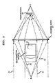
- FIG. 2 is shown a diagram of the optical portion of the signal level control solution of the invention for optical ranging on a mobile robot cart or autonomously guided vehicle.
- infrared radiation returned from a very close scattering center B will be blocked from the central portion of the Fresnel lens 17.
- light scattered from B only enters the peripheral region of the Fresnel lens and is thereby focused at C, i.e., entirely behind the photodiode 19 which is located at A.
- C i.e., entirely behind the photodiode 19 which is located at A.
- the system only responds to light from distances greater than approximately one foot from the lens 17.
- This geometric ray optic portion of the automatic signal level control provides a factor of about 20 of the total of about a thousand which is required.
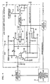
- the remaining factor of ⁇ 50 in signal level control is provided by the active electronic part of the circuit shown in FIG. 3.
- the signal 37 from the preamplifier stage 20 drives the amplifying element 31 to provide an output signal current I s at the common emitters of transistors 32 and 33.
- This current I s is small compared to the standing current I0 which flows through amplifying element 31.
- I s divides between the transistors 32 and 33 emitters in exactly the same way as does the current I0.
- This current division can be understood by first noting that the base of transistor 33 is held at a convenient fixed potential (which can be ground), while the base of transistor 32 is driven from the automatic gain control feedback circuit 38, which will be more fully detailed hereafter.
- I2 should be small when the returned optical signal level received at diode 19 is large; and the converse is also true. Moreover, this result should preferably be obtained with very little difference in overall phase shift from the one signal condition to the other.
- the overall operation of the elements of the system explained above can be appreciated by examining the diagram of FIG. 4.
- the electronic elements of the AGC arrangement as discussed in FIGS. 1 and 3 are now seen in context in FIG. 4.
- the output of the low noise integrating preamplifier stage 20 drives the base of transistor 31, while its collector current divides into I1 and I2 at the emitters of transistors 32 and 33.
- the relative magnitudes of I1 and I2 are controlled by the AGC signal which is applied to the base of transistor 32 as previously explained.
- This AGC signal comes from the gain control feedback circuitry 38 which comprises a linear rectifier which receives the same signal that drives limiter 27 (of FIG. 1).
- the linear rectifier 41 applies the rectified result to the input of the subtracter 43 which is also supplied with the desired RF reference level input 42.
- error integrator 44 which consists of operational amplifier 45 together with its feedback capacitor 46.
- the output of the error integrator in turn provides the gain control feedback signal applied to the base of transistor 32.
- the signal at the collector of transistor 33 of the automatic gain control stage is applied to the input of the tuned amplifier 24 through capacitor 47 and the grounded base stage 48.
- the AGC signal is constantly applied so as to maintain the RF amplitude level at the output of tuned amplifier 24 (of FIG. 1), and at the input to limiter 27, at a constant preassigned level. This cascaded limiting action ensures that very accurate phase measurements can be achieved.
- the gain of the gain control circuitry consisting of transistors 31, 32 and 33 is accurately proportional to magnitude of the current I2 flowing through transistor 33.
- This quantity itself is monitored by the amplifier circuit 49, thereby providing a constant linear measure of the required amplifier gain (i.e., of the optical signal strength) at terminal 50, as indicated in FIG. 4.
- This quantity in turn is constantly monitored, and range data is accumulated if and only if the electronic system is known to be operating within its 50:1 preassigned gain range.
- the amplifier gain monitor output at terminal 50 also provides very useful independent navigational information for a robot cart. This is because, since the target range is known from the phase shift measurement, the inverse square law correction can be applied for the returning radiation as a function purely of distance. Any remaining variation in signal strength, as inferred from the output signal at terminal 50, is then attributed to the effective infrared reflectivity of the target surface. In this way an infrared "brightness" map of the robot cart surroundings is continuously available. This is in addition to, and completely independent from, the "range” map provided by the optical phase shift measurement.
- the quality of the described AGC circuitry and optical signal level control is to provide very low phase shift as well as very good automatic gain control and gain magnitude monitoring throughout the signal range. Measurement has demonstrated that very low relative phase shift over the entire signal range as well as effective gain control has been achieved with the exceedingly simple, and therefore low cost, system that has been described.
Landscapes
- Engineering & Computer Science (AREA)
- Physics & Mathematics (AREA)
- Computer Networks & Wireless Communication (AREA)
- General Physics & Mathematics (AREA)
- Radar, Positioning & Navigation (AREA)
- Remote Sensing (AREA)
- Electromagnetism (AREA)
- Optical Radar Systems And Details Thereof (AREA)
- Control Of Position, Course, Altitude, Or Attitude Of Moving Bodies (AREA)
Applications Claiming Priority (2)
| Application Number | Priority Date | Filing Date | Title |
|---|---|---|---|
| US75912 | 1987-07-20 | ||
| US07/075,912 US4829172A (en) | 1987-07-20 | 1987-07-20 | Optical ranging by phase shift measurement with return signal level compensation |
Publications (3)
| Publication Number | Publication Date |
|---|---|
| EP0300663A2 true EP0300663A2 (de) | 1989-01-25 |
| EP0300663A3 EP0300663A3 (de) | 1991-01-30 |
| EP0300663B1 EP0300663B1 (de) | 1994-03-02 |
Family
ID=22128716
Family Applications (1)
| Application Number | Title | Priority Date | Filing Date |
|---|---|---|---|
| EP88306327A Expired - Lifetime EP0300663B1 (de) | 1987-07-20 | 1988-07-12 | Optische Reichweitenmessung durch Messen einer Phasenverschiebung |
Country Status (7)
| Country | Link |
|---|---|
| US (1) | US4829172A (de) |
| EP (1) | EP0300663B1 (de) |
| JP (1) | JP2618446B2 (de) |
| CA (1) | CA1288150C (de) |
| DE (1) | DE3888038T2 (de) |
| ES (1) | ES2049252T3 (de) |
| HK (1) | HK103794A (de) |
Cited By (4)
| Publication number | Priority date | Publication date | Assignee | Title |
|---|---|---|---|---|
| GB2272592A (en) * | 1992-10-29 | 1994-05-18 | Seikosha Kk | Distance measurement |
| EP1619469A1 (de) * | 2004-07-22 | 2006-01-25 | Bea S.A. | Laser Abtast- und Detektionsvorrichtung zur Detektion um automatische Türen |
| US7362224B2 (en) | 2004-07-22 | 2008-04-22 | B.E.A. S.A. | Thermally sensitive array device for presence detection around automatic doors |
| WO2017198927A1 (fr) | 2016-05-19 | 2017-11-23 | Institut Vedecom | Systeme de telemetrie optique |
Families Citing this family (20)
| Publication number | Priority date | Publication date | Assignee | Title |
|---|---|---|---|---|
| GB9020285D0 (en) * | 1990-09-17 | 1990-10-31 | Imatronic Ltd | Optical apparatus |
| IL123225A (en) * | 1992-01-12 | 1999-07-14 | Israel State | Large area movement robot |
| GB2264359B (en) * | 1992-02-20 | 1995-09-20 | Optical Metrology Ltd | Apparatus for measuring displacement by detecting phase of an optical signal |
| US5313261A (en) * | 1992-07-13 | 1994-05-17 | Applied Remote Technology Inc. | Method and apparatus for faithful gray scale representation of under water laser images |
| US5302835A (en) * | 1993-03-22 | 1994-04-12 | Imra America, Inc. | Light detection system having a polarization plane rotating means and a polarizing beamsplitter |
| US5521694A (en) * | 1994-05-10 | 1996-05-28 | Innova Laboratories, Inc. | Laser beam path profile sensor system |
| WO1996012932A1 (en) * | 1994-10-20 | 1996-05-02 | Automotive Systems Laboratory, Inc. | Optical distance measuring system having range limit detection |
| US5831719A (en) * | 1996-04-12 | 1998-11-03 | Holometrics, Inc. | Laser scanning system |
| DE19804059B4 (de) * | 1998-02-03 | 2006-02-09 | Robert Bosch Gmbh | Vorrichtung zur optischen Distanzmessung |
| JP2000111340A (ja) * | 1998-10-08 | 2000-04-18 | Topcon Corp | 測量機の光通信装置 |
| US6567762B2 (en) * | 2000-12-22 | 2003-05-20 | Agilent Technologies, Inc. | Dynamic range extension apparatus and method |
| EP1576385A2 (de) | 2002-11-26 | 2005-09-21 | James F. Munro | Vorrichtung zur präzisen distanz- und geschwindigkeitsmessungund verfahren dafür |
| EP1876415B1 (de) * | 2006-07-03 | 2010-05-12 | Trimble AB | Vermessungsinstrument und Verfahren zur Steuerung eines Vermessungsinstruments |
| EP2454619A4 (de) | 2009-07-17 | 2016-01-06 | Hewlett Packard Development Co | Nicht periodische gitterreflektoren mit fokussierungsstärke und verfahren zu ihrer herstellung |
| US20110169520A1 (en) * | 2010-01-14 | 2011-07-14 | Mks Instruments, Inc. | Apparatus for measuring minority carrier lifetime and method for using the same |
| WO2011093893A1 (en) | 2010-01-29 | 2011-08-04 | Hewlett-Packard Development Company, L.P. | Optical devices based on non-periodic sub-wavelength gratings |
| WO2012105945A1 (en) * | 2011-01-31 | 2012-08-09 | Hewlett-Packard Development Company, L.P. | Apparatus and method for performing spectroscopy |
| DE102016106154B3 (de) * | 2016-04-05 | 2017-02-16 | Sick Ag | Optoelektronischer Sensor und Verfahren zur Erfassung und Entfernungsbestimmung eines Objekts |
| CN107356929B (zh) * | 2016-08-29 | 2020-07-28 | 北醒(北京)光子科技有限公司 | 一种快速扫描探测方法 |
| US12372616B1 (en) * | 2022-07-22 | 2025-07-29 | The United States Of America As Represented By The Secretary Of The Navy | Near-IR emulator for complex electromagnetic structures |
Family Cites Families (5)
| Publication number | Priority date | Publication date | Assignee | Title |
|---|---|---|---|---|
| US3779645A (en) * | 1970-05-20 | 1973-12-18 | Nippon Kogaku Kk | Distance measuring device |
| US4346989A (en) * | 1976-11-18 | 1982-08-31 | Hewlett-Packard Company | Surveying instrument |
| US4453825A (en) * | 1979-12-07 | 1984-06-12 | Hewlett-Packard Company | Distance transducer |
| FR2556088B1 (fr) * | 1983-12-01 | 1988-09-09 | Rech Const Electro Et | Procede pour la mesure de distance entre deux points d'observation sur la base du temps de propagation aller-retour d'un signal entre ces deux points, adapte en particulier aux turbulences du milieu de propagation, et telemetre mettant en oeuvre ce procede |
| SE442557B (sv) * | 1984-05-21 | 1986-01-13 | Geotronics Ab | Anordning for att halla ett instrument inriktat mot en rorlig reflektor |
-
1987
- 1987-07-20 US US07/075,912 patent/US4829172A/en not_active Expired - Lifetime
-
1988
- 1988-05-31 CA CA000568165A patent/CA1288150C/en not_active Expired - Lifetime
- 1988-07-12 EP EP88306327A patent/EP0300663B1/de not_active Expired - Lifetime
- 1988-07-12 ES ES88306327T patent/ES2049252T3/es not_active Expired - Lifetime
- 1988-07-12 DE DE3888038T patent/DE3888038T2/de not_active Expired - Fee Related
- 1988-07-20 JP JP63179323A patent/JP2618446B2/ja not_active Expired - Lifetime
-
1994
- 1994-09-29 HK HK103794A patent/HK103794A/en not_active IP Right Cessation
Cited By (10)
| Publication number | Priority date | Publication date | Assignee | Title |
|---|---|---|---|---|
| GB2272592A (en) * | 1992-10-29 | 1994-05-18 | Seikosha Kk | Distance measurement |
| US5444511A (en) * | 1992-10-29 | 1995-08-22 | Seikosha Co., Ltd. | Distance measuring device for camera |
| EP1619469A1 (de) * | 2004-07-22 | 2006-01-25 | Bea S.A. | Laser Abtast- und Detektionsvorrichtung zur Detektion um automatische Türen |
| EP1832866A2 (de) | 2004-07-22 | 2007-09-12 | Bea S.A. | Türsensorsystem zur Erfassung eines Zielobjekts |
| US7349074B2 (en) | 2004-07-22 | 2008-03-25 | B.E.A. Sa | Laser scanning and sensing device for detection around automatic doors |
| US7362224B2 (en) | 2004-07-22 | 2008-04-22 | B.E.A. S.A. | Thermally sensitive array device for presence detection around automatic doors |
| US7446862B2 (en) | 2004-07-22 | 2008-11-04 | B.E.A.S.A. | Door sensor system for detecting a target object |
| WO2017198927A1 (fr) | 2016-05-19 | 2017-11-23 | Institut Vedecom | Systeme de telemetrie optique |
| FR3051560A1 (fr) * | 2016-05-19 | 2017-11-24 | Inst Vedecom | Systeme de telemetrie optique |
| US11255971B2 (en) | 2016-05-19 | 2022-02-22 | Institut Vedecom | Optical telemetry system |
Also Published As
| Publication number | Publication date |
|---|---|
| EP0300663B1 (de) | 1994-03-02 |
| EP0300663A3 (de) | 1991-01-30 |
| JPS6439575A (en) | 1989-02-09 |
| JP2618446B2 (ja) | 1997-06-11 |
| DE3888038T2 (de) | 1994-09-08 |
| ES2049252T3 (es) | 1994-04-16 |
| US4829172A (en) | 1989-05-09 |
| CA1288150C (en) | 1991-08-27 |
| HK103794A (en) | 1994-10-07 |
| DE3888038D1 (de) | 1994-04-07 |
Similar Documents
| Publication | Publication Date | Title |
|---|---|---|
| EP0300663B1 (de) | Optische Reichweitenmessung durch Messen einer Phasenverschiebung | |
| Miller et al. | An optical rangefinder for autonomous robot cart navigation | |
| US3815994A (en) | System and method for measuring distance | |
| JP3622969B2 (ja) | 距離、速度、加速度を測定することができるレーザ・センサ | |
| US4051329A (en) | An optical information recording system in which the energy when transmitted to the recording layer is constant | |
| US5291031A (en) | Optical phase difference range determination in liquid level sensor | |
| AU719134B2 (en) | Device for calibrating distance-measuring apparatuses | |
| EP0640846B1 (de) | Optisches Messgerät | |
| CN210142193U (zh) | 一种测距装置、移动平台 | |
| US4511248A (en) | Active electro-optical distance detection methods and devices | |
| US12055664B2 (en) | Dual photodiode light detection and ranging | |
| CN112219330A (zh) | 一种激光接收电路及测距装置、移动平台 | |
| US5068527A (en) | Wide range fiber optical displacement sensor | |
| US11867814B1 (en) | Techniques for driving a laser diode in a LIDAR system | |
| US6844936B2 (en) | Device for the non-contacting measurement of an object to be measured, particularly for distance and/or vibration measurement | |
| WO2020195333A1 (ja) | 距離計測回路、測距装置および移動体 | |
| US6549058B1 (en) | Signal processing circuits for multiplication or division of analog signals and optical triangulation distance measurement system and method incorporating same | |
| RU2059199C1 (ru) | Оптико-электронное устройство для измерения пространственного положения объекта | |
| JP3241857B2 (ja) | 光学式距離計 | |
| US20230393281A1 (en) | Systems and Methods for Flight Navigation Using Lidar Devices | |
| Bury | Proximity sensing for robots | |
| JPS59228103A (ja) | 変位量検出装置 | |
| RU2167394C2 (ru) | Оптико-электронный датчик перемещения | |
| Bazin et al. | General characterization of laser range-finder optical heads | |
| Ahola et al. | A fast time-of-flight distance sensor for industrial applications |
Legal Events
| Date | Code | Title | Description |
|---|---|---|---|
| PUAI | Public reference made under article 153(3) epc to a published international application that has entered the european phase |
Free format text: ORIGINAL CODE: 0009012 |
|
| AK | Designated contracting states |
Kind code of ref document: A2 Designated state(s): DE ES FR GB IT NL SE |
|
| PUAL | Search report despatched |
Free format text: ORIGINAL CODE: 0009013 |
|
| AK | Designated contracting states |
Kind code of ref document: A3 Designated state(s): DE ES FR GB IT NL SE |
|
| 17P | Request for examination filed |
Effective date: 19910712 |
|
| 17Q | First examination report despatched |
Effective date: 19921203 |
|
| GRAA | (expected) grant |
Free format text: ORIGINAL CODE: 0009210 |
|
| AK | Designated contracting states |
Kind code of ref document: B1 Designated state(s): DE ES FR GB IT NL SE |
|
| ITF | It: translation for a ep patent filed | ||
| ET | Fr: translation filed | ||
| REF | Corresponds to: |
Ref document number: 3888038 Country of ref document: DE Date of ref document: 19940407 |
|
| REG | Reference to a national code |
Ref country code: ES Ref legal event code: FG2A Ref document number: 2049252 Country of ref document: ES Kind code of ref document: T3 |
|
| RAP4 | Party data changed (patent owner data changed or rights of a patent transferred) |
Owner name: AT&T CORP. |
|
| PLBE | No opposition filed within time limit |
Free format text: ORIGINAL CODE: 0009261 |
|
| STAA | Information on the status of an ep patent application or granted ep patent |
Free format text: STATUS: NO OPPOSITION FILED WITHIN TIME LIMIT |
|
| EAL | Se: european patent in force in sweden |
Ref document number: 88306327.3 |
|
| PG25 | Lapsed in a contracting state [announced via postgrant information from national office to epo] |
Ref country code: NL Effective date: 19950201 |
|
| 26N | No opposition filed | ||
| NLV4 | Nl: lapsed or anulled due to non-payment of the annual fee | ||
| REG | Reference to a national code |
Ref country code: GB Ref legal event code: IF02 |
|
| PGFP | Annual fee paid to national office [announced via postgrant information from national office to epo] |
Ref country code: FR Payment date: 20020619 Year of fee payment: 15 |
|
| PGFP | Annual fee paid to national office [announced via postgrant information from national office to epo] |
Ref country code: GB Payment date: 20020621 Year of fee payment: 15 |
|
| PGFP | Annual fee paid to national office [announced via postgrant information from national office to epo] |
Ref country code: SE Payment date: 20020625 Year of fee payment: 15 |
|
| PGFP | Annual fee paid to national office [announced via postgrant information from national office to epo] |
Ref country code: ES Payment date: 20020710 Year of fee payment: 15 |
|
| PGFP | Annual fee paid to national office [announced via postgrant information from national office to epo] |
Ref country code: DE Payment date: 20020916 Year of fee payment: 15 |
|
| PG25 | Lapsed in a contracting state [announced via postgrant information from national office to epo] |
Ref country code: GB Free format text: LAPSE BECAUSE OF NON-PAYMENT OF DUE FEES Effective date: 20030712 |
|
| PG25 | Lapsed in a contracting state [announced via postgrant information from national office to epo] |
Ref country code: SE Free format text: LAPSE BECAUSE OF NON-PAYMENT OF DUE FEES Effective date: 20030713 |
|
| PG25 | Lapsed in a contracting state [announced via postgrant information from national office to epo] |
Ref country code: ES Free format text: LAPSE BECAUSE OF NON-PAYMENT OF DUE FEES Effective date: 20030714 |
|
| PG25 | Lapsed in a contracting state [announced via postgrant information from national office to epo] |
Ref country code: DE Free format text: LAPSE BECAUSE OF NON-PAYMENT OF DUE FEES Effective date: 20040203 |
|
| EUG | Se: european patent has lapsed | ||
| GBPC | Gb: european patent ceased through non-payment of renewal fee |
Effective date: 20030712 |
|
| PG25 | Lapsed in a contracting state [announced via postgrant information from national office to epo] |
Ref country code: FR Free format text: LAPSE BECAUSE OF NON-PAYMENT OF DUE FEES Effective date: 20040331 |
|
| REG | Reference to a national code |
Ref country code: FR Ref legal event code: ST |
|
| REG | Reference to a national code |
Ref country code: ES Ref legal event code: FD2A Effective date: 20030714 |
|
| PG25 | Lapsed in a contracting state [announced via postgrant information from national office to epo] |
Ref country code: IT Free format text: LAPSE BECAUSE OF NON-PAYMENT OF DUE FEES;WARNING: LAPSES OF ITALIAN PATENTS WITH EFFECTIVE DATE BEFORE 2007 MAY HAVE OCCURRED AT ANY TIME BEFORE 2007. THE CORRECT EFFECTIVE DATE MAY BE DIFFERENT FROM THE ONE RECORDED. Effective date: 20050712 |