EP0300742A2 - Apparat zum automatischen Aufrollen und Bandagieren von aus einem Dokument-Vervielfältigungssystem ausgegebenen Blättern - Google Patents
Apparat zum automatischen Aufrollen und Bandagieren von aus einem Dokument-Vervielfältigungssystem ausgegebenen Blättern Download PDFInfo
- Publication number
- EP0300742A2 EP0300742A2 EP88306616A EP88306616A EP0300742A2 EP 0300742 A2 EP0300742 A2 EP 0300742A2 EP 88306616 A EP88306616 A EP 88306616A EP 88306616 A EP88306616 A EP 88306616A EP 0300742 A2 EP0300742 A2 EP 0300742A2
- Authority
- EP
- European Patent Office
- Prior art keywords
- tape
- sheet
- rolled
- roll
- sheets
- Prior art date
- Legal status (The legal status is an assumption and is not a legal conclusion. Google has not performed a legal analysis and makes no representation as to the accuracy of the status listed.)
- Withdrawn
Links
- 238000005096 rolling process Methods 0.000 title claims abstract description 7
- 239000000853 adhesive Substances 0.000 claims description 5
- 230000001070 adhesive effect Effects 0.000 claims description 5
- 239000000758 substrate Substances 0.000 claims description 5
- 239000002390 adhesive tape Substances 0.000 claims description 3
- 230000000694 effects Effects 0.000 claims description 3
- 238000000926 separation method Methods 0.000 claims 1
- 108091008695 photoreceptors Proteins 0.000 description 6
- 238000004140 cleaning Methods 0.000 description 2
- 238000004519 manufacturing process Methods 0.000 description 2
- 239000000463 material Substances 0.000 description 2
- 239000002245 particle Substances 0.000 description 2
- 238000010276 construction Methods 0.000 description 1
- 239000000356 contaminant Substances 0.000 description 1
- 230000003111 delayed effect Effects 0.000 description 1
- 239000000835 fiber Substances 0.000 description 1
- 239000006260 foam Substances 0.000 description 1
- 238000009434 installation Methods 0.000 description 1
- 238000000034 method Methods 0.000 description 1
- 239000000203 mixture Substances 0.000 description 1
- 238000007789 sealing Methods 0.000 description 1
- 238000004804 winding Methods 0.000 description 1
Images

Classifications
-
- G—PHYSICS
- G03—PHOTOGRAPHY; CINEMATOGRAPHY; ANALOGOUS TECHNIQUES USING WAVES OTHER THAN OPTICAL WAVES; ELECTROGRAPHY; HOLOGRAPHY
- G03G—ELECTROGRAPHY; ELECTROPHOTOGRAPHY; MAGNETOGRAPHY
- G03G15/00—Apparatus for electrographic processes using a charge pattern
- G03G15/65—Apparatus which relate to the handling of copy material
- G03G15/6552—Means for discharging uncollated sheet copy material, e.g. discharging rollers, exit trays
-
- B—PERFORMING OPERATIONS; TRANSPORTING
- B65—CONVEYING; PACKING; STORING; HANDLING THIN OR FILAMENTARY MATERIAL
- B65H—HANDLING THIN OR FILAMENTARY MATERIAL, e.g. SHEETS, WEBS, CABLES
- B65H18/00—Winding webs
- B65H18/08—Web-winding mechanisms
- B65H18/14—Mechanisms in which power is applied to web roll, e.g. to effect continuous advancement of web
- B65H18/16—Mechanisms in which power is applied to web roll, e.g. to effect continuous advancement of web by friction roller
-
- B—PERFORMING OPERATIONS; TRANSPORTING
- B65—CONVEYING; PACKING; STORING; HANDLING THIN OR FILAMENTARY MATERIAL
- B65H—HANDLING THIN OR FILAMENTARY MATERIAL, e.g. SHEETS, WEBS, CABLES
- B65H19/00—Changing the web roll
- B65H19/22—Changing the web roll in winding mechanisms or in connection with winding operations
- B65H19/29—Securing the trailing end of the wound web to the web roll
-
- G—PHYSICS
- G03—PHOTOGRAPHY; CINEMATOGRAPHY; ANALOGOUS TECHNIQUES USING WAVES OTHER THAN OPTICAL WAVES; ELECTROGRAPHY; HOLOGRAPHY
- G03G—ELECTROGRAPHY; ELECTROPHOTOGRAPHY; MAGNETOGRAPHY
- G03G15/00—Apparatus for electrographic processes using a charge pattern
- G03G15/65—Apparatus which relate to the handling of copy material
- G03G15/6588—Apparatus which relate to the handling of copy material characterised by the copy material, e.g. postcards, large copies, multi-layered materials, coloured sheet material
- G03G15/6594—Apparatus which relate to the handling of copy material characterised by the copy material, e.g. postcards, large copies, multi-layered materials, coloured sheet material characterised by the format or the thickness, e.g. endless forms
-
- B—PERFORMING OPERATIONS; TRANSPORTING
- B65—CONVEYING; PACKING; STORING; HANDLING THIN OR FILAMENTARY MATERIAL
- B65H—HANDLING THIN OR FILAMENTARY MATERIAL, e.g. SHEETS, WEBS, CABLES
- B65H2701/00—Handled material; Storage means
- B65H2701/10—Handled articles or webs
- B65H2701/18—Form of handled article or web
- B65H2701/184—Wound packages
- B65H2701/1846—Parts concerned
-
- G—PHYSICS
- G03—PHOTOGRAPHY; CINEMATOGRAPHY; ANALOGOUS TECHNIQUES USING WAVES OTHER THAN OPTICAL WAVES; ELECTROGRAPHY; HOLOGRAPHY
- G03G—ELECTROGRAPHY; ELECTROPHOTOGRAPHY; MAGNETOGRAPHY
- G03G2215/00—Apparatus for electrophotographic processes
- G03G2215/00362—Apparatus for electrophotographic processes relating to the copy medium handling
- G03G2215/00367—The feeding path segment where particular handling of the copy medium occurs, segments being adjacent and non-overlapping. Each segment is identified by the most downstream point in the segment, so that for instance the segment labelled "Fixing device" is referring to the path between the "Transfer device" and the "Fixing device"
- G03G2215/00417—Post-fixing device
- G03G2215/00426—Post-treatment device adding qualities to the copy medium product
-
- G—PHYSICS
- G03—PHOTOGRAPHY; CINEMATOGRAPHY; ANALOGOUS TECHNIQUES USING WAVES OTHER THAN OPTICAL WAVES; ELECTROGRAPHY; HOLOGRAPHY
- G03G—ELECTROGRAPHY; ELECTROPHOTOGRAPHY; MAGNETOGRAPHY
- G03G2215/00—Apparatus for electrophotographic processes
- G03G2215/00362—Apparatus for electrophotographic processes relating to the copy medium handling
- G03G2215/00443—Copy medium
- G03G2215/00451—Paper
- G03G2215/00464—Non-standard format
- G03G2215/00468—Large sized, e.g. technical plans
-
- G—PHYSICS
- G03—PHOTOGRAPHY; CINEMATOGRAPHY; ANALOGOUS TECHNIQUES USING WAVES OTHER THAN OPTICAL WAVES; ELECTROGRAPHY; HOLOGRAPHY
- G03G—ELECTROGRAPHY; ELECTROPHOTOGRAPHY; MAGNETOGRAPHY
- G03G2215/00—Apparatus for electrophotographic processes
- G03G2215/00362—Apparatus for electrophotographic processes relating to the copy medium handling
- G03G2215/00789—Adding properties or qualities to the copy medium
- G03G2215/00873—Tape adding means
Definitions
- the present invention relates to an apparatus for automatically rolling up shets, for example copy sheets from the output station of a document reproduction system.
- US-A-2,849,191 discloses an apparatus for winding paper material into rolls.
- the apparatus includes two input rollers and two roll-up stations where the sheets are rolled within a central aperture formed between rolled sets. Upon completing the roll-up operation, the paper rolls automatically fall into a container.
- US-A-3,052,073 shows a cluster of rollers which form a space therebetween in which sheets are wound. As the rolled sheet diameter expands, bottom rollers are moved away to allow rolled-up sheets to be removed.
- US-A-4,381,211 to Nechay discloses a label carrying web transport wherein labels 110 are optically registered by a scanner assembly 50 which emits a signal, thereby setting into motion an apparatus which regulates intermittent web motion and controls the advance of the labels.
- US-A-4,248,655 to Kerwin discloses a control system for a moving web wherein a series of indicia on the web are sensed and a first signal indicative of an indicium is generated. A series of moving articles is sensed and a second signal indicative of a moving article is generated. The disparity between the sensed indicium and moving article is then calculated, and a speed adjustment of the web and moving articles is made to obtain a corrected relative position of indicium and moving article.
- EP-A-106,167 discloses an apparatus for securing the tail portion of a rolled product with labels 30a and 30b and comprising sensors 70 and 72, and feed rollers 12 and 14.
- US-A-4,397,710 to Gaylord discloses a machine for applying labels to a cylindrical article.
- the machine comprises a sensor assembly 34 which responds to dark sensor mark 22 associated with each label to activate both web advancement and placement of the labels onto the cylindrical articles.
- the present invention is therefore directed to an apparatus for automatically rolling up and taping output sheets including, in combination: means for accepting sheets and feeding them into a roll-up assembly, the roll-up assembly incorporating a plurality of roller members which cooperate to wind the sheets into a spiral form; and means for securing the sheets in a final rolled-up configuration, said means including a tape dispensing mechanism periodically actuated to dispense a tape segment across the trailing edge of the rolled-up sheet.
- Machine 8 has a suitable frame 12 on which the machine xerographic components are operatively supported.
- the machine xerographic components include a recording member, shown here in the form of a rotatable drum 14 having a photoconductive surface.
- a recording member shown here in the form of a rotatable drum 14 having a photoconductive surface.
- Other photoreceptor types such as a belt or web may instead be contemplated.
- charge corotron 18 for placing a uniform charge on the photoconductive surface of photoreceptor 14, an exposure station 20 where the previously charged photoconductive surface is exposed to image rays of the document 9 being copied or reproduced, development station 24 where the latent electrostatic image created on the photoconductive surface is developed by toner, transfer station 28 with transfer corotrons 29, 30 for transferring the developed image to a suitable copy substrate material such as a copy sheet 32 brought forward in timed relation with the developed image on photoconductive surface and cleaning station 34 for removing leftover developer from the photoconductive surface.
- a suitable copy substrate material such as a copy sheet 32 brought forward in timed relation with the developed image on photoconductive surface
- cleaning station 34 for removing leftover developer from the photoconductive surface.
- Copy sheets 32 are brought forward to transfer station 28 by feed roll pair 40 and sheet guides 42, 43. Following transfer, the sheet 32 is carried forward to a fusing station 44 where the toner image is fixed by fusing roll 45 in cooperation with a biased flexible web 47. Fusing roll 45 is heated by a suitable heater such as lamp 46 disposed within the interior of roll 45. After fixing, the copy sheet 32 enters the document roll-up apparatus 49 whose operation is described in detail below.
- transparent platen 50 supports the document 9 as the document is moved past a scan point 52 by a constant velocity type transport 54.
- scan point 52 is, in effect, a scan line extending across the width of platen 50 at a desired point where the document is scanned line-by-line.
- Transport 54 has input and output document feed roll pairs 55, 56 respectively on each side of scan point 52 for moving document 9 across platen 50 at a predetermined speed.
- Exposure lamp 58 is provided to illuminate a strip-like area of platen 50 at scan point 52. The image rays from the document line scanned are transmitted by a gradient index fiber lens array 60 to exposure station 20 to expose the photoconductive surface of the moving photoreceptor 14.
- Developing station 24 includes a developer housing 65, the lower part of which forms a sump 66 for holding a quantity of developer.
- developer comprises a mixture of larger carrier particles and smaller toner or ink particles.
- a rotatable magnetic brush developer roll 70 is disposed in predetermined operative relation to the photoconductive surface. In developer housing 65, roll 70 serving to bring developer from sump 66 into developing relation with photoreceptor 14 to develop the latent electrostatic images formed on the photoconductive surface thereof.
- documents 9 represent large (up to about 92 cm) engineering drawings.
- the width of the photoreceptor, and the dimension of the developing transfer cleaning and fusing stations are of like dimension.
- Feed roller sets 72 and 74 comprise a plurality of rollers, a preferred number being two, which are driven in the indicated direction.
- the rollers are mounted on shafts 76, 78 which are driven by drive motors (not shown).
- the sheet is guided by baffle members 80, 82, 84 and 86 all of which present relatively smooth surfaces to the sheets thereacross.
- Baffle member 82 has an upward inclination 85 at the left end with a straight section 86 from left of center position to the right end (viewed from Fig.
- Baffle member 80 comprises a flat section which forms a parallel guideway with section 86.
- Baffle member 84 has a straight left section 90 and a curved right section 92. Curved sections 88 and 92 enclose a central, roll-up area 94 therebetween.
- Baffle members 88 and 92 are further characterized as having a plurality of apertures formed at intervals along their length. These apertures are of sufficient width and length to accommodate a portion of roller sets 100, 102 and 104 seated therein. As shown, a small chord of each roller protrudes a short distance into the interior of central roll-up area 94.
- Roller sets 100, 102, 104 are mounted on shafts and driven in the indicated direction by motor means (not shown).
- Baffle member 92 and roller sets 102, 104 are further characterized as forming an assembly 156 which is pivotable downward in a clockwise direction, about point 105 to the position shown in Figure 6.
- roller set 100 The sheet, now being propelled by feed roll set 72, 74 and roller sets 102, 104 continues to slide along the surface of baffle members 92 and 88, until it encounters roller set 100.
- rollers contribute to the continued motion of the sheet which has now assumed a spiraling motion.
- the leading edge of the sheet completes a complete spiral revolution as the leading edge contacts an intermediate portion of the still advancing copy sheet.
- the first "ring" of the rolled up document has been established.
- the roll-up, spiraling action will continue in the same manner with the roll being slightly compressed inward with the addition of each new "ring” following a complete revolution.
- the roller sets are of soft foam construction to allow for expanded diameter of additional "rings".
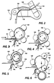
- tape-dispensing assembly 130 the assembly is seen to consist of tape-dispensing supply roll 132 containing a supply of wound-up adhesive tape 134.
- Tape 134 consists of a roll of continuous 25 mm wide release liner 136 upon which are adhered individual strips of tape 138.
- the tape segments are 210 mm in length and completely encircle the circumferential outer surface of the rolled up sheet.
- Other suitable lengths of tape segment may be used, for example shorter lengths such as about 76 mm which secure the trailing edge of the rolled up sheet to the roll, or longer lengths for rolled up sheets having a roll of greater diameter.
- the top surface of the tape presents an adhesive surface to the rolled-up copy sheet, as will be seen below.
- the tape incorporates peelable adhesive with a non-glued edge to facilitate subsequent removal from the copy.
- the tape is withdrawn from supply roll 132, advanced through guideway 140 and bent around the edge of strip plate 142.
- Strip plate 142 shown enlarged in Figure 2 incorporates an edge 144.
- Edge 144 functions to cause a clean stripping of liner from the top segments but is not sharp enough to cause tape or liner tearing.
- the edge has a radius of 0.76 mm.
- Liner 136 is then threaded between pinch roll 146, drive roll 153, tension roll 150 and liner take-up roll 152. The tape segments are discarded corresponding to the threaded liner.
- FIG. 1 the trailing edge of a copy sheet 32 is sensed by photosensor 111 (Fig. 1) and a timed signal is sent by appropriate control circuitry to a motor (not shown) which drives roll 153 in the indicated direction.
- Figure 3 shows the output sheet being rolled-up prior to tape dispensing.
- Rollers 146, 150 serve to pull the tape 134 taut around edge 144 of strip plate 142. This causes the leading edge of a relatively rigid tape segment 138 to continue forward guided by baffle 148 until it engages the surface of rolled-up sheet 32 (fig. 4) adjacent the trailing edge. Approximately 38 mm of the tape segment 138 will adhere to the rolled-up sheet surface before encountering the training edge seam (Fig. 5).
- the tape As the roll-up action continues, the tape, advancing in the same rotational direction as the copy sheet, overlaps the trailing edge (Fig. 5). During continuing sheet rotation, the tape is continually pressed into secure contact with the rolled-up sheet through combined action of the roller sets and frictional movement along the baffle walls. The remaining portion of the tape continues to adhere to the surface of the rotating, scrolled sheet until it overlaps that portion of the tape initially adhering to the sheet side. This complete wrap-around of the tape constitutes an effective sealing strip which is not affected by contaminants, such as fuser oil, which may have been deposited on the sheet surface.
- Baffle 148 incorporates a sensor 154 adjacent the tape edge.
- the sensor detects the trailing edge of the tape segment 138 and sends an appropriate, delayed signal to the driver motor of drive roll 153, stopping further tape movement.
- the rolled-up, sealed sheet can now be removed by pivoting baffle/roller assembly 156 counterclockwise to the position shown in Figure 6, allowing the rolled-up copy to drop downward into a receptacle or be removed manually.
Landscapes
- Physics & Mathematics (AREA)
- General Physics & Mathematics (AREA)
- Discharge By Other Means (AREA)
- Adhesive Tape Dispensing Devices (AREA)
- Replacement Of Web Rolls (AREA)
Applications Claiming Priority (4)
| Application Number | Priority Date | Filing Date | Title |
|---|---|---|---|
| US7545187A | 1987-07-20 | 1987-07-20 | |
| US75451 | 1987-07-20 | ||
| US10400987A | 1987-10-02 | 1987-10-02 | |
| US104009 | 1987-10-02 |
Publications (2)
| Publication Number | Publication Date |
|---|---|
| EP0300742A2 true EP0300742A2 (de) | 1989-01-25 |
| EP0300742A3 EP0300742A3 (de) | 1990-10-31 |
Family
ID=26756878
Family Applications (1)
| Application Number | Title | Priority Date | Filing Date |
|---|---|---|---|
| EP19880306616 Withdrawn EP0300742A3 (de) | 1987-07-20 | 1988-07-20 | Apparat zum automatischen Aufrollen und Bandagieren von aus einem Dokument-Vervielfältigungssystem ausgegebenen Blättern |
Country Status (1)
| Country | Link |
|---|---|
| EP (1) | EP0300742A3 (de) |
Cited By (5)
| Publication number | Priority date | Publication date | Assignee | Title |
|---|---|---|---|---|
| US4909015A (en) * | 1987-10-21 | 1990-03-20 | Ferag Ag | Apparatus for the fabrication of portable tubular-shaped packages formed of printed products |
| EP0453091A1 (de) * | 1990-03-16 | 1991-10-23 | Xerox Corporation | Vorrichtung zum Aufwickeln von Dokumenten |
| GB2270902A (en) * | 1992-08-31 | 1994-03-30 | Fuji Xerox Co Ltd | Recorded sheet processing unit for image forming apparatus. |
| EP0767122A1 (de) * | 1995-10-05 | 1997-04-09 | Elsner Engineering Works Inc | Wickelrolle mit Verschlussstreifen |
| US5980676A (en) * | 1991-12-16 | 1999-11-09 | Xerox Corporation | Method of multiple copy sets distribution with temporarily taped set distinctions |
Family Cites Families (2)
| Publication number | Priority date | Publication date | Assignee | Title |
|---|---|---|---|---|
| US3052073A (en) * | 1959-06-10 | 1962-09-04 | Reichel & Drews Inc | Strip rolling and wrapping machine |
| DE8533092U1 (de) * | 1985-11-25 | 1986-07-17 | Bardowicker Lichtpausmaschinen GmbH, 2123 Bardowick | Papieraufwickelmaschine |
-
1988
- 1988-07-20 EP EP19880306616 patent/EP0300742A3/de not_active Withdrawn
Cited By (8)
| Publication number | Priority date | Publication date | Assignee | Title |
|---|---|---|---|---|
| US4909015A (en) * | 1987-10-21 | 1990-03-20 | Ferag Ag | Apparatus for the fabrication of portable tubular-shaped packages formed of printed products |
| EP0453091A1 (de) * | 1990-03-16 | 1991-10-23 | Xerox Corporation | Vorrichtung zum Aufwickeln von Dokumenten |
| US5980676A (en) * | 1991-12-16 | 1999-11-09 | Xerox Corporation | Method of multiple copy sets distribution with temporarily taped set distinctions |
| GB2270902A (en) * | 1992-08-31 | 1994-03-30 | Fuji Xerox Co Ltd | Recorded sheet processing unit for image forming apparatus. |
| US5466328A (en) * | 1992-08-31 | 1995-11-14 | Fuji Xerox Co., Ltd. | Recorded sheet processing unit for image forming apparatus |
| GB2270902B (en) * | 1992-08-31 | 1996-04-24 | Fuji Xerox Co Ltd | Recorded sheet processing unit for image forming apparatus |
| DE4329307C2 (de) * | 1992-08-31 | 2002-04-04 | Fuji Xerox Co Ltd | Druckblatt-Verarbeitungseinheit für eine Bilderzeugungseinrichtung |
| EP0767122A1 (de) * | 1995-10-05 | 1997-04-09 | Elsner Engineering Works Inc | Wickelrolle mit Verschlussstreifen |
Also Published As
| Publication number | Publication date |
|---|---|
| EP0300742A3 (de) | 1990-10-31 |
Similar Documents
| Publication | Publication Date | Title |
|---|---|---|
| US3862802A (en) | Sheet reversing apparatus and a duplex reproducing apparatus employing same | |
| US5768675A (en) | On-demand narrow web electrophotographic printer | |
| US4838497A (en) | Apparatus for automatically rolling up media sheets | |
| GB1587735A (en) | Image forming apparatus | |
| US4784345A (en) | Apparatus for automatically rolling up output sheets from a document reproduction system | |
| EP0291319B1 (de) | Abstreiffinger-Mechanismus | |
| US4110035A (en) | Cleaning system for an electrophotographic printing machine | |
| US4277160A (en) | Electrostatic printer | |
| US4013359A (en) | Electrostatic copier including means for detaching paper from a photoconductor | |
| US5016833A (en) | Document roll-up system | |
| US3796486A (en) | Programming control system for printing machine | |
| EP0010848B1 (de) | Elektrophotographisches Gerät mit einem ersetzbaren photoleitfähigen Aufzeichnungsband | |
| EP0124375B1 (de) | Elektrostatographisches Gerät | |
| US3100112A (en) | Document feed mechanism | |
| JPH06127729A (ja) | 画像形成装置の無端ベルトにおける速度検知ロールの清掃装置 | |
| US6066082A (en) | Paper sheet folding apparatus | |
| EP1128227A2 (de) | Elektrostatographisches Bilderzeugungsgerät und Verfahren zur Verminderung der Übertragungsrollen-Artefakten | |
| JP3527601B2 (ja) | 画像形成装置のベルト搬送装置 | |
| US3995951A (en) | Sheet feeding apparatus and reproducing machine | |
| GB2150885A (en) | Image forming apparatus with laminating mechanism | |
| JP3198798B2 (ja) | 画像形成装置 | |
| USRE29514E (en) | Programming control system for printing machine | |
| CA1127586A (en) | Document registering and feeding apparatus | |
| JP2533477Y2 (ja) | 転写装置 | |
| JP3256000B2 (ja) | 画像形成装置 |
Legal Events
| Date | Code | Title | Description |
|---|---|---|---|
| PUAI | Public reference made under article 153(3) epc to a published international application that has entered the european phase |
Free format text: ORIGINAL CODE: 0009012 |
|
| AK | Designated contracting states |
Kind code of ref document: A2 Designated state(s): DE FR GB |
|
| PUAL | Search report despatched |
Free format text: ORIGINAL CODE: 0009013 |
|
| RHK1 | Main classification (correction) |
Ipc: B65H 19/29 |
|
| AK | Designated contracting states |
Kind code of ref document: A3 Designated state(s): DE FR GB |
|
| STAA | Information on the status of an ep patent application or granted ep patent |
Free format text: STATUS: THE APPLICATION HAS BEEN WITHDRAWN |
|
| 18W | Application withdrawn |
Withdrawal date: 19910615 |
|
| R18W | Application withdrawn (corrected) |
Effective date: 19910615 |