EP0300780B1 - Apparat zum Setzen eines Filmbands unter Spannung - Google Patents
Apparat zum Setzen eines Filmbands unter Spannung Download PDFInfo
- Publication number
- EP0300780B1 EP0300780B1 EP88306689A EP88306689A EP0300780B1 EP 0300780 B1 EP0300780 B1 EP 0300780B1 EP 88306689 A EP88306689 A EP 88306689A EP 88306689 A EP88306689 A EP 88306689A EP 0300780 B1 EP0300780 B1 EP 0300780B1
- Authority
- EP
- European Patent Office
- Prior art keywords
- film
- web
- rollers
- roller
- folded web
- Prior art date
- Legal status (The legal status is an assumption and is not a legal conclusion. Google has not performed a legal analysis and makes no representation as to the accuracy of the status listed.)
- Expired - Lifetime
Links
- 238000004806 packaging method and process Methods 0.000 claims description 35
- 238000007789 sealing Methods 0.000 claims description 24
- 238000000034 method Methods 0.000 claims description 10
- 239000000463 material Substances 0.000 claims description 2
- 238000000151 deposition Methods 0.000 claims 1
- 230000037303 wrinkles Effects 0.000 description 3
- 230000006835 compression Effects 0.000 description 1
- 238000007906 compression Methods 0.000 description 1
- 239000002537 cosmetic Substances 0.000 description 1
- 235000013365 dairy product Nutrition 0.000 description 1
- 239000003814 drug Substances 0.000 description 1
- 230000000694 effects Effects 0.000 description 1
- 235000013305 food Nutrition 0.000 description 1
- 239000000155 melt Substances 0.000 description 1
- 235000014101 wine Nutrition 0.000 description 1
Images


Classifications
-
- B—PERFORMING OPERATIONS; TRANSPORTING
- B65—CONVEYING; PACKING; STORING; HANDLING THIN OR FILAMENTARY MATERIAL
- B65B—MACHINES, APPARATUS OR DEVICES FOR, OR METHODS OF, PACKAGING ARTICLES OR MATERIALS; UNPACKING
- B65B9/00—Enclosing successive articles, or quantities of material, e.g. liquids or semiliquids, in flat, folded, or tubular webs of flexible sheet material; Subdividing filled flexible tubes to form packages
- B65B9/10—Enclosing successive articles, or quantities of material, in preformed tubular webs, or in webs formed into tubes around filling nozzles, e.g. extruded tubular webs
- B65B9/20—Enclosing successive articles, or quantities of material, in preformed tubular webs, or in webs formed into tubes around filling nozzles, e.g. extruded tubular webs the webs being formed into tubes in situ around the filling nozzles
- B65B9/2042—Means for altering the cross-section of the tube filling opening prior to transversal sealing, e.g. tube spreading devices
-
- B—PERFORMING OPERATIONS; TRANSPORTING
- B65—CONVEYING; PACKING; STORING; HANDLING THIN OR FILAMENTARY MATERIAL
- B65B—MACHINES, APPARATUS OR DEVICES FOR, OR METHODS OF, PACKAGING ARTICLES OR MATERIALS; UNPACKING
- B65B9/00—Enclosing successive articles, or quantities of material, e.g. liquids or semiliquids, in flat, folded, or tubular webs of flexible sheet material; Subdividing filled flexible tubes to form packages
- B65B9/10—Enclosing successive articles, or quantities of material, in preformed tubular webs, or in webs formed into tubes around filling nozzles, e.g. extruded tubular webs
- B65B9/20—Enclosing successive articles, or quantities of material, in preformed tubular webs, or in webs formed into tubes around filling nozzles, e.g. extruded tubular webs the webs being formed into tubes in situ around the filling nozzles
Definitions
- the present invention relates in general to apparatus for placing a web of film under tension. More specifically, the present invention relates to an apparatus for placing a web of film under tension in a packaging machine.
- An example of a packaging machine is a form, fill, seal packaging machine.
- form, fill, seal packaging machines are utilized to package a product in a flexible container.
- form, fill, seal packaging machines are used to seal pharmaceuticals, dairy products, wine, food stuffs, cosmetics, and other products in flexible containers.
- the form, fill, seal packaging machine provides an apparatus for packaging these products in an expedient manner.
- a web of heat sealable film is passed over a former or mandrel that forms the film into a tubular shape.
- the film is folded longitudinally and heat sealed along abutting longitudinal edges (to create the fin seal).
- the tubular-shaped film is then passed around a tubular fill system that deposits the product to be packaged into the tubular-shaped film.
- bags the web of film must be sealed along its width by side seals.
- the side seals are typically created by a sealer that creates the second side seal of one bag while making the first side seal for the next bag. After the side seals are created, the web of film can then be severed between the side seals to create individual bags.
- fitments may also be desirable, in some arts, to attach fitments to the web of film during the form, fill, seal process to create bags having fitments thereon.
- the fitments provide a means for accessing the contents of the container.
- An example of such a flexible bag is the VIAFLEX® container produced by Travenol Laboratories of Deerfield, Illinois.
- the gripper pins must perforate the film thereby perforating the fin seal area creating an aesthetically unpleasing container and possibly damaging the film.
- these systems are difficult to start up in that "loading" the film is a tedious time consuming operation.
- the present invention provides an apparatus for placing a folded web of film under tension.
- the apparatus includes at least one pair of rollers, a first side of the folded web of film being fed between the pair of rollers, the pair of rollers being mounted out of parallel to the first side of the folded web of film and pulling the first side of the folded web of film in a first direction.
- the apparatus further including means for preventing a second side of the folded web of film from moving in the first direction.
- the means for preventing the second side from moving in the first direction urges the second side of the web of film in a second direction opposite the first direction.
- the apparatus includes a plurality of pairs of rollers.
- the apparatus includes means for causing a first roller to move to a first position allowing a portion of the folded web of film to be inserted between the pair of rollers and for causing the first roller to move to a second position clamping the portion of the web of film between the first roller and the second roller.
- the first roller is coupled to an arm that is coupled to a spring that biases the first roller against the second roller clamping the web of film therebetween.
- the rollers are mounted approximately 2 to about 5 degrees out of parallel to the first side of the web of film.
- the means for urging a second side of the web of film in a second direction opposite the first direction is a spring biased tensioning arm.
- an apparatus for placing a folded web of film in tension at a sealing station including sealing means of a form, fill, seal packaging machine, the machine including means for pulling the film through the sealing station characterised by a plurality of pairs of rollers, located in juxtaposition to an end of a fill tube structure and extending to a position near the sealing means, a first side of the folded web of film being fed between the rollers, the plurality of rollers each being mounted on a shaft in a manner to allow the rollers to freely rotate allowing the film to be pulled through the sealing station, the rollers being mounted out of parallel by at least one degree to the first side of the folded web of film and pulling the first side of the folded web of film in a first direction as the film is pulled through the sealing station; and a tensioning bar extending from the end of the fill tube structure for urging a second side of the folded web of film in a second direction diametric the first direction, the tensioning bar extending to a position near the sealing means substantially equal to the position the roller
- a method of placing a web of film under tension comprises the steps of: passing the web of film over a former to fold the web of film; passing the web of film around a fill tube structure; creating a fin seal on a first side of the web of film; passing the first side of the folded web of film through a plurality of pairs of rollers mounted out of parallel to the first side of the folded web of film; causing the first side of the folded web of film to be pulled in a first direction by the rollers; and providing a tensioning means preventing a second side of the folded web of film from moving in the first direction continuing to exert a pulling force in a first and second direction even after the web of film has moved to a position below a lowermost portion of the fill tube.
- the method includes biasing means for causing a second side of the web of film to be biased in a second opposite direction.
- an advantage of the present invention is to provide an apparatus for placing a web of film under tension in a packaging machine.
- Another advantage of the present invention is to provide a film tracking clamp for a packaging machine.
- a still further advantage of the present invention is to provide an apparatus for placing a web of film under tension at the side seal station in a form, fill, seal packaging machine.
- a further advantage of the present invention is that it provides an apparatus for placing a web of film under tension in a form, fill, seal packaging machine so that side seals can be created in the web of film. Moreover, an advantage of the present invention is that it provides a film tracking clamp that does not damage the web of film.
- an advantage of the present invention is that the apparatus is simple and easy to operate.
- an advantage of the present invention is that it does not hamper operation speeds of the packaging machine.
- a further advantage of the present invention is that it provides a tensioning arm that cooperates with a film tracking clamp to place a web of film in a taut condition.
- Another advantage of the present invention is that the apparatus is easy to load with the web of film.
- the present invention provides an apparatus for tensioning a web of film in a form, fill, seal packaging machine.
- form, fill, seal packaging machine refers to a machine for creating from a flexible web of film, a flexible bag for housing a product.
- the apparatus for tensioning the web of film of the present invention can be utilized in other packaging machines or in other apparatus where it is necessary to place a web of film in tension as it is fed through an apparatus or system.
- a web of heat sealable film is passed over a former that forms the film into a tubular shape.
- the film is folded longitudinally by the former and heat sealed along abutting longitudinal edges at a fin seal station (to create the fin seal).
- a first side seal is created in the film.
- Product is then introduced into the tubular-shaped web of film and a second side seal is then created.
- the film is then severed to create a flexible package.
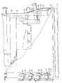
- FIG. 1 a form, fill, seal packaging machine 10 is illustrated.
- the web of film 12 is fed into the packaging machine 10 through an opening 14.
- the web of film 12 is fed around a plurality of rollers 15, 16, 17, 18, 19, 20, and 21.
- the web of film 12 is then fed to a former 24 that folds the web of film longitudinally so that longitudinal abutting edges of the film can be sealed together to create the fin seal 25 at the fin seal station 26.
- the folded web of film 12 is then passed around a fill tube structure 28 and side seals are created at the side seal station 30.
- fitments can be attached to the web of film 12 at a fitment attaching station.
- the term "fill tube structure" means not only the fill tube but also other structures coupled thereto such as, for example, fitment attaching apparatus.
- the apparatus for placing the web of film 12 under tension of the present invention is situated between the fill tube structure 28 and side seal station 30, the apparatus for placing the web of film 12 under tension of the present invention.
- the apparatus 32 for placing the web of film 12 under tension includes a tracking clamp 34 and tensioning bar 36.
- the tracking clamp 34 and tensioning bar 36 cooperate to place the web of film 12 in a taut condition after it passes around the fill tube structure 28 so that side seals can be created in the web of film across a surface that substantially does not include wrinkles and/or creases.
- the film tracking clamp 34 of the present invention is illustrated. As illustrated, the film tracking clamp 34 is located in juxtaposition to an end 37 of the fill tube structure 28.
- the film tracking clamp 34 includes a plurality of rollers 38, 39, 40, 41, 42, 43, 44, and 45 that receive a portion of the folded web of film 12. Specifically, the portion of the web of film 12 that is received between the rollers 38, 39, 40, 41, 42, 43, 44, and 45 is the portion of the web of film 12 that has been sealed to create the fin seal 25 at the fin seal station 26.
- rollers 38, 39, 40, 41, 42, 43, 44, and 45 are constructed so that they freely rotate about shafts 48, 49, 50, 51, 52, 53, 54, and 55, respectively.
- Shafts 48, 50, 52, and 54 are fixed and thereby remain stationary, while shafts 49, 51, 53, and 55 are movable to allow the rollers 39, 41, 43, and 45 to pivot about pivot members 56, 57, 58, and 59.
- this pivoting of the rollers 39, 41, 43, and 45 allows the tracking clamp 34 to be "opened” to allow the web of film 12 to be inserted between the rollers 38, 39, 40, 41, 42, 43, 44, and 45 and then allows the rollers to then be "closed” to trap the web of film between the rollers 38, 39, 40, 41, 42, 43, 44, and 45.
- the tracking clamp 34 includes a mounting plate 60 to which the shafts 48, 50, 52, and 54 of the rollers 38, 40, 42, and 44 are secured.
- the shafts 49, 51, 53, and 55 of the rollers 39, 41, 43, and 45 are secured to plate members 61, 62, 63, and 64 that are secured to arms 65, 66, 67, and 68, respectively, at pivot points 56, 57, 58, and 59.
- the pivot points 56, 57, 58, and 59 are secured to the mounting plate 60.
- the arms 65, 66, 67, and 68 are secured to an adjustment plate 69.
- the adjustment plate 69 is vertically moveable causing the plate members 61, 62, 63, and 64 and thereby the rollers 39, 41, 43, and 45, to pivot about the pivot points 56, 57, 58, and 59 opening or closing the tracking clamp 34.
- the tracking clamp 34 further includes a spring plate 70.
- the spring plate 70 is adjustably secured to the mounting plate 60 by screws 71 and 73 that are received within slots 75 and 77 in the spring plate 70 and corresponding apertures in the mounting plate 60.
- Each of the arms 65, 66, 67, and 68 is coupled to a flange 78, 79, 80, and 81 on the spring plate 70 by a spring 83, 85, 87, and 89.
- each arm 65, 66, 67, and 68 includes an aperture 91, 93, 95, and 97, respectively, for receiving a portion of the spring 83, 85, 87, and 89.
- the springs 83, 85, 87, and 89 urge the lever arms 65, 66, 67, and 68 downwardly causing the rollers 39, 41, 43, and 45 to be urged against rollers 38, 40, 42, and 44 thereby clamping the side 100 of the web of film 12 fed therebetween.
- a toggle switch 99 is provided in order to open the tracking clamp 34, i.e., to cause the rollers 39, 41, 43, and 45 not to be urged against rollers 38, 40, 42, and 44.
- the toggle switch 99 when moved clockwise causes the adjustment plate 69 to move upwardly causing the arms 65, 66, 67, and 68 to move upwardly forcing the plates 61, 62, 63, and 64, and thereby the rollers 39, 41, 43, and 45 to move downwardly away from the corresponding rollers 38, 40, 42, and 44, placing the tracking clamp 34 into an open position.
- the adjustment plate 69 is forced downward causing the rollers 39, 41, 43, and 45 to contact the corresponding rollers 38, 40, 42, and 44 trapping a side of the folded web of film 12 position between the rollers therebetween.
- the force with which the rollers 39, 41, 43, and 45 are urged against rollers 38, 40, 42, and 44 can be controlled by adjusting the position of the spring plate 70 with respect to the mounting plate 60. This can be done by adjusting the position of the screws 71 and 73 with respect to the slots 75 and 77 within which they are received or by a spring tensioning screw 121.
- the toggle switch 99 is moved to an open position causing the rollers 39, 41, 43, and 45 to move away from the corresponding rollers 38, 40, 42, and 44.
- the side 100 of the web of film 12 can then be fed therebetween and the toggle switch 99 moved to a closed position wherein rollers 39, 41, 43, and 45 are urged against the corresponding rollers 38, 40, 42, and 44.
- the tracking clamp 34 thereby functions to trap a first side 100 of the folded web of film 12 between the rollers 38, 39, 40, 41, 42, 43, 44, and 45.
- the side 100 of the folded web of film 12 received within the roller clamp 34 will include the abutting longitudinal edges of the web of film that are sealed to create the fin seal 25 in the film.
- rollers 38, 39, 40, 41, 42, 43, 44, and 45 freely rotate about their respective shafts 49, 51, 53, and 55, as the web of film 12 is pulled through the packaging machine 10, the film freely flows through the tracking clamp 34. Accordingly, the tracking clamp 34 does not unduly slow down the flow of the web of film 12 through the packaging machine 10.
- the tracking clamp 34 and specifically, the rollers 38, 39, 40, 41, 42, 43, 44, and 45 are not oriented so that they are exactly parallel to the side 100 of the folded web of film 12. Instead, the tracking clamp 34 and specifically, the rollers 38, 39, 40, 41, 42, 43, 44, and 45 are located at least one degree out of parallel to the side 100 of the folded web of film 12. Preferably, the rollers 38, 39, 40, 41, 42, 43, 44, and 45 are located approximately 2 to about 5 degrees out of parallel with the side 100 of the web of film 12.
- the tracking clamp 34 is illustrated as having four pairs of rollers 38, 39, 40, 41, 42, 43, 44, and 45, additional or fewer rollers can be utilized depending upon requirements.
- the rollers 38, 39, 40, 41, 42, 43, 44, and 45 are covered with a material having a sufficiently high coefficient of friction so that the rollers grip the folded web of film 12 but do not damage the film as it is pulled therethrough.
- the rollers 38, 39, 40, 41, 42, 43, 44, and 45 are covered with a high tear strength rubber.
- rollers 38, 39, 40, 41, 42, 43, 44, and 45 to have a minimum squeeze, and as a result reduces any drag on the folded web of film 12 as it is pulled through the form, fill, seal packaging machine 10 yet provides a maximum gripping force for the rollers.
- the tensioning bar 36 extends from a bottom 37 of the fill tube 28.
- the tensioning bar 36 includes a tensioning arm 103 that is pivotably connected by a pivot member 104 to a pivot arm 105.
- a collar shaft spring 107 located between the tensioning arm 103 and pivot arm 105, urges the tensioning arm 103 outwardly away from the pivot arm 105. As illustrated in Figure 2, this causes the tensioning arm 32 to urge a second side 108 of the folded web of film 12 outwardly.
- the collar shaft spring 107 includes at each end thereof pins 109 and 111 that are received within the tensioning arm 103 and pivot arm 105, respectively.
- a compression spring 113 is located between the tensioning arm 103 and pivot arm 105 and biases the tensioning arm 103 away from the pivot arm 105.
- the tensioning arm 103 preferably is sloped downwardly at a film contact side 115 thereof. This sloped portion of the tensioning arm 103 at the film contact side 115 reduces any drag on the web of film 12 as it is fed past the tensioning arm 36
- the tensioning bar 36 and film tracking clamp 34 cooperate to put the folded web of film 12 under tension and in a taut condition before it is sealed at the side seal station 30 As discussed above, this is accomplished by the rollers 38, 39, 40, 41, 42, 43, 44, and 45 pulling a side 100 of the folded web of film 12 outwardly in a first direction while the tensioning bar 36 urges an opposite side 108 of the folded web of film 12 in an opposite second direction. Accordingly, the web of film 12 is placed in tension between the tracking clamp 34 and the tension bar 36 and is therefore in a taut condition at the side sealing station 30.
Landscapes
- Engineering & Computer Science (AREA)
- Mechanical Engineering (AREA)
- Containers And Plastic Fillers For Packaging (AREA)
- Registering, Tensioning, Guiding Webs, And Rollers Therefor (AREA)
Claims (19)
- Vorrichtung zum Einlegen einer gefalteten gespannten Folienbahn in einer Versiegelstation (30) mit einer Versiegeleinrichtung als Teil einer Form-, Abfüll- und Einsiegel-Verpackungsmaschine, wobei die Maschine (10) eine Einrichtung aufweist, welche die Folie durch die Versiegelstation zieht, gekennzeichnet durch:
eine Vielzahl von Rollenpaaren (38, 39; 40, 41; 42, 43; 44, 55), die neben einem Ende einer Füllrohrkonstruktion (37) liegen und sich zu einer Stelle nahe der Versiegeleinrichtung erstreckt, wobei eine erste Seite der gefalteten Folienbahn (100) zwischen den Rollen hindurchgeführt wird und die Vielzahl von Rollen jeweils auf einer Welle (48, 49, 50, 51, 52, 53, 54, 55) so angebracht ist, daß die Rollen frei drehbar sind, wodurch die Folie durch die Versiegelstation (30) gezogen werden kann, während die Rollen um mindestens ein Grad gegenüber der Parallelen zur ersten Seite (100) der gefalteten Folienbahn versetzt angebracht sind und die erste Seite der gefalteten Folienbahn in einer ersten Richtung gezogen wird, während die Folie durch die Versiegelstation gezogen wird; und
eine Spannstange (36), die sich vom Ende der Füllrohrkonstruktion (37) aus erstreckt und eine zweite Seite der gefalteten Folienbahn (108) in einer zweiten, diametral der ersten entgegengesetzten Richtung spannt, wobei sich die Spannstange zu einer Stelle nahe der Versiegeleinrichtung (30) erstreckt, die im wesentlichen gleich der Stelle ist, zu welcher sich die Rollen hin erstrecken, wobei die Rollen und die Spannstange so aufgebaut und angeordnet sind, daß die Folie in der Versiegelstation straff gespannt ist. - Vorrichtung nach Anspruch 1, bei welcher die Rollen (38, 39, 40, 41, 42, 43, 44, 45) eine Kontaktfläche aus Gummi aufweisen.
- Vorrichtung nach Anspruch 1 oder 2, bei welcher jedes Rollenpaar eine erste Rolle (39, 41, 43, 45) und eine zweite Rolle (38, 40, 42, 44) aufweist; und die Rollen mit einer Einrichtung so gekoppelt sind, daß die erste Rolle zur Bewegung in eine erste Stellung veranlaßt wird, in welcher ein Abschnitt der gefalteten Folienbahn zwischen das Rollenpaar eingeschoben werden kann, und in welcher die erste Rolle zur Bewegung in eine zweite Stellung veranlaßt wird, in welcher der Abschnitt der gefalteten Folienbahn zwischen der ersten und der zweiten Rolle festgeklemmt wird.
- Vorrichtung nach Anspruch 3, bei welcher die erste Rolle mit einem federgespannten Arm (65, 66, 67, 68) gekoppelt ist, welcher die erste Rolle (39, 41, 43, 45) gegen die zweite Rolle (38, 40, 42, 44) spannt, wenn sich die erste Rolle in der zweiten Stellung befindet.
- Vorrichtung nach Anspruch 4, mit einer Einrichtung (71, 73; 75, 77) zum Einstellen des Drucks, mit welchem die erste Rolle gegen die zweite Rolle gespannt wird.
- Vorrichtung nach Anspruch 5, bei welcher die Einrichtung zum Einstellen des Drucks eine Einrichtung zum Einstellen des Drucks aufweist, mit welchem die Feder den Arm spannt.
- Vorrichtung nach jedem vorhergehenden Anspruch, welche vier Rollenpaare (38, 39; 40, 41; 42, 43; 44, 45) aufweist.
- Vorrichtung nach jedem vorhergehenden Anspruch, bei welcher die Rollen um etwa 2 bis 5 Grad gegenüber der Parallelen versetzt angeordnet sind.
- Vorrichtung nach jedem vorhergehenden Anspruch, bei welcher die Spannstange (30) einen Spannarm (103) aufweist, der federgespannt ist.
- Vorrichtung nach Anspruch 9, bei welcher der Spannarm (103) durch eine Ringfeder (107) federgespannt ist.
- Vorrichtung nach Anspruch 3, 4, 5, oder 6, mit einem Kipphebelschalter (99), der so mit dem Arm gekoppelt ist, daß er diesen zur Bewegung der ersten Rolle in die erste oder zweite Stellung veranlaßt.
- Vorrichtung nach Anspruch 4, 5, 6 oder 11, bei welcher die Feder (83, 85, 82, 89) an einem Ende am Arm (65, 66, 67, 68) und an einem zweiten Ende an einer verstellbaren Platte (70) mit einer Einrichtung zur Einstellung der Stellung der Platte gegenüber dem Arm befestigt ist.
- Vorrichtung nach Anspruch 1, bei welcher die Spannstange (36) in die zweite Richtung federgespannt ist.
- Form-, Abfüll- und Einsiegel-Verpackungsmaschine (10) zur Bildung elastischer Beutel zur Aufnahme eines Materials aus einer elastischen Folienbahn (32), welche folgendes aufweist:
ein Einfüllrohr (28), wobei die Verpackungsmaschine eine Einrichtung (24) aufweist, welche die Folie um das Einfüllrohr führt, und wobei das Einfüllrohr an einem Ende eine Einrichtung zum Ablegen eines Produkts in der Folienbahn aufweist;
eine Versiegeleinrichtung (26) zur Bildung von Seitennähten (25) in der Folienbahn, wobei die Versiegeleinrichtung unterhalb eines Endes des Einfüllrohrs angeordnet ist; und
eine Vorrichtung, welche eine gefaltete Folienbahn in gespanntem Zustand in einer Versiegelstation (30) gemäß jedem vorhergehenden Anspruch einlegt. - Verfahren zum Einlegen einer gefalteten gespannten Folienbahn in einer Verpackungsmaschine, welches die folgenden Schritte aufweist:
Führen der Folienbahn (12) über ein Formteil (24), welches die Folienbahn faltet;
Führen der gefalteten Folienbahn um eine Füllrohrkonstruktion (28);
dadurch gekennzeichnet, daß eine erste Seite der gefalteten Folienbahn durch eine Vielzahl von Rollenpaaren (38, 39; 40, 41; 42, 43; 44, 45) geführt wird, welche nicht parallel zur ersten Seite der Folienbahn angeordnet sind;
daß die erste Seite der Folienbahn (110) durch die Rollen in eine erste Richtung gezogen wird;
daß eine Spanneinrichtung eine Bewegung einer zweiten Seite der Folienbahn (108) in die erste Richtung verhindert; und
daß in einer ersten und zweiten Richtung weiterhin eine Zugkraft auch nach Bewegung der Folienbahn (12) in eine Stellung unterhalb eines untersten Abschnitts der Füllrohrkonstruktion ausgeübt wird. - Verfahren nach Anspruch 15, welches den Arbeitsschritt aufweist, daß die zweite Seite der gefalteten Folienbahn (108) in eine der ersten entgegengesetzte zweite Richtung gespannt wird.
- Verfahren nach Anspruch 15 oder 16, welches den Arbeitsschritt aufweist, daß auf einer ersten Seite der Folienbahn vor dem Durchtritt der gefalteten Folienbahn durch die Rollenpaare (38, 39; 40, 42; 42, 43; 44, 45) eine wulstförmige Siegelnaht (25) gebildet wird.
- Verfahren zur Bildung einer elastischen Verpackung aus einer Folienbahn in einer Form-, Abfüll- und Einsiegel-Verpackungsmaschine, welches das Verfahren nach den Anspruch 15 oder 16 und die weiteren Schritte umfaßt:
Bilden einer wulstförmigen Siegelnaht (25) auf einer ersten Seite (100) der gefalteten Folienbahn;
Durchführen der ersten Seite (100) der Folienbahn durch eine Vielzahl von Rollenpaaren (38, 39; 40, 41; 42, 43; 44, 45);
Veranlassen der Vielzahl von Rollenpaaren, die erste Seite der Folie in eine erste Richtung zu ziehen;
Spannen einer zweiten Seite (108) der gefalteten Folienbahn in eine zweite Richtung mit Hilfe einer Spanneinrichtung (36);
Veranlassen eines weiteren Spannens der gefalteten Folienbahn in die erste und zweite Richtung durch die Rollen und die Spanneinrichtung auch nach Bewegung der Folie in eine Stellung unterhalb des untersten Abschnitts der Füllrohrkonstruktion; und
Abschließen einer Länge der Rollen und der Spanneinrichtung an einer Position neben einer Versiegeleinrichtung, wobei die Folie zwischen einem Ende des Einfüllrohrs und der Versiegeleinrichtung gespannt wird. - Verfahren nach Anspruch 18, welches den Arbeitsschritt der Bildung von Seitennahten mit der Versiegeleinrichtung (30) in der gefalteten Folienbahn (12) aufweist, während die Folienbahn straff gespannt ist.
Applications Claiming Priority (2)
| Application Number | Priority Date | Filing Date | Title |
|---|---|---|---|
| US77707 | 1987-07-24 | ||
| US07/077,707 US4829746A (en) | 1987-07-24 | 1987-07-24 | Apparatus for placing a web of film under tension |
Publications (3)
| Publication Number | Publication Date |
|---|---|
| EP0300780A2 EP0300780A2 (de) | 1989-01-25 |
| EP0300780A3 EP0300780A3 (en) | 1989-11-15 |
| EP0300780B1 true EP0300780B1 (de) | 1993-03-03 |
Family
ID=22139615
Family Applications (1)
| Application Number | Title | Priority Date | Filing Date |
|---|---|---|---|
| EP88306689A Expired - Lifetime EP0300780B1 (de) | 1987-07-24 | 1988-07-21 | Apparat zum Setzen eines Filmbands unter Spannung |
Country Status (5)
| Country | Link |
|---|---|
| US (1) | US4829746A (de) |
| EP (1) | EP0300780B1 (de) |
| JP (1) | JP2657523B2 (de) |
| CA (1) | CA1328805C (de) |
| DE (1) | DE3878768T2 (de) |
Families Citing this family (17)
| Publication number | Priority date | Publication date | Assignee | Title |
|---|---|---|---|---|
| US4947621A (en) * | 1988-11-18 | 1990-08-14 | Triparte, Ltd. | Vertical form/fill/seal machine for making three side fin pouches |
| US4974395A (en) * | 1990-01-22 | 1990-12-04 | Zip-Pak Incorporated | Zipper guide and spreader device for form, fill and seal machines |
| US5014497A (en) * | 1990-03-06 | 1991-05-14 | Zip-Pak, Incorporated | Method and apparatus for smoothing of bag making material in form, fill and seal machines |
| GB9111635D0 (en) * | 1991-05-30 | 1991-07-24 | Datum Appropriate Techn Ltd | Packaging machine |
| US5400565A (en) * | 1992-06-29 | 1995-03-28 | Pacmac, Inc. | Vertical form, fill and seal packaging machine for making recloseable product filled bags |
| US5930983A (en) * | 1992-06-29 | 1999-08-03 | Pacmac, Inc. | Form, fill and seal packaging machine with bag squeezer and method |
| US5768852A (en) * | 1992-06-29 | 1998-06-23 | Pacmac, Inc. | Vertical form, fill and seal machine, components and method for making reclosable bags |
| US5505037A (en) * | 1992-06-29 | 1996-04-09 | Pacmac, Inc. | Vertical form, fill and seal machine for making recloseable bags |
| US6553744B1 (en) | 1992-06-29 | 2003-04-29 | Pacmac, Inc. | Packaging machine |
| US5746043A (en) * | 1992-06-29 | 1998-05-05 | Pacmac, Inc. | Convertible form, fill and seal packaging machine and method |
| JPH0721501U (ja) * | 1993-04-27 | 1995-04-18 | 雪印食品株式会社 | 縦シール部しわ取り装置 |
| JP3687924B2 (ja) * | 1995-05-24 | 2005-08-24 | 株式会社イシダ | 縦型ピロー包装機 |
| US6539692B1 (en) | 1998-12-18 | 2003-04-01 | Siptop Packaging, Inc. | Form, fill and seal container forming apparatus |
| EP1205294A3 (de) * | 2000-11-13 | 2003-05-21 | Arkmount Systems Inc. | Mechanismus zum Schweissen und Schneiden und Vorrichtung zur Verformung eines Behälters mit diesem |
| US6668526B2 (en) | 2001-04-27 | 2003-12-30 | Baxter International, Inc. | Web centering system |
| CN101407255B (zh) * | 2008-07-03 | 2011-02-16 | 上海伟隆包装设备有限公司 | 卷状包装袋放料装置 |
| CN110371375B (zh) * | 2019-07-25 | 2021-03-02 | 海宁南化环保科技有限公司 | 一种干燥剂自动包装机 |
Family Cites Families (23)
| Publication number | Priority date | Publication date | Assignee | Title |
|---|---|---|---|---|
| US3149447A (en) * | 1961-12-08 | 1964-09-22 | Mayer & Co Inc O | Tube feeding mechanism for packaging machine |
| DE1186392B (de) * | 1962-12-01 | 1965-01-28 | Otto Rist | Maschine zum Herstellen gefuellter und verschlossener Beutel mit rechteckigem, standfestem Boden |
| BE645834A (de) * | 1963-03-27 | |||
| FR1380593A (fr) * | 1963-10-11 | 1964-12-04 | Etude & D Applic Ind Df Brevet | Dispositif d'entraînement et de guidage d'une feuille souple continue |
| SE331448B (de) * | 1966-06-30 | 1970-12-21 | Tetra Pak Ab | |
| US3613524A (en) * | 1970-02-24 | 1971-10-19 | Dow Chemical Co | Method and apparatus for manufacturing bag stock |
| US3681892A (en) * | 1970-08-26 | 1972-08-08 | Hayssen Mfg Co | Packaging machine |
| DE2137454A1 (de) * | 1971-07-27 | 1973-02-08 | Erhardt & Leimer Kg | Vorrichtung zum geradefuehren von warenbahnen |
| US3975888A (en) * | 1972-04-26 | 1976-08-24 | R. A. Jones & Company, Inc. | Method and apparatus for forming, filling and sealing packages |
| US3752377A (en) * | 1972-09-01 | 1973-08-14 | Mount Hope Machinery Ltd | Method and apparatus for controlling lateral spacings of elongated elements |
| JPS5324850Y2 (de) * | 1973-07-13 | 1978-06-26 | ||
| FR2240866B1 (de) * | 1973-08-14 | 1978-05-19 | Prepac Sarl | |
| US4007865A (en) * | 1974-10-04 | 1977-02-15 | Cape Colony Manufacturing, Inc. | Web guiding and centering apparatus |
| US4004399A (en) * | 1975-03-13 | 1977-01-25 | Foodways National, Inc. | Packaging machine |
| JPS5521923Y2 (de) * | 1976-08-26 | 1980-05-26 | ||
| US4043098A (en) * | 1976-08-26 | 1977-08-23 | Package Machinery Company | Vertical form, fill and seal packaging machine with improved back-up bar for longitudinal sealing |
| US4117647A (en) * | 1976-10-20 | 1978-10-03 | Rossi Alfred F | Flexible pouch, forming, filling and sealing machine |
| US4103473A (en) * | 1977-08-24 | 1978-08-01 | Atlas Powder Company | Apparatus for making a compartmented container |
| US4235362A (en) * | 1979-03-21 | 1980-11-25 | Pfizer Inc. | Wire-feeding apparatus |
| GB2065599B (en) * | 1979-12-20 | 1983-12-07 | Rowell F J | Liquid packaging system |
| US4534159A (en) * | 1982-11-12 | 1985-08-13 | General Packaging Equipment Company | Apparatus for forming, filling and sealing bags with fluid contents |
| JPS60154206U (ja) * | 1984-03-27 | 1985-10-15 | オリヒロ株式会社 | 横シ−ルしわ防止装置 |
| JPS6216323A (ja) * | 1985-07-05 | 1987-01-24 | 株式会社川島製作所 | 製袋充填包装機の縦シ−ラ−送り装置 |
-
1987
- 1987-07-24 US US07/077,707 patent/US4829746A/en not_active Expired - Lifetime
-
1988
- 1988-07-14 CA CA000572046A patent/CA1328805C/en not_active Expired - Lifetime
- 1988-07-21 DE DE8888306689T patent/DE3878768T2/de not_active Expired - Lifetime
- 1988-07-21 EP EP88306689A patent/EP0300780B1/de not_active Expired - Lifetime
- 1988-07-21 JP JP63182777A patent/JP2657523B2/ja not_active Expired - Lifetime
Also Published As
| Publication number | Publication date |
|---|---|
| US4829746A (en) | 1989-05-16 |
| EP0300780A2 (de) | 1989-01-25 |
| DE3878768D1 (de) | 1993-04-08 |
| JP2657523B2 (ja) | 1997-09-24 |
| DE3878768T2 (de) | 1993-06-09 |
| CA1328805C (en) | 1994-04-26 |
| EP0300780A3 (en) | 1989-11-15 |
| JPS6448762A (en) | 1989-02-23 |
Similar Documents
| Publication | Publication Date | Title |
|---|---|---|
| EP0300780B1 (de) | Apparat zum Setzen eines Filmbands unter Spannung | |
| US4969310A (en) | Packaging machine and method | |
| US4829745A (en) | Tube spreader for removing wrinkles in tube stock | |
| EP1008523B1 (de) | Verpackungsverfahren für ein Band von zusammenhängenden Beuteln | |
| CA1222233A (en) | Continuous flow weldable package former filler seamer and cleaver | |
| US3738080A (en) | Packing machine | |
| US6890290B2 (en) | Method and apparatus for producing valve bags | |
| US3492775A (en) | Bagging | |
| US4697403A (en) | Bag spreaders | |
| EP0602000A1 (de) | Verbesserungen an vertikalen Form- und Füllmaschinen | |
| US4768330A (en) | Bag gripper and spreader for form, fill and seal bagging machine | |
| US3952480A (en) | Packaging apparatus | |
| US3938299A (en) | Packaging system and method | |
| US4590747A (en) | Positive displacement filling machine | |
| IE48821B1 (en) | Method and apparatus for packaging commodities | |
| US5282351A (en) | Method for making, filling and sealing sacks | |
| US5271206A (en) | Method for making, filling, and sealing sacks | |
| JP2842180B2 (ja) | 包装装置 | |
| US3575763A (en) | Method and apparatus for fabricating high impact strength,contoured-bottom bags | |
| US4289567A (en) | Apparatus for applying web sections to a flat-lying workpiece | |
| WO2004041660A2 (en) | Method and apparatus for producing valve bags | |
| US12157598B2 (en) | Vertical-flow wrapper and method to produce a bag | |
| JPH0223522Y2 (de) | ||
| JP4164766B2 (ja) | 袋詰品シール方法 | |
| AU642908B2 (en) | Packaging machine and method |
Legal Events
| Date | Code | Title | Description |
|---|---|---|---|
| PUAI | Public reference made under article 153(3) epc to a published international application that has entered the european phase |
Free format text: ORIGINAL CODE: 0009012 |
|
| AK | Designated contracting states |
Kind code of ref document: A2 Designated state(s): DE FR GB SE |
|
| PUAL | Search report despatched |
Free format text: ORIGINAL CODE: 0009013 |
|
| AK | Designated contracting states |
Kind code of ref document: A3 Designated state(s): DE FR GB SE |
|
| 17P | Request for examination filed |
Effective date: 19900330 |
|
| 17Q | First examination report despatched |
Effective date: 19920210 |
|
| GRAA | (expected) grant |
Free format text: ORIGINAL CODE: 0009210 |
|
| AK | Designated contracting states |
Kind code of ref document: B1 Designated state(s): DE FR GB SE |
|
| REF | Corresponds to: |
Ref document number: 3878768 Country of ref document: DE Date of ref document: 19930408 |
|
| ET | Fr: translation filed | ||
| PLBE | No opposition filed within time limit |
Free format text: ORIGINAL CODE: 0009261 |
|
| STAA | Information on the status of an ep patent application or granted ep patent |
Free format text: STATUS: NO OPPOSITION FILED WITHIN TIME LIMIT |
|
| 26N | No opposition filed | ||
| EAL | Se: european patent in force in sweden |
Ref document number: 88306689.6 |
|
| REG | Reference to a national code |
Ref country code: GB Ref legal event code: IF02 |
|
| PGFP | Annual fee paid to national office [announced via postgrant information from national office to epo] |
Ref country code: DE Payment date: 20070831 Year of fee payment: 20 |
|
| PGFP | Annual fee paid to national office [announced via postgrant information from national office to epo] |
Ref country code: GB Payment date: 20070727 Year of fee payment: 20 |
|
| PGFP | Annual fee paid to national office [announced via postgrant information from national office to epo] |
Ref country code: SE Payment date: 20070727 Year of fee payment: 20 |
|
| PGFP | Annual fee paid to national office [announced via postgrant information from national office to epo] |
Ref country code: FR Payment date: 20070717 Year of fee payment: 20 |
|
| REG | Reference to a national code |
Ref country code: GB Ref legal event code: PE20 Expiry date: 20080720 |
|
| EUG | Se: european patent has lapsed | ||
| PG25 | Lapsed in a contracting state [announced via postgrant information from national office to epo] |
Ref country code: GB Free format text: LAPSE BECAUSE OF EXPIRATION OF PROTECTION Effective date: 20080720 |