EP0300902A1 - Handgesteuerte Sprühanlage und Druckluftsprühpistole für ein Beschichtungsprodukt - Google Patents
Handgesteuerte Sprühanlage und Druckluftsprühpistole für ein Beschichtungsprodukt Download PDFInfo
- Publication number
- EP0300902A1 EP0300902A1 EP88401881A EP88401881A EP0300902A1 EP 0300902 A1 EP0300902 A1 EP 0300902A1 EP 88401881 A EP88401881 A EP 88401881A EP 88401881 A EP88401881 A EP 88401881A EP 0300902 A1 EP0300902 A1 EP 0300902A1
- Authority
- EP
- European Patent Office
- Prior art keywords
- trigger
- components
- installation according
- coating product
- air flow
- Prior art date
- Legal status (The legal status is an assumption and is not a legal conclusion. Google has not performed a legal analysis and makes no representation as to the accuracy of the status listed.)
- Granted
Links
- 238000009434 installation Methods 0.000 title claims abstract description 26
- 239000011248 coating agent Substances 0.000 title claims abstract description 16
- 238000000576 coating method Methods 0.000 title claims abstract description 16
- 238000005507 spraying Methods 0.000 title claims abstract description 13
- 239000007921 spray Substances 0.000 title claims abstract description 10
- 230000000750 progressive effect Effects 0.000 claims abstract description 6
- 238000011144 upstream manufacturing Methods 0.000 claims description 5
- 239000000835 fiber Substances 0.000 claims 1
- 239000003973 paint Substances 0.000 abstract description 34
- 239000004848 polyfunctional curative Substances 0.000 description 5
- 238000010586 diagram Methods 0.000 description 2
- 239000000203 mixture Substances 0.000 description 2
- 238000010926 purge Methods 0.000 description 2
- 238000005096 rolling process Methods 0.000 description 2
- 239000002904 solvent Substances 0.000 description 2
- 238000004140 cleaning Methods 0.000 description 1
- 239000003086 colorant Substances 0.000 description 1
- 230000007547 defect Effects 0.000 description 1
- 230000001627 detrimental effect Effects 0.000 description 1
- 238000001035 drying Methods 0.000 description 1
- 230000001939 inductive effect Effects 0.000 description 1
- 239000007788 liquid Substances 0.000 description 1
- 230000007257 malfunction Effects 0.000 description 1
- 239000000463 material Substances 0.000 description 1
- 239000013307 optical fiber Substances 0.000 description 1
- 239000002966 varnish Substances 0.000 description 1
Images

Classifications
-
- B—PERFORMING OPERATIONS; TRANSPORTING
- B05—SPRAYING OR ATOMISING IN GENERAL; APPLYING FLUENT MATERIALS TO SURFACES, IN GENERAL
- B05B—SPRAYING APPARATUS; ATOMISING APPARATUS; NOZZLES
- B05B12/00—Arrangements for controlling delivery; Arrangements for controlling the spray area
- B05B12/14—Arrangements for controlling delivery; Arrangements for controlling the spray area for supplying a selected one of a plurality of liquids or other fluent materials or several in selected proportions to a spray apparatus, e.g. to a single spray outlet
- B05B12/1418—Arrangements for controlling delivery; Arrangements for controlling the spray area for supplying a selected one of a plurality of liquids or other fluent materials or several in selected proportions to a spray apparatus, e.g. to a single spray outlet for supplying several liquids or other fluent materials in selected proportions to a single spray outlet
-
- B—PERFORMING OPERATIONS; TRANSPORTING
- B05—SPRAYING OR ATOMISING IN GENERAL; APPLYING FLUENT MATERIALS TO SURFACES, IN GENERAL
- B05B—SPRAYING APPARATUS; ATOMISING APPARATUS; NOZZLES
- B05B12/00—Arrangements for controlling delivery; Arrangements for controlling the spray area
- B05B12/002—Manually-actuated controlling means, e.g. push buttons, levers or triggers
-
- B—PERFORMING OPERATIONS; TRANSPORTING
- B05—SPRAYING OR ATOMISING IN GENERAL; APPLYING FLUENT MATERIALS TO SURFACES, IN GENERAL
- B05B—SPRAYING APPARATUS; ATOMISING APPARATUS; NOZZLES
- B05B12/00—Arrangements for controlling delivery; Arrangements for controlling the spray area
- B05B12/08—Arrangements for controlling delivery; Arrangements for controlling the spray area responsive to condition of liquid or other fluent material to be discharged, of ambient medium or of target ; responsive to condition of spray devices or of supply means, e.g. pipes, pumps or their drive means
-
- B—PERFORMING OPERATIONS; TRANSPORTING
- B05—SPRAYING OR ATOMISING IN GENERAL; APPLYING FLUENT MATERIALS TO SURFACES, IN GENERAL
- B05B—SPRAYING APPARATUS; ATOMISING APPARATUS; NOZZLES
- B05B7/00—Spraying apparatus for discharge of liquids or other fluent materials from two or more sources, e.g. of liquid and air, of powder and gas
- B05B7/02—Spray pistols; Apparatus for discharge
- B05B7/12—Spray pistols; Apparatus for discharge designed to control volume of flow, e.g. with adjustable passages
- B05B7/1254—Spray pistols; Apparatus for discharge designed to control volume of flow, e.g. with adjustable passages the controlling means being fluid actuated
- B05B7/1263—Spray pistols; Apparatus for discharge designed to control volume of flow, e.g. with adjustable passages the controlling means being fluid actuated pneumatically actuated
- B05B7/1272—Spray pistols; Apparatus for discharge designed to control volume of flow, e.g. with adjustable passages the controlling means being fluid actuated pneumatically actuated actuated by gas involved in spraying, i.e. exiting the nozzle, e.g. as a spraying or jet shaping gas
- B05B7/1281—Serial arrangement, i.e. a single gas stream acting on the controlling means first and flowing downstream thereof to the nozzle
-
- B—PERFORMING OPERATIONS; TRANSPORTING
- B05—SPRAYING OR ATOMISING IN GENERAL; APPLYING FLUENT MATERIALS TO SURFACES, IN GENERAL
- B05B—SPRAYING APPARATUS; ATOMISING APPARATUS; NOZZLES
- B05B7/00—Spraying apparatus for discharge of liquids or other fluent materials from two or more sources, e.g. of liquid and air, of powder and gas
- B05B7/24—Spraying apparatus for discharge of liquids or other fluent materials from two or more sources, e.g. of liquid and air, of powder and gas with means, e.g. a container, for supplying liquid or other fluent material to a discharge device
- B05B7/26—Apparatus in which liquids or other fluent materials from different sources are brought together before entering the discharge device
- B05B7/28—Apparatus in which liquids or other fluent materials from different sources are brought together before entering the discharge device in which one liquid or other fluent material is fed or drawn through an orifice into a stream of a carrying fluid
- B05B7/32—Apparatus in which liquids or other fluent materials from different sources are brought together before entering the discharge device in which one liquid or other fluent material is fed or drawn through an orifice into a stream of a carrying fluid the fed liquid or other fluent material being under pressure
Definitions
- the invention relates to an installation for spraying coating product with manual control, that is to say using a pneumatic sprayer with manual control, provided with an actuating trigger controlling both the flow of coating product (paint) and the opening of the valve controlling the supply of spray air for this product.
- the invention relates more particularly to improvements allowing better control of the air flows and of coating product. It finds a preferred application in installations using two-component paints or varnishes (typically a base and a hardener) in order to better control, in all circumstances, the volumetric ratio between these two components.
- two-component paints or varnishes typically a base and a hardener
- a conventional manual spray paint installation comprises at least one pneumatic sprayer provided with an actuating trigger and connected, on the one hand, to a paint supply duct and, on the other hand, to a duct compressed air supply.
- the paint is atomized and propelled by air towards the object to be painted.
- the user controls the spray of sprayed paint by pressing the trigger more or less.
- the paint passes through a valve controlled by the trigger.
- the actuation of this valve is proportional, that is to say that its arrangement is such that the flow rate of the valve is a function of the degree of depression of the trigger.
- the air inlet control valve also controlled by the trigger, is of the "all or nothing" type, that is to say that the air flow remains practically constant whatever the flow paint.
- the invention therefore essentially relates to a coating product spraying installation comprising at least one pneumatic sprayer with manual control, provided with an actuating trigger, connected to means for supplying product to be sprayed and to a source of compressed air, characterized in that said headlight comprises a means for progressive adjustment of the air flow rate, sensitive to the position of said actuating trigger.
- the invention relates to another improvement making it possible to control the paint flow more precisely, by means of a gear pump inserted in the paint supply circuit.
- the invention therefore also relates to an installation according to the above definition, characterized in that said means for supplying coating product comprise a gear pump driven by a variable speed motor, controlled by sensitive control means. , in particular, to an electrical signal representative of the position of said trigger.
- the installation in question will include a sensor for the spraying air flow rate and this sensor will be part of the means for generating the electrical signal representative of the position of the trigger.
- the invention therefore also relates to an installation in accordance with the preceding description and comprising a mixer of said components, inserted upstream of the projector and comprising two inputs, respectively for the two components and an output connected to said projector, characterized in that that gear pumps are respectively inserted in respective supply circuits of said components, upstream of said mixer and in that these pumps are respectively driven by variable speed motors, controlled by control means able to maintain the flow rates of said components in a predetermined ratio.
- a manually operated paint sprayer 10 conventionally comprising, a spray nozzle 11, a connection nozzle 12 connected to a paint supply conduit 12 a and a nozzle connection 14 connected to a compressed air supply duct 14 a .
- An actuating trigger 16 is articulated at 17 to the body of the projector. It is coupled to the needle of a proportional action valve (not shown) controlling the paint flow and, according to a an important characteristic of the invention, it is also coupled, by an articulated rod 19, to a means of progressive adjustment of the air flow.
- a flow control valve 21 comprising a shutter element 22 movable relative to a seat 23 defined in a chamber 24 between an inlet 25 connected to the nozzle 14 and a outlet 26 connected to the spraying means.
- the rod 19 is attached to the closure element 22 while a spring 28, located in the chamber 24, biases said closure element towards the seat 23, that is to say towards the closed position of valve.
- the progressive adjustment of the air flow, sensitive to the position of the trigger, is obtained by rolling the air over a certain variable axial distance, in an annular passage 30 defined between the closure element and the seat.
- the closure element comprises a substantially cylindrical core 22 a and the seat 23 comprises or is extended by a portion of conduit 23 a substantially cylindrical and of diameter greater than that of the core 22 a .
- the annular passage 30, of variable length, is defined between said core 22 a and said portion of conduit 23 a .
- This core, under the action of the rod 19 and the spring 28 is axially movable inside said portion of conduit.
- the length d thereof corresponds substantially to the stroke of the trigger.
- the pressure drop caused by the rolling of the air in the passage 30 and, consequently, the flow of atomizing air depend on the position of the trigger.
- the air flow and the paint flow vary with the position of said trigger.
- there will be a low air consumption avoiding drying the paint by an excess of air.
- FIG. 2 illustrates, in its simplest form, a coating product spraying installation using the projector of FIG. 1.
- the air supply means connected to the nozzle 14, comprise an air flow sensor 34 for measuring the spraying air flow rate determined by the valve 21.
- this sensor of any known type, is inserted between a source of compressed air, represented here by the conduit 36 and the projector 10. The sensor could of course be integrated into said projector.
- This sensor delivers at its output 34 to an electrical signal representative of the air flow and thus consequently the depression of the trigger.
- the coating material supply means comprise a gear pump 38 driven by a variable speed motor 39.
- This pump is here inserted between a paint circulation duct 40 and the nozzle 12.
- the motor 39 is supplied by control means 42 (for example a current amplifier) sensitive, in particular to an electrical signal representative of the position of the trigger 16. In the example described, this signal is precisely delivered by the electrical output 34 a of the sensor air flow 34.
- opto-electric means are used to develop the signal representative of the position of the trigger 16.
- the latter is mechanically linked to a reflecting element 44 pivotally mounted and this reflecting element is inserted into a circuit of optical fibers 45, 46 established between a light source 47 and an optoelectric sensor 48.
- the latter is part of the means for developing the electrical signal representative of the position of the trigger.
- the electrical signal output of the sensor 48 can be connected to the control means 42 in the same way as the output 34 a of the air flow sensor 34.
- FIG. 2 is preferable because it has the additional advantage of making the pump also sensitive to possible fluctuations in the air pressure.
- the paint flow rate can thus be automatically modified to maintain a substantially constant air-paint dosage. This avoids any excess paint and therefore, any risk of leakage.
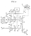
- FIG. 4 illustrates a particularly advantageous application of the invention, for the implementation of a two-component coating product, in particular a paint formed by the mixture of a colored base and a hardener.
- a mixer 50 inserted upstream from the projector 10.
- This mixer has two inputs 50 a , 50 b , for each of the two components at an output 51 connected to the connection end piece 12.
- the mixer is also connected, by a non-return valve 52, to a cleaning block 53, known per se, comprising an inlet for solvent 53 a and an inlet for compressed air 53 b .
- a paint supply circuit (or base) 55 and a hardener supply circuit 56 there is a paint supply circuit (or base) 55 and a hardener supply circuit 56.
- the output of circuit 55 is connected to input 50 a of the mixer, and the output of circuit 56 is connected to input 50 b of the mixer.
- the circuit 55 is connected to a color changing block 60, known per se, itself connected to several paint supply pipes or bases of different colors 61-63, to an air supply pipe 65 and to a solvent supply pipe 66.
- the circuit 55 thus successively comprises, between the color changing block 60 and the mixer, a gear pump 67 a driven by a variable speed electric motor 68 a , a flow sensor 69 a and a purge valve 70 a .
- a safety valve 71a is connected in parallel to the pump.
- the flow sensor 69 a is here advantageously of the "gear" type, that is to say that its mechanical part is very structurally similar to a gear pump.
- One of the pinions of this gear sensor is coupled to an inductive transducer 72 a whose electrical output delivers a signal representative of the flow of liquid in the circuit 55.
- the hardener circulation circuit 56 is quite comparable to the circuit 55 It is connected to a hardener circulation duct 78 and comprises, interconnected in the same way, a gear pump 67 b , driven by a motor 68 b , a flow sensor 69 b with its transducer 72 b , a valve safety 71 b and a purge valve 70 b .
- the compressed air supply means are similar to those of FIG. 2 and therefore comprise an air flow sensor 73 connected between the conduit 65 and the connection end piece 14.
- a computer 75 receives the output signals from the flow sensors 69 a and 69 b and from the air flow sensor 73 (delivering a signal representative of the position of the trigger) and delivers signals control with two current amplifiers 76 a , 76 b respectively supplying the motors 68 a , 68 b .
- the computer 75 is part of the engine control means 68 a , 68 b . It is programmed to maintain the flow rates of the two components flowing in the circuits 55 and 56, in a predetermined ratio.
- the system When the trigger is pulled very lightly, the system is set so that a low flow of spray air occurs before paint is admitted to the projector.
- the paint inlet valve control needle is then still closed.
- the pump is only allowed to operate from a certain level of air flow for which it is certain that the valve needle is actually open. All of these operating details can easily be taken into account by the computer 75.
- a minimum flow threshold is fixed below which the pump is stopped. The thresholds can be different on opening and closing. We can also anticipate the pump stopping before closing the needle, if the air flow sensor has a relatively slow response.
Landscapes
- Nozzles (AREA)
Applications Claiming Priority (2)
| Application Number | Priority Date | Filing Date | Title |
|---|---|---|---|
| FR8710213 | 1987-07-20 | ||
| FR8710213A FR2618354B1 (fr) | 1987-07-20 | 1987-07-20 | Installation de pulverisation de produit de revetement a commande manuelle et projecteur pneumatique d'un tel produit de revetement |
Publications (2)
| Publication Number | Publication Date |
|---|---|
| EP0300902A1 true EP0300902A1 (de) | 1989-01-25 |
| EP0300902B1 EP0300902B1 (de) | 1991-04-24 |
Family
ID=9353310
Family Applications (1)
| Application Number | Title | Priority Date | Filing Date |
|---|---|---|---|
| EP88401881A Expired - Lifetime EP0300902B1 (de) | 1987-07-20 | 1988-07-20 | Handgesteuerte Sprühanlage und Druckluftsprühpistole für ein Beschichtungsprodukt |
Country Status (4)
| Country | Link |
|---|---|
| US (1) | US4998672A (de) |
| EP (1) | EP0300902B1 (de) |
| DE (2) | DE3862541D1 (de) |
| FR (1) | FR2618354B1 (de) |
Cited By (4)
| Publication number | Priority date | Publication date | Assignee | Title |
|---|---|---|---|---|
| EP0420181A3 (en) * | 1989-09-27 | 1992-04-22 | Union Carbide Chemicals And Plastics Company, Inc. | Method and apparatus for metering and mixing noncompressible and compressible fluids |
| EP0605138A1 (de) * | 1992-12-30 | 1994-07-06 | Nordson Corporation | Abgabesystem für Beschichtungsmaterial, welches einen Katalysator enthält |
| EP0605137A1 (de) * | 1992-12-30 | 1994-07-06 | Nordson Corporation | Verfahren und Vorrichtung zur Herstellung und Abgabe eines Mehrkomponenten-Beschichtungsmaterials |
| RU2277443C2 (ru) * | 2000-11-29 | 2006-06-10 | Акцо Нобель Н.В. | Способ различного нанесения составов покрытий с использованием многокомпонентного аппарата, содержащего три или большее число компонентов |
Families Citing this family (29)
| Publication number | Priority date | Publication date | Assignee | Title |
|---|---|---|---|---|
| CA2107523C (en) * | 1993-10-01 | 2004-05-04 | Gary D. Langeman | Plural component delivery system |
| US5478014A (en) * | 1994-04-20 | 1995-12-26 | Hynds; James E. | Method and system for hot air spray coating and atomizing device for use therein |
| US5836031A (en) * | 1996-06-07 | 1998-11-17 | Minnesota Mining And Manufacturing Company | Fiber optic cable cleaner |
| WO1998041316A1 (en) | 1997-03-19 | 1998-09-24 | Akzo Nobel N.V. | Apparatus for applying multi-component coating compositions |
| US6010032A (en) * | 1997-06-19 | 2000-01-04 | Emes N.V. | Continuous dispensing system for liquids |
| EP0885659A1 (de) * | 1997-06-19 | 1998-12-23 | Emes N.V. | System zur kontinuierlichen Abgabe von Flüsssigkeiten |
| FR2794384B1 (fr) * | 1999-06-04 | 2001-10-05 | Sames Sa | Procede d'alimentation de produits de revetement pour l'application manuelle de tels produits sur des objets deplaces sur un convoyeur, installation et equipement correspondants |
| US6322000B1 (en) * | 1999-09-10 | 2001-11-27 | United Technologies Corporation | Convergent spray nozzle shut-down system |
| US6821025B2 (en) * | 2002-07-18 | 2004-11-23 | Westover Scientific, Inc. | Fiber-optic endface cleaning assembly and method |
| US7232262B2 (en) | 2002-07-18 | 2007-06-19 | Westover Scientific, Inc. | Fiber-optic endface cleaning apparatus and method |
| US7762476B2 (en) * | 2002-08-19 | 2010-07-27 | Illinois Tool Works Inc. | Spray gun with improved atomization |
| US6808122B2 (en) * | 2002-08-19 | 2004-10-26 | Illinois Tool Works, Inc. | Spray gun with improved pre-atomization fluid mixing and breakup |
| US7883026B2 (en) | 2004-06-30 | 2011-02-08 | Illinois Tool Works Inc. | Fluid atomizing system and method |
| US7926733B2 (en) * | 2004-06-30 | 2011-04-19 | Illinois Tool Works Inc. | Fluid atomizing system and method |
| US20070000947A1 (en) * | 2005-07-01 | 2007-01-04 | Lewis Russell H | Apparatus and methods for dispensing fluidic or viscous materials |
| US7599840B2 (en) * | 2005-07-15 | 2009-10-06 | Microsoft Corporation | Selectively using multiple entropy models in adaptive coding and decoding |
| US20070069040A1 (en) * | 2005-08-15 | 2007-03-29 | Lewis Russell H | Apparatus and methods for dispensing fluidic or viscous materials |
| US8251603B2 (en) * | 2007-03-12 | 2012-08-28 | John Kott | Pressure fed squeege applicator |
| TWI433855B (zh) * | 2008-06-04 | 2014-04-11 | Univation Tech Llc | 漿液觸媒流分流器及其使用方法 |
| USD591397S1 (en) * | 2008-07-15 | 2009-04-28 | Rigo S.R.L. | Handle for sealing piston |
| US9670919B2 (en) | 2010-11-18 | 2017-06-06 | Wagner Spray Tech Corporation | Plural component pumping system |
| PH12014501065A1 (en) * | 2011-11-11 | 2019-07-03 | Pioneer Hi Bred Int | Method for dispensing grains of pollen |
| EP2775822A1 (de) | 2011-11-11 | 2014-09-17 | Pioneer Hi-Bred International, Inc. | Verfahren zur massenausgabe von pollenkörnern |
| RU2570874C1 (ru) * | 2014-10-06 | 2015-12-10 | Юрий Владимирович Кудрявцев | Аппарат для распыления высокореактивных быстроотверждаемых эластомерных материалов |
| DE102015101361A1 (de) * | 2015-01-30 | 2016-08-04 | J. Wagner Gmbh | Farbspritzgerät |
| US9993591B2 (en) * | 2015-03-24 | 2018-06-12 | Nupur Technologies, LLC | Ear cleaning device |
| US10758933B2 (en) * | 2016-03-01 | 2020-09-01 | Carlisle Fluid Technologies, Inc. | Fluid regulation system |
| US9726456B1 (en) * | 2016-04-18 | 2017-08-08 | Li-Tang Jhu | Blow gun |
| US11557389B2 (en) | 2019-06-20 | 2023-01-17 | Nupur Technologies, LLC | Methods and computer program product for application-based telemedicine for performing a cleaning operation on the ear canal of a patient |
Citations (4)
| Publication number | Priority date | Publication date | Assignee | Title |
|---|---|---|---|---|
| US1720389A (en) * | 1928-01-07 | 1929-07-09 | Binks Mfg Co | Air-control valve for spray guns |
| GB1105265A (en) * | 1964-04-22 | 1968-03-06 | Philips Nv | Improvements in or relating to gas cocks |
| US3416730A (en) * | 1963-06-05 | 1968-12-17 | Charles C. Perry | Apparatus for providing multiple liquid jets |
| US4294277A (en) * | 1980-07-09 | 1981-10-13 | Foam Controls, Inc. | Flow control apparatus |
Family Cites Families (8)
| Publication number | Priority date | Publication date | Assignee | Title |
|---|---|---|---|---|
| US1626096A (en) * | 1927-04-26 | Spray gun | ||
| BE439980A (de) * | 1938-05-28 | |||
| US2685294A (en) * | 1949-04-11 | 1954-08-03 | Gold Harold | Wide range flow rate metering valve |
| US2959358A (en) * | 1957-10-31 | 1960-11-08 | William D Vork | Portable pneumatic spray-painting unit |
| US3029062A (en) * | 1959-09-21 | 1962-04-10 | Auto Research Corp | Lubrication |
| US3398851A (en) * | 1966-02-09 | 1968-08-27 | Helmerich & Payne | Tank seal with finger |
| US4019653A (en) * | 1975-08-22 | 1977-04-26 | Graco Inc. | Automatic proportioning paint spray system |
| US4568248A (en) * | 1984-04-26 | 1986-02-04 | Harders Mark R | Additive feedback monitoring system |
-
1987
- 1987-07-20 FR FR8710213A patent/FR2618354B1/fr not_active Expired
-
1988
- 1988-07-20 EP EP88401881A patent/EP0300902B1/de not_active Expired - Lifetime
- 1988-07-20 DE DE8888401881T patent/DE3862541D1/de not_active Expired - Fee Related
- 1988-07-20 DE DE198888401881T patent/DE300902T1/de active Pending
-
1990
- 1990-04-09 US US07/507,108 patent/US4998672A/en not_active Expired - Fee Related
Patent Citations (4)
| Publication number | Priority date | Publication date | Assignee | Title |
|---|---|---|---|---|
| US1720389A (en) * | 1928-01-07 | 1929-07-09 | Binks Mfg Co | Air-control valve for spray guns |
| US3416730A (en) * | 1963-06-05 | 1968-12-17 | Charles C. Perry | Apparatus for providing multiple liquid jets |
| GB1105265A (en) * | 1964-04-22 | 1968-03-06 | Philips Nv | Improvements in or relating to gas cocks |
| US4294277A (en) * | 1980-07-09 | 1981-10-13 | Foam Controls, Inc. | Flow control apparatus |
Cited By (5)
| Publication number | Priority date | Publication date | Assignee | Title |
|---|---|---|---|---|
| EP0420181A3 (en) * | 1989-09-27 | 1992-04-22 | Union Carbide Chemicals And Plastics Company, Inc. | Method and apparatus for metering and mixing noncompressible and compressible fluids |
| EP0605138A1 (de) * | 1992-12-30 | 1994-07-06 | Nordson Corporation | Abgabesystem für Beschichtungsmaterial, welches einen Katalysator enthält |
| EP0605137A1 (de) * | 1992-12-30 | 1994-07-06 | Nordson Corporation | Verfahren und Vorrichtung zur Herstellung und Abgabe eines Mehrkomponenten-Beschichtungsmaterials |
| US5490726A (en) * | 1992-12-30 | 1996-02-13 | Nordson Corporation | Apparatus for proportioning two components to form a mixture |
| RU2277443C2 (ru) * | 2000-11-29 | 2006-06-10 | Акцо Нобель Н.В. | Способ различного нанесения составов покрытий с использованием многокомпонентного аппарата, содержащего три или большее число компонентов |
Also Published As
| Publication number | Publication date |
|---|---|
| FR2618354B1 (fr) | 1989-12-01 |
| DE3862541D1 (de) | 1991-05-29 |
| DE300902T1 (de) | 1989-06-22 |
| US4998672A (en) | 1991-03-12 |
| FR2618354A1 (fr) | 1989-01-27 |
| EP0300902B1 (de) | 1991-04-24 |
Similar Documents
| Publication | Publication Date | Title |
|---|---|---|
| EP0300902B1 (de) | Handgesteuerte Sprühanlage und Druckluftsprühpistole für ein Beschichtungsprodukt | |
| EP0818245B1 (de) | Triboelektrische Sprühpistolen-Anlage zum Sprühen von Beschichtungsmaterialien und Verfahren zur Steuerung einer solchen Pistole | |
| EP0125966B1 (de) | Farbspritzvorrichtung | |
| FR2460721A1 (fr) | Pistolet electrostatique de pulverisation | |
| EP0007252A1 (de) | Vorrichtung zur Anführung einer Flüssigkeit mit konstanter Durchflussmenge, insbesondere für Spritzpistole | |
| FR2654365A1 (fr) | Installation d'application de produit de revetement conducteur, par voie electrostatique. | |
| EP3479906B1 (de) | Sprühdüse mit verengung zur vor-atomisierung, und sprühkopf sowie sprühvorrichtung, die eine solche düse umfasst | |
| CA2075567A1 (fr) | Procede de mesure de debit de poudre fluidisee et dispositif de mesure de debit mettant en oeuvre un tel procede | |
| FR2834016A1 (fr) | Pompe a jet | |
| FR2485100A1 (fr) | Ensemble d'injection pour systeme de distribution de carburant | |
| EP0779876B1 (de) | Vorrichtung zur entsorgung von kraftstoffdämpfen mit verbesserter laufstabilität | |
| EP1063018B1 (de) | Automatische Sprühpistole mit einer Membrane | |
| FR2504029A1 (fr) | Appareil d'atomisation et de distribution de matieres d'enduction | |
| FR2677611A1 (fr) | Reservoir a capacite ajustable, pour produit liquide. | |
| FR2585485A1 (fr) | Systeme de dosage de carburant | |
| FR2587631A1 (fr) | Dispositif de reglage du debit de l'air dans un pistolet a peinture | |
| FR2703264A1 (fr) | Buse de pulvérisation et dispositif de pulvérisation d'un mélange d'eau et d'air utilisant ladite buse. | |
| EP0117207A1 (de) | Hydraulische Verteilereinrichtung | |
| EP1683580B1 (de) | Sprüh-Beschichtungspistole für Baustoff | |
| EP3395625A1 (de) | Teleskopreinigungsvorrichtung | |
| FR2623108A1 (fr) | Dispositif d'application, au moyen d'un pistolet de pulverisation, de films d'adhesif | |
| WO2003068411A1 (fr) | Dispositif de diffusion d'un liquide dans l'atmosphere incorporant des moyens de debouchage d'une buse de pulverisation | |
| FR2738203A1 (fr) | Dispositif de projection de liquide de lavage a trois voies pour vehicule automobile | |
| FR2484564A1 (fr) | Amplificateur de pression hydraulique | |
| EP0604257A1 (de) | Dosiervorrichtung für eine Vielzahl von Produkten |
Legal Events
| Date | Code | Title | Description |
|---|---|---|---|
| PUAI | Public reference made under article 153(3) epc to a published international application that has entered the european phase |
Free format text: ORIGINAL CODE: 0009012 |
|
| AK | Designated contracting states |
Kind code of ref document: A1 Designated state(s): DE GB NL SE |
|
| 17P | Request for examination filed |
Effective date: 19890227 |
|
| DET | De: translation of patent claims | ||
| 17Q | First examination report despatched |
Effective date: 19900201 |
|
| GRAA | (expected) grant |
Free format text: ORIGINAL CODE: 0009210 |
|
| AK | Designated contracting states |
Kind code of ref document: B1 Designated state(s): DE GB NL SE |
|
| REF | Corresponds to: |
Ref document number: 3862541 Country of ref document: DE Date of ref document: 19910529 |
|
| GBT | Gb: translation of ep patent filed (gb section 77(6)(a)/1977) | ||
| PLBE | No opposition filed within time limit |
Free format text: ORIGINAL CODE: 0009261 |
|
| STAA | Information on the status of an ep patent application or granted ep patent |
Free format text: STATUS: NO OPPOSITION FILED WITHIN TIME LIMIT |
|
| 26N | No opposition filed | ||
| PGFP | Annual fee paid to national office [announced via postgrant information from national office to epo] |
Ref country code: GB Payment date: 19920714 Year of fee payment: 5 |
|
| PGFP | Annual fee paid to national office [announced via postgrant information from national office to epo] |
Ref country code: DE Payment date: 19920722 Year of fee payment: 5 |
|
| PGFP | Annual fee paid to national office [announced via postgrant information from national office to epo] |
Ref country code: SE Payment date: 19920724 Year of fee payment: 5 |
|
| PGFP | Annual fee paid to national office [announced via postgrant information from national office to epo] |
Ref country code: NL Payment date: 19920731 Year of fee payment: 5 |
|
| PG25 | Lapsed in a contracting state [announced via postgrant information from national office to epo] |
Ref country code: GB Effective date: 19930720 |
|
| PG25 | Lapsed in a contracting state [announced via postgrant information from national office to epo] |
Ref country code: SE Effective date: 19930721 |
|
| PG25 | Lapsed in a contracting state [announced via postgrant information from national office to epo] |
Ref country code: NL Effective date: 19940201 |
|
| GBPC | Gb: european patent ceased through non-payment of renewal fee |
Effective date: 19930720 |
|
| NLV4 | Nl: lapsed or anulled due to non-payment of the annual fee | ||
| PG25 | Lapsed in a contracting state [announced via postgrant information from national office to epo] |
Ref country code: DE Effective date: 19940401 |
|
| EUG | Se: european patent has lapsed |
Ref document number: 88401881.3 Effective date: 19940210 |