EP0300925B1 - Einrichtung zur Herstellung von Holzkohle - Google Patents
Einrichtung zur Herstellung von Holzkohle Download PDFInfo
- Publication number
- EP0300925B1 EP0300925B1 EP88401934A EP88401934A EP0300925B1 EP 0300925 B1 EP0300925 B1 EP 0300925B1 EP 88401934 A EP88401934 A EP 88401934A EP 88401934 A EP88401934 A EP 88401934A EP 0300925 B1 EP0300925 B1 EP 0300925B1
- Authority
- EP
- European Patent Office
- Prior art keywords
- ovens
- line
- installation
- oven
- carbonization
- Prior art date
- Legal status (The legal status is an assumption and is not a legal conclusion. Google has not performed a legal analysis and makes no representation as to the accuracy of the status listed.)
- Expired - Lifetime
Links
- 238000009434 installation Methods 0.000 title claims description 24
- 239000003610 charcoal Substances 0.000 title claims description 15
- 238000004519 manufacturing process Methods 0.000 title claims description 9
- 238000001035 drying Methods 0.000 claims description 24
- 239000002023 wood Substances 0.000 claims description 24
- 238000003763 carbonization Methods 0.000 claims description 23
- XLYOFNOQVPJJNP-UHFFFAOYSA-N water Substances O XLYOFNOQVPJJNP-UHFFFAOYSA-N 0.000 claims description 7
- 238000002485 combustion reaction Methods 0.000 claims description 6
- 238000001816 cooling Methods 0.000 claims description 5
- 239000000428 dust Substances 0.000 claims description 4
- 239000000779 smoke Substances 0.000 claims 1
- 239000003570 air Substances 0.000 description 7
- 239000003517 fume Substances 0.000 description 3
- CURLTUGMZLYLDI-UHFFFAOYSA-N Carbon dioxide Chemical compound O=C=O CURLTUGMZLYLDI-UHFFFAOYSA-N 0.000 description 2
- 239000007789 gas Substances 0.000 description 2
- 239000004576 sand Substances 0.000 description 2
- 238000009423 ventilation Methods 0.000 description 2
- 206010003497 Asphyxia Diseases 0.000 description 1
- 235000011054 acetic acid Nutrition 0.000 description 1
- 150000001243 acetic acids Chemical class 0.000 description 1
- 239000012080 ambient air Substances 0.000 description 1
- QVGXLLKOCUKJST-UHFFFAOYSA-N atomic oxygen Chemical compound [O] QVGXLLKOCUKJST-UHFFFAOYSA-N 0.000 description 1
- 229910002092 carbon dioxide Inorganic materials 0.000 description 1
- 239000001569 carbon dioxide Substances 0.000 description 1
- 230000018044 dehydration Effects 0.000 description 1
- 238000006297 dehydration reaction Methods 0.000 description 1
- 238000010586 diagram Methods 0.000 description 1
- 238000002513 implantation Methods 0.000 description 1
- 230000004048 modification Effects 0.000 description 1
- 238000012986 modification Methods 0.000 description 1
- 239000003921 oil Substances 0.000 description 1
- 229910052760 oxygen Inorganic materials 0.000 description 1
- 239000001301 oxygen Substances 0.000 description 1
- 239000002245 particle Substances 0.000 description 1
- 239000011295 pitch Substances 0.000 description 1
- 230000002269 spontaneous effect Effects 0.000 description 1
- 239000000725 suspension Substances 0.000 description 1
- 239000011269 tar Substances 0.000 description 1
Images

Classifications
-
- C—CHEMISTRY; METALLURGY
- C10—PETROLEUM, GAS OR COKE INDUSTRIES; TECHNICAL GASES CONTAINING CARBON MONOXIDE; FUELS; LUBRICANTS; PEAT
- C10B—DESTRUCTIVE DISTILLATION OF CARBONACEOUS MATERIALS FOR PRODUCTION OF GAS, COKE, TAR, OR SIMILAR MATERIALS
- C10B7/00—Coke ovens with mechanical conveying means for the raw material inside the oven
- C10B7/14—Coke ovens with mechanical conveying means for the raw material inside the oven with trucks, containers, or trays
-
- C—CHEMISTRY; METALLURGY
- C10—PETROLEUM, GAS OR COKE INDUSTRIES; TECHNICAL GASES CONTAINING CARBON MONOXIDE; FUELS; LUBRICANTS; PEAT
- C10B—DESTRUCTIVE DISTILLATION OF CARBONACEOUS MATERIALS FOR PRODUCTION OF GAS, COKE, TAR, OR SIMILAR MATERIALS
- C10B53/00—Destructive distillation, specially adapted for particular solid raw materials or solid raw materials in special form
- C10B53/02—Destructive distillation, specially adapted for particular solid raw materials or solid raw materials in special form of cellulose-containing material
-
- Y—GENERAL TAGGING OF NEW TECHNOLOGICAL DEVELOPMENTS; GENERAL TAGGING OF CROSS-SECTIONAL TECHNOLOGIES SPANNING OVER SEVERAL SECTIONS OF THE IPC; TECHNICAL SUBJECTS COVERED BY FORMER USPC CROSS-REFERENCE ART COLLECTIONS [XRACs] AND DIGESTS
- Y02—TECHNOLOGIES OR APPLICATIONS FOR MITIGATION OR ADAPTATION AGAINST CLIMATE CHANGE
- Y02E—REDUCTION OF GREENHOUSE GAS [GHG] EMISSIONS, RELATED TO ENERGY GENERATION, TRANSMISSION OR DISTRIBUTION
- Y02E50/00—Technologies for the production of fuel of non-fossil origin
- Y02E50/10—Biofuels, e.g. bio-diesel
Definitions
- the present invention relates to an installation for producing charcoal.
- the invention relates to an installation in which incineration ovens are used which can be moved, for example, using a forklift.
- the installation provides for the use of ovens which allow the arrival of combustion air from the top and the evacuation of vapors and fumes from the bottom.
- One of the aims of the present invention is to provide a rational installation for producing charcoal which makes it possible to avoid the release of polluting vapors and also to carry out drying of the wood to be charred.
- the installation according to the invention is of the type comprising a line of carbonization ovens, connected by a sheath to an incineration oven with the interposition of a fan, the outlet of the incineration oven being connected to a line of ovens for drying the wood to be charred and is characterized in that the furnaces of the charring and drying lines are identical and of the type comprising at the upper part a combustion air intake sleeve and at the lower part a discharge sleeve fumes and vapors, said ovens being arranged so that they can be transported and, the installation comprising a first duct provided with branches intended to be connected, each in a removable manner, to the socket of an oven of a line of furnaces in action of carbonization, and connected to the incineration furnace and a pipe provided with branches connected, each, in a removable manner, to a sleeve of an furnace of a line of furnaces rem plies of wood intended to be dried before carbonization, the sockets of the ovens of the drying
- the vapors produced by combustion and which are superheated are used to dehydrate the wood to be carbonized, the gases discharged to the outside being non-polluting and containing only water vapor, carbon dioxide and oxygen.
- such an installation allows a very significant time saving since the ovens of the drying linen after carbonization of the wood of the ovens of the carbonization line directly replace these.
- the installation comprises a filter inserted between the pipe connected to the sockets of the ovens of the drying line and the chimney.
- the filter is a hydraulic filter comprising a tarpaulin filled with water, a pump sucking water from the tarpaulin and delivering it through a sprayer boom in a capacity connected to the tarpaulin and in the lower part of which opens the pipe, while its upper part is connected to the chimney.
- the incineration oven comprises a burner, a fan and a hopper intended to be filled with charcoal dust.
- the pyroligneous vapors are completely burned, the temperature being close to 900 ° C.
- the fan is placed between the incineration oven, the pipe provided with branches intended to be connected to the sleeves of the ovens of the drying line and there is provided a pipe opening, on the one hand, to the outside and on the other hand, on the suction side of the fan.
- the superheated steam is diluted and the temperature thereof is lowered at the outlet of the oven and it is possible, in the case where the installation is located in a room, to extract the stale air from it and thus achieve ventilation of the premises.
- the installation comprises a storage area for the wood to be carbonized, an area for filling the ovens with at least one charring line and at least one corresponding drying line, an area for cooling the ovens after charring and at least one emptying the ovens.
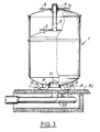
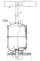
- the ovens used correspond, preferably to ovens comprising a body 1 supported by feet 6 provided with partins 7 for the grip by the fork of a forklift.
- the upper part of the body 1 is closed by a cover 8 with a sleeve 9 in which is guided a chimney 3 connected to a bell 2 movable in said body 1.
- the sleeve 9 is bordered by a circular channel 10 intended to be filled with sand and the lower part of the body 1 comprises a central duct 4 provided with a socket 5 pierced with holes 11 and making it possible to connect the oven to a sheath 12.
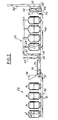
- Figure 1 shows the general layout a charcoal production installation which includes a wood storage area 20, a filling area 21 for the ovens, three charring lines 22, three corresponding drying lines 23, a cooling area 25 where the ovens are stored after carbonization and a station 26 where the ovens are emptied after cooling and where the charcoal is transported to a bagging line.
- Each carbonization line 22 comprises a concrete slab 30 on which the carbonization furnaces 1 stand on the spike, these being by lateral sheaths 12 connected to a central sheath 33 disposed below the concrete slab 30.
- the furnaces of the charring line 22 are therefore under vacuum and the combustion air is sucked through openings in the chimney 3, the wood being lit under the bell 2, the fumes, pyrolignous vapors etc. being sucked into the sheaths 12 and 33 through the openings 11 of the sleeve 5.
- the sheath 33 is connected to an incineration oven 35 which includes a burner 36, a fan 37 and a hopper 38 filled with charcoal dust.
- the fan 36 provides the air necessary for combustion in the oven 35 at the same time as it brings into the latter charcoal dust intended to promote the burning of pyroligneous vapors and to raise the temperature in the oven.
- the outlet of the incineration oven 35 is connected by a line 40 to the suction of a fan 41, the discharge of which opens into a line 42 on which branch lines 43 are connected which cover the sleeves 9 of the ovens of the drying line and whose free edge is inserted in the sand of the canals 10.
- a pipe 45 which being thus connected to the suction of the fan 41 makes it possible to suck in the ambient air to extract the stale air from the room and thus allow the renewal of the air and the ventilation of the local.
- Line 45 also makes it possible to dilute the superheated steam leaving the oven 35 and to lower the temperature thereof.
- the bell 2 In order to allow efficient drying of the wood contained in the ovens of the drying line, the bell 2 is not mounted in them, the superheated steam which is at a temperature of the order of 170 ° C. is sent by the sleeves 9 in the ovens of the drying line pass through the wood and exit through the holes 11 of the sockets 5, the latter being connected to a sheath 46 disposed under the concrete slab 30.
- the superheated steam does not exceed a temperature of around 170 ° C in order to avoid spontaneous ignition of the wood.
- the sheath 46 circulates a vapor whose temperature oscillates between 100 ° C and 150 ° C, this passing through a hydraulic filter 47 before being evacuated outside by a chimney 48.
- the hydraulic filter comprises a pump 49 which draws water into a tank 50 and discharges it into a pipe 51 terminated by a ramp 52 which sends the water in the form of droplets in the upper part of a capacity 53 connected to the cover 50 and connected on the one hand to the sheath 46 and, on the other hand, to the chimney 48.
- the hydraulic filter 47 makes it possible to wash the gases before leaving the atmosphere and to retain the particles in suspension.
- the diagram in FIG. 1 makes it possible to understand the advantage of the installation.
- the ovens are filled with wood and then with a forklift they are transported to a drying line 23. There they are connected to the branches 43.
- the bells 2 Beforehand the ovens of the drying line 23 were moved with a forklift and placed on the line carbonization 22, the bells 2 having been put in place, then, the ovens of the carbonization line 22 are ignited and the superheated vapors are used to dry the wood of the ovens of the drying line as already described above.
- the bells 2 ensure the suffocation of the ovens of the carbonization line, these then being transported from the carbonization line to the cooling area. When cooled the ovens are emptied at station 26.
Landscapes
- Chemical & Material Sciences (AREA)
- Engineering & Computer Science (AREA)
- Oil, Petroleum & Natural Gas (AREA)
- Materials Engineering (AREA)
- Organic Chemistry (AREA)
- Drying Of Solid Materials (AREA)
- Solid Fuels And Fuel-Associated Substances (AREA)
- Chemical And Physical Treatments For Wood And The Like (AREA)
- Coke Industry (AREA)
Claims (6)
Applications Claiming Priority (3)
| Application Number | Priority Date | Filing Date | Title |
|---|---|---|---|
| FR8710540A FR2618448B1 (fr) | 1987-07-24 | 1987-07-24 | Installation de production de charbon de bois |
| FR8710540 | 1987-07-24 | ||
| EP88400764A EP0335044A1 (de) | 1987-07-24 | 1988-03-29 | Einrichtung zur Herstellung von Holzkohle |
Publications (2)
| Publication Number | Publication Date |
|---|---|
| EP0300925A1 EP0300925A1 (de) | 1989-01-25 |
| EP0300925B1 true EP0300925B1 (de) | 1991-01-02 |
Family
ID=39683825
Family Applications (2)
| Application Number | Title | Priority Date | Filing Date |
|---|---|---|---|
| EP88400764A Withdrawn EP0335044A1 (de) | 1987-07-24 | 1988-03-29 | Einrichtung zur Herstellung von Holzkohle |
| EP88401934A Expired - Lifetime EP0300925B1 (de) | 1987-07-24 | 1988-07-25 | Einrichtung zur Herstellung von Holzkohle |
Family Applications Before (1)
| Application Number | Title | Priority Date | Filing Date |
|---|---|---|---|
| EP88400764A Withdrawn EP0335044A1 (de) | 1987-07-24 | 1988-03-29 | Einrichtung zur Herstellung von Holzkohle |
Country Status (4)
| Country | Link |
|---|---|
| EP (2) | EP0335044A1 (de) |
| DE (1) | DE3861361D1 (de) |
| ES (1) | ES2020337B3 (de) |
| FR (1) | FR2618448B1 (de) |
Families Citing this family (6)
| Publication number | Priority date | Publication date | Assignee | Title |
|---|---|---|---|---|
| KR0141512B1 (ko) * | 1994-06-14 | 1998-07-15 | 마재열 | 자전거의 전진구동 주행장치 |
| GB9723782D0 (en) * | 1997-11-12 | 1998-01-07 | Webster Robin | Double oven retort |
| UA49432C2 (en) * | 2001-12-07 | 2004-09-15 | Slovvazhmash Open Joint Stock | Equipment for maintenance of the battery of coke-ovens |
| RU2236435C2 (ru) * | 2002-06-20 | 2004-09-20 | Открытое акционерное общество "Сорбент" | Установка для производства топливных углей |
| RU2225877C1 (ru) * | 2003-04-09 | 2004-03-20 | Общество с ограниченной ответственностью "Сокол-лес" | Углевыжигательная печь "печюга друг" |
| CN108359508A (zh) * | 2018-03-16 | 2018-08-03 | 应佩荣 | 竹木材烘干后再装入炭窑炭化的竹木炭生产工艺 |
Family Cites Families (5)
| Publication number | Priority date | Publication date | Assignee | Title |
|---|---|---|---|---|
| FR577471A (fr) * | 1924-02-20 | 1924-09-05 | Four-cornue mobile horizontal pour carbonisation continue en vase clos du bois en forêt | |
| FR599916A (fr) * | 1925-04-24 | 1926-01-25 | Appareil portatif pour carbonisation des bois en forêt | |
| FR883470A (fr) * | 1941-06-11 | 1943-07-06 | Four de distillation du bois et des matières cellulosiques avec récupération des sous-produits et étuve de séchage | |
| US4280878A (en) * | 1979-10-30 | 1981-07-28 | Sprenger Gerald E | Structure and process for reclaiming heat from charcoal production facility |
| FR2586031A1 (fr) * | 1985-08-06 | 1987-02-13 | Sennesael Etienne | Groupe de carbonisation autosecheur et refroidisseur |
-
1987
- 1987-07-24 FR FR8710540A patent/FR2618448B1/fr not_active Expired - Fee Related
-
1988
- 1988-03-29 EP EP88400764A patent/EP0335044A1/de not_active Withdrawn
- 1988-07-25 EP EP88401934A patent/EP0300925B1/de not_active Expired - Lifetime
- 1988-07-25 ES ES88401934T patent/ES2020337B3/es not_active Expired - Lifetime
- 1988-07-25 DE DE8888401934T patent/DE3861361D1/de not_active Expired - Lifetime
Also Published As
| Publication number | Publication date |
|---|---|
| EP0300925A1 (de) | 1989-01-25 |
| ES2020337B3 (es) | 1991-08-01 |
| FR2618448A1 (fr) | 1989-01-27 |
| EP0335044A1 (de) | 1989-10-04 |
| FR2618448B1 (fr) | 1994-04-08 |
| DE3861361D1 (de) | 1991-02-07 |
Similar Documents
| Publication | Publication Date | Title |
|---|---|---|
| EP0152317B1 (de) | Heizkessel für Holz mit einer Vorheizkammer für den Brennstoff | |
| EP0055261B1 (de) | Verfahren und vorrichtung zum aufbereiten nassen materials | |
| FR2511027A1 (fr) | Installation de sechage, de pyrolyse, et le cas echeant, de gazeification, et procede pour sa mise en oeuvre | |
| EP0300925B1 (de) | Einrichtung zur Herstellung von Holzkohle | |
| EA004014B1 (ru) | Способ сборки портативной печи, способ эксплуатации портативной печи, портативная печь (варианты) | |
| JPH0747737B2 (ja) | 燻炭・木酢の製造装置および方法 | |
| EP0893651B1 (de) | Brenner für flüssigen und gasförmigen Brennstoff mit niedriger Stickoxidemission | |
| CA2101917A1 (fr) | Dispositif d'aspiration et de stockage de residus et cartouche de filtration correspondante | |
| EP0330789A1 (de) | Verfahren und Vorrichtung zum Herstellen von Holzkohle | |
| FR2583427A1 (fr) | Procede de fabrication de charbon de bois, dispositif pour sa mise en oeuvre et produits obtenus par ce procede | |
| CN108240626B (zh) | 连续式垃圾高温热裂解炉 | |
| FR2465173A1 (fr) | Procede et dispositif pour secher des produits, notamment des produits d'origine vegetale ou animale | |
| FR2995666A1 (fr) | Foyer pour combustibles ligneux | |
| CN207279651U (zh) | 一种废气焚烧装置 | |
| FR2765585A1 (fr) | Procede pour la carbonisation du bois en vase clos, et installation pour la mise en oeuvre d'un tel procede | |
| JP3057364B2 (ja) | 焼却装置 | |
| FR2561360A1 (fr) | Chaudiere de chauffage | |
| FR2761458A1 (fr) | Incinerateur de dechets liquides, pateux et solides | |
| FR2535026A1 (fr) | Chaudiere a bois ou autres materiaux combustibles solides | |
| JP3079312U (ja) | 炭焼き装置 | |
| CN107842857A (zh) | 气化燃烧垃圾焚烧炉 | |
| EP0214010A1 (de) | Brenner mit Vergasungsstufe für Heizungsvorrichtung und mit einem solchen Brenner ausgerüstete Heizungsvorrichtung | |
| JPS59145282A (ja) | 木炭の製造方法および装置 | |
| FR2505029A2 (fr) | Carbonisateur de dechets | |
| FR2514073A1 (fr) | Installation de pyrolyse, notamment pour des dechets vegetaux tels que des coques ou des enveloppes de graines, et procede de fonctionnement |
Legal Events
| Date | Code | Title | Description |
|---|---|---|---|
| PUAI | Public reference made under article 153(3) epc to a published international application that has entered the european phase |
Free format text: ORIGINAL CODE: 0009012 |
|
| AK | Designated contracting states |
Kind code of ref document: A1 Designated state(s): BE DE ES IT |
|
| 17P | Request for examination filed |
Effective date: 19890404 |
|
| 17Q | First examination report despatched |
Effective date: 19891222 |
|
| ITF | It: translation for a ep patent filed | ||
| GRAA | (expected) grant |
Free format text: ORIGINAL CODE: 0009210 |
|
| AK | Designated contracting states |
Kind code of ref document: B1 Designated state(s): BE DE ES IT |
|
| REF | Corresponds to: |
Ref document number: 3861361 Country of ref document: DE Date of ref document: 19910207 |
|
| PLBE | No opposition filed within time limit |
Free format text: ORIGINAL CODE: 0009261 |
|
| STAA | Information on the status of an ep patent application or granted ep patent |
Free format text: STATUS: NO OPPOSITION FILED WITHIN TIME LIMIT |
|
| 26N | No opposition filed | ||
| PGFP | Annual fee paid to national office [announced via postgrant information from national office to epo] |
Ref country code: BE Payment date: 19930730 Year of fee payment: 6 |
|
| PGFP | Annual fee paid to national office [announced via postgrant information from national office to epo] |
Ref country code: ES Payment date: 19930731 Year of fee payment: 6 |
|
| PGFP | Annual fee paid to national office [announced via postgrant information from national office to epo] |
Ref country code: DE Payment date: 19930806 Year of fee payment: 6 |
|
| PG25 | Lapsed in a contracting state [announced via postgrant information from national office to epo] |
Ref country code: ES Free format text: LAPSE BECAUSE OF NON-PAYMENT OF DUE FEES Effective date: 19940726 |
|
| PG25 | Lapsed in a contracting state [announced via postgrant information from national office to epo] |
Ref country code: BE Effective date: 19940731 |
|
| BERE | Be: lapsed |
Owner name: DEVALLET ANDRE Effective date: 19940731 |
|
| PG25 | Lapsed in a contracting state [announced via postgrant information from national office to epo] |
Ref country code: DE Effective date: 19950401 |
|
| REG | Reference to a national code |
Ref country code: ES Ref legal event code: FD2A Effective date: 20020603 |
|
| PG25 | Lapsed in a contracting state [announced via postgrant information from national office to epo] |
Ref country code: IT Free format text: LAPSE BECAUSE OF NON-PAYMENT OF DUE FEES;WARNING: LAPSES OF ITALIAN PATENTS WITH EFFECTIVE DATE BEFORE 2007 MAY HAVE OCCURRED AT ANY TIME BEFORE 2007. THE CORRECT EFFECTIVE DATE MAY BE DIFFERENT FROM THE ONE RECORDED. Effective date: 20050725 |