EP0300959A1 - Procédé et dispositif pour centrer un mandrin de guidage - Google Patents
Procédé et dispositif pour centrer un mandrin de guidage Download PDFInfo
- Publication number
- EP0300959A1 EP0300959A1 EP88810432A EP88810432A EP0300959A1 EP 0300959 A1 EP0300959 A1 EP 0300959A1 EP 88810432 A EP88810432 A EP 88810432A EP 88810432 A EP88810432 A EP 88810432A EP 0300959 A1 EP0300959 A1 EP 0300959A1
- Authority
- EP
- European Patent Office
- Prior art keywords
- pilot
- displacement
- clamping
- drive means
- control unit
- Prior art date
- Legal status (The legal status is an assumption and is not a legal conclusion. Google has not performed a legal analysis and makes no representation as to the accuracy of the status listed.)
- Granted
Links
- 238000000034 method Methods 0.000 title claims abstract description 29
- 238000006073 displacement reaction Methods 0.000 claims abstract description 42
- 230000004888 barrier function Effects 0.000 claims description 17
- 238000003754 machining Methods 0.000 claims description 5
- 230000000694 effects Effects 0.000 claims description 2
- 230000001960 triggered effect Effects 0.000 claims 2
- 229910000831 Steel Inorganic materials 0.000 description 8
- 239000010959 steel Substances 0.000 description 8
- 238000002485 combustion reaction Methods 0.000 description 1
- 239000000463 material Substances 0.000 description 1
- 238000005259 measurement Methods 0.000 description 1
- 238000003672 processing method Methods 0.000 description 1
Images



Classifications
-
- B—PERFORMING OPERATIONS; TRANSPORTING
- B23—MACHINE TOOLS; METAL-WORKING NOT OTHERWISE PROVIDED FOR
- B23C—MILLING
- B23C3/00—Milling particular work; Special milling operations; Machines therefor
- B23C3/02—Milling surfaces of revolution
- B23C3/05—Finishing valves or valve seats
- B23C3/051—Reconditioning of valve seats
- B23C3/053—Reconditioning of valve seats having means for guiding the tool carrying spindle
- B23C3/055—Reconditioning of valve seats having means for guiding the tool carrying spindle for engines
-
- Y—GENERAL TAGGING OF NEW TECHNOLOGICAL DEVELOPMENTS; GENERAL TAGGING OF CROSS-SECTIONAL TECHNOLOGIES SPANNING OVER SEVERAL SECTIONS OF THE IPC; TECHNICAL SUBJECTS COVERED BY FORMER USPC CROSS-REFERENCE ART COLLECTIONS [XRACs] AND DIGESTS
- Y10—TECHNICAL SUBJECTS COVERED BY FORMER USPC
- Y10S—TECHNICAL SUBJECTS COVERED BY FORMER USPC CROSS-REFERENCE ART COLLECTIONS [XRACs] AND DIGESTS
- Y10S408/00—Cutting by use of rotating axially moving tool
- Y10S408/708—Drilling opening for bearing in engine block
-
- Y—GENERAL TAGGING OF NEW TECHNOLOGICAL DEVELOPMENTS; GENERAL TAGGING OF CROSS-SECTIONAL TECHNOLOGIES SPANNING OVER SEVERAL SECTIONS OF THE IPC; TECHNICAL SUBJECTS COVERED BY FORMER USPC CROSS-REFERENCE ART COLLECTIONS [XRACs] AND DIGESTS
- Y10—TECHNICAL SUBJECTS COVERED BY FORMER USPC
- Y10T—TECHNICAL SUBJECTS COVERED BY FORMER US CLASSIFICATION
- Y10T408/00—Cutting by use of rotating axially moving tool
- Y10T408/55—Cutting by use of rotating axially moving tool with work-engaging structure other than Tool or tool-support
- Y10T408/557—Frictionally engaging sides of opening in work
- Y10T408/558—Opening coaxial with Tool
- Y10T408/5587—Valve fitting
-
- Y—GENERAL TAGGING OF NEW TECHNOLOGICAL DEVELOPMENTS; GENERAL TAGGING OF CROSS-SECTIONAL TECHNOLOGIES SPANNING OVER SEVERAL SECTIONS OF THE IPC; TECHNICAL SUBJECTS COVERED BY FORMER USPC CROSS-REFERENCE ART COLLECTIONS [XRACs] AND DIGESTS
- Y10—TECHNICAL SUBJECTS COVERED BY FORMER USPC
- Y10T—TECHNICAL SUBJECTS COVERED BY FORMER US CLASSIFICATION
- Y10T408/00—Cutting by use of rotating axially moving tool
- Y10T408/55—Cutting by use of rotating axially moving tool with work-engaging structure other than Tool or tool-support
- Y10T408/567—Adjustable, tool-guiding jig
Definitions
- valve seats When machining valve seats, especially on internal combustion engines, the highest precision of the valve seat is required.
- the valve seats are machined by turning, the shaped steel serving as turning steel being guided on a pilot, which serves as a guide mandrel in the valve guide of the valve belonging to the valve seat being machined.
- the fit of the valve achieved by this processing depends directly on the fit or the position of the pilot in the valve guide. Even if the pilot has an almost perfect fit, it is inevitable that the pilot will have some play, if only a little, in the valve guide. This is particularly the case when the valve guide is somewhat deflected and it is therefore widened in diameter towards its ends.
- the present invention relates to a method and a device by means of which such a device Pilot can be optimally centered in a valve guide, so that any pilot play in the valve guide is averaged.
- Valve seats are conventionally machined with devices which have a bearing block which is mounted on a magnetic flange.
- the magnetic flange has a flat contact surface with which it can be placed on a clamping plate and immovably fixed there by magnetic forces.
- the bearing block consists of a bearing column, on which a swivel arm is arranged adjustable in height. At its end, the swivel arm carries a holder for a swivel ball in which a pilot intended to act as a guide pin is inserted. The pilot can thus be pivoted relative to the bearing block on all sides and can be locked in any pivot position by means of the holder, which is provided with a clamping device for this purpose. A shaped steel is then mounted on the pilot as turning steel.
- the turning of the turning tool can also be done by hand with the help of mechanical, pneumatic, hydraulic or electrical drive means.
- the device is now used according to a method in which the pilot is pushed into the valve guide when the swivel ball is released. Here is a pilot as tight as possible, who should have as little play in the valve guide as possible.
- the swivel ball is clamped in its holder and then the bearing block is fixed immovably on the clamping plate by switching on the magnetic field of the magnetic flange.
- the valve seat is now gently driven down and enough material is turned off until the mold steel grazes uniformly.
- the magnet floating on an air cushion flange enables the pilot in the valve guide to take up the most stress-free position possible. Only when the magnetic flange on the clamping plate no longer moves, is it attached to the clamping plate by switching on the magnetic field. With this device, however, a certain amount of pilot play in the valve guide is inevitable, especially if the valve guide is still knocked out. Optimal centering of the pilot cannot therefore be achieved with the conventional processing devices and the methods applied with them.
- the more precise centering is intended to increase the precision of the valve seat machined by means of the shaped turning tool guided on the pilot.
- FIG. 1 shows a device for carrying out the method according to the invention. It consists of a bearing block 1 with a bearing column 3, both of which are mounted on a magnetic flange 2.
- the magnetic flange 2 is flat at the bottom and in the position of use of the device is placed on a clamping plate 22, on which it is easily displaceable when the magnet is switched off.
- the electromagnet belonging to the magnetic flange 2 is over the toggle switch 20 can be switched on and off.
- a pivot arm 4 is articulated on the bearing column 3. With the height adjustment screw 21 it can be adjusted in height on the bearing column.
- the pilot 11 is guided through the end of the swivel arm 4. It has a turning steel chuck 13 in which various shaped turning steels 12 can be used, with which the valve seats are machined.
- the cylinder head 23 with the valve seats to be machined is jammed upside down under the clamping plate 22.
- the pilot 11 which is supposed to serve as a guide mandrel for the shaped turning tool 12, is inserted here in the valve guide 25 of the valve seat 24 to be machined.
- What is now essential for the invention is the connection of the mandrel 11 to the swivel arm 4.
- the mandrel 11 is rotatably mounted in a swivel ball 7.
- this is not only pivotally mounted on all sides as in conventional devices, but also horizontally on all sides relatively displaceable relative to the swivel arm 4.
- Figure 2 shows the drive means 14 in an enlarged view in elevation.
- the swivel arm 4 which acts with its end as a clamping plate 5, lies the lower clamping shell 6.
- the swivel ball 7, in which the mandrel 11 is rotatably mounted, is inserted into it.
- the upper clamping shell 6 is placed on the swivel ball 7.
- the upper clamping plate 5, which is additionally guided on the guide supports 32, is placed on the upper clamping shell 6.
- the clamping nut 8 which is provided with an internal thread, engages, by means of which the mandrel 11 can be immovably clamped in that the swivel ball 7 can be placed under tension in its respective position between the clamping shells 6 and clamping plates 5.
- the clamping shells 6 are supplied with air for the air storage via the hoses 32.
- the lower clamping shell 6 is connected in an articulated manner to the threaded ball 18 via the pivot axis 31, which is displaceable relative to the swivel arm 4 and further via a push rod 19. This runs over the thread of the output shaft 16 of an electric motor 15.
- the end of the output shaft 16 is mounted in an output shaft bearing 26.
- the threaded ball 18 also displaces a cam 33 projecting horizontally from it.
- the displacement range of the threaded ball 18 is limited by two end light screws 27 and 28, the interruption of which triggers corresponding control signals by the cam 33.
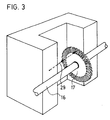
- the rotation range the output axis 16 can be measured by means of the incrementing disk 17, which continuously interrupts and releases a counting light barrier when it rotates, thereby generating counting pulses which are registered by the control unit (not shown).
- Figure 3 shows this incrementing disk 17 in an enlargement. It rotates with the output axis 16. Its edge is interrupted with slots at regular intervals. These slots pass through the light beam 29 and this is continuously interrupted and released again. Instead of a regularly slotted or toothed edge, the incrementing disk 17 can also be perforated at a constant radius distance from the axis. If the light beam is not interrupted, a photoelectric process is in progress, the continuous interruption of which generates signal pulses that can be counted by the electronic control unit.
- Figure 4 shows the drive means 14 in plan.
- the parts which are essentially visible here have already been described in detail above under FIG. 2, with the exception of the exact arrangement of the pivot axes 30, 31.
- the cams 33 on the threaded ball 18 can also be seen more clearly. If the displacement is sufficiently large on both sides, these cams 33 interrupt the light barriers 27 and 28 respectively arranged there.
- the lower clamping shell 6 can be pivoted about two different pivot axes 30 and 31.
- the pivot axis 30 is fixedly connected to the lower clamping plate 5 or the pivot arm 4.
- the swivel bracket 34 is pivotally arranged around it, which in turn is articulated at its other end to the push rod 19 and the swivel lever 35, by means of which joint the second swivel axis 31 is formed.
- the pivot lever 35 is firmly connected to the clamping shell 6.
- a second, also firmly connected to the clamping shell 6 pivot lever 36 is pivotally connected by a hinge 37 to the other push rod 19 ', but independently of the underlying pivot axis 30 already described.
- the two arrows roughly indicate the two directions of displacement, which around the two pivot axes 30 and 31 are possible.
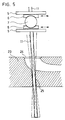
- FIG. 5 shows schematically how a pilot 11 inserted into the valve guide 25 has that game.
- this game comes from the always with egg nem error-prone fit accuracy of the pilot 11 forth, but on the other hand also from the exhaustiveness of the valve guide 25.
- the game shown here is drawn in its dimensions greatly exaggerated to show the problem underlying the invention more clearly.
- the pilot 11 can now be averaged out over two intersecting directions within the game of the pilot 11, which is deliberately not chosen too narrowly in a device according to the invention. This also averages out any error in the position of the turning plane, which the shaped turning tool to be machined describes.
- the processing method according to the invention takes place with the device described as follows: After the cylinder head 23 with the valve seats 24 to be machined is clamped in such a way that the valve seats 24 are directed upwards, the clamping plate 22 is put on and clamped with the cylinder head 23. Now the device with the magnetic flange 2 is placed on the clamping plate 22, but the pilot 11 projects down into the free space. After the magnetic flange 2 has been fastened by switching on the corresponding magnetic field by the toggle switch 20, the pilot 11 is initially roughly centered by method step a). To do this, it is released in its holder. The electronically controlled drive means 14 now move the clamping shell 6 of the holder one after the other in two intersecting directions and move the holder into the respective central positions.
- the displacement range of the holder is limited by means of a light barrier 27, 28 each.
- the drive means 14 move the clamping shell 6 about the pivot axis 30 by a forward movement to a first end position, which is achieved by moving the light barrier 27 with the cam 33.
- the displacement device is then reversed into a movement, the travel path to the other end position of the displacement area being measured. This is done with the incrementing disk 17, which rotates with the output axis 16 of the electric motor 15 and thereby continuously interrupts and releases the light barrier 29.
- the signal pulses generated thereby photoelectrically are counted by an electronic control unit until the displacement is stopped by driving over the other light barrier 28.
- the control unit now determines half the route by halving the counted signal pulses.
- the bracket is then moved to the middle po again sition of the swivel range around the axis 30
- the control takes place again by means of the incrementing disk 17, which makes the travel path countable in signal pulses until the determined number of pulses is reached, after which the electric motor 15 is stopped.
- the identical process now takes place with the opposite drive means about the pivot axis 31.
- the holder is thus finally in the middle position of its displacement range, which ensures that a determined play of the pilot 11 in the valve guide can later be averaged out in any direction.
- the holder is advantageously clamped so that forces occurring on the pilot are not transmitted to the fine drive means.
- the device is lifted off the clamping plate and the pilot 11 is inserted into the valve guide 25 of the valve seat 24 to be machined.
- the magnetic field is switched on again, as a result of which the magnetic flange 2 is fixed immovably on the clamping plate 22 for processing.
- step c the fine centering of the pilot 11 in the valve guide 25 now takes place the holder of the pilot 11 is released so that it can be moved as smoothly as possible with air bearings.
- the centering is identical to the rough centering, which was described under process step a).
- the displacement range is now not limited by light barriers, but by the respective stops of the pilot 11 in the valve guide.
- the control unit accordingly stops the shifts as soon as it registers that the incrementing disks 17, 17 'no longer rotate.
- the method for coarse and fine centering can, however, also take place in such a way that the pilot travels by correspondingly shifting the holder of the edge of his shifting area, that is to say his playing area, and this movement curve is measured, stored and calculated electronically.
- This edge can be traversed by means of drive means which are longitudinally and transversely flexibly connected to the holder.
- the movement which will be approximately circular, generally ellipsoidal, can be determined, for example, by means of two potentiometers, which are controlled by the x and y deflection, by superimposing the measuring currents. It will then the electronic control unit determines the measurement currents for the calculated center position, which can serve as characteristic values when centering with the same drive means.
- the holder of the pilot 11 is clamped firmly and immovably with the clamping means as step d). It can now serve as a guide for the shaped turning tool 12 seated on it, with which the precision machining of the valve seat 24 can now be heard.
- a pilot 11 can be centered very precisely in a valve guide. The application is reproducible and no differences in accuracy can be determined, as was previously the case. The invention enables unprecedented precise machining of valve seats.
Landscapes
- Engineering & Computer Science (AREA)
- Mechanical Engineering (AREA)
- Grinding And Polishing Of Tertiary Curved Surfaces And Surfaces With Complex Shapes (AREA)
- Drilling And Boring (AREA)
- Attitude Control For Articles On Conveyors (AREA)
- Escalators And Moving Walkways (AREA)
- Container, Conveyance, Adherence, Positioning, Of Wafer (AREA)
- Moulding By Coating Moulds (AREA)
- A Measuring Device Byusing Mechanical Method (AREA)
Priority Applications (1)
| Application Number | Priority Date | Filing Date | Title |
|---|---|---|---|
| AT88810432T ATE67698T1 (de) | 1987-07-21 | 1988-06-23 | Verfahren und vorrichtung zum zentrieren eines fuehrungsdorns. |
Applications Claiming Priority (2)
| Application Number | Priority Date | Filing Date | Title |
|---|---|---|---|
| CH2770/87 | 1987-07-21 | ||
| CH2770/87A CH674888A5 (fr) | 1987-07-21 | 1987-07-21 |
Publications (2)
| Publication Number | Publication Date |
|---|---|
| EP0300959A1 true EP0300959A1 (fr) | 1989-01-25 |
| EP0300959B1 EP0300959B1 (fr) | 1991-09-25 |
Family
ID=4241219
Family Applications (1)
| Application Number | Title | Priority Date | Filing Date |
|---|---|---|---|
| EP88810432A Expired - Lifetime EP0300959B1 (fr) | 1987-07-21 | 1988-06-23 | Procédé et dispositif pour centrer un mandrin de guidage |
Country Status (8)
| Country | Link |
|---|---|
| US (1) | US4899458A (fr) |
| EP (1) | EP0300959B1 (fr) |
| JP (1) | JPS6440207A (fr) |
| AT (1) | ATE67698T1 (fr) |
| AU (1) | AU618037B2 (fr) |
| CH (1) | CH674888A5 (fr) |
| DE (1) | DE3865137D1 (fr) |
| ES (1) | ES2027035T3 (fr) |
Cited By (7)
| Publication number | Priority date | Publication date | Assignee | Title |
|---|---|---|---|---|
| WO1997000150A1 (fr) * | 1995-06-14 | 1997-01-03 | Brice Harmand | Appareil et procede d'usinage de sieges de soupape dans une tete de cylindre de moteur |
| WO1998009759A1 (fr) * | 1996-09-09 | 1998-03-12 | Harmand Family Ltd. Partnership | Appareil et procede d'usinage de sieges de soupape dans une culasse de cylindre de moteur |
| US6086293A (en) * | 1998-04-13 | 2000-07-11 | Harmand Family Limited Partnership | Cutting tool for machining valve seats |
| US6113322A (en) * | 1998-05-29 | 2000-09-05 | Harmand Family Limited Partnership | Cylinder head clamping fixture |
| US6530727B2 (en) | 1998-04-13 | 2003-03-11 | Harmand Family Limited Partnership | Contour machining head |
| US6640410B2 (en) | 1998-04-13 | 2003-11-04 | Harmand Family Limited Partnership | Line transfer system with a contour machining head |
| CN102990163A (zh) * | 2012-11-30 | 2013-03-27 | 上海电气电站设备有限公司 | 一种发电机大电流电连接球形接头修理方法 |
Families Citing this family (17)
| Publication number | Priority date | Publication date | Assignee | Title |
|---|---|---|---|---|
| FR2648738A2 (fr) * | 1989-05-22 | 1990-12-28 | Etude Realisa Diffusion Indle | Outillage pour usinage de precision, par exemple pour la rectification de sieges de soupape |
| CH682643A5 (de) * | 1990-09-28 | 1993-10-29 | Serdi | Verfahren und Vorrichtung zum Zentrieren eines Führungsdorns in einer Ventilführung zum Zwecke des Präzisionsbearbeitens eines Ventilsitzes. |
| US5302057A (en) * | 1990-09-28 | 1994-04-12 | Serdi-Societe D'etudes De Realisation Et De Diffusion Industrielles | Method and device for centering a guide rod in a valve guide for the purpose of the precision machining of a valve seat |
| US5281057A (en) * | 1992-04-14 | 1994-01-25 | K-Line Industries, Inc. | Valve guide boring fixture |
| US5769576A (en) * | 1995-06-13 | 1998-06-23 | Machines Serdi | Device for positioning a machining spindle using its pilot rod |
| US5944458A (en) * | 1995-12-22 | 1999-08-31 | Dorris, Jr.; John W. | Boring machine alignment system and method of use |
| US6179529B1 (en) | 1997-12-24 | 2001-01-30 | Uff Machine Company | Method and apparatus for drilling a bore |
| US7220085B2 (en) * | 2003-09-17 | 2007-05-22 | Sonnax Industries, Inc. | Universal jig/work holding fixture and method of use |
| US7771144B1 (en) * | 2004-09-17 | 2010-08-10 | Sonnax Industries, Inc. | Universal jig/work holding fixture and method of use |
| US7755761B2 (en) * | 2004-11-12 | 2010-07-13 | The Boeing Company | Self-normalizing contour drilling machine |
| US20070020055A1 (en) * | 2005-07-23 | 2007-01-25 | Ore Jeremy E | Tool guide |
| CN100542752C (zh) * | 2006-01-16 | 2009-09-23 | 索奈克斯工业有限公司 | 万用固定夹具和万用铰孔装置及利用它们进行铰孔的方法 |
| TW201130465A (en) * | 2010-03-05 | 2011-09-16 | Yung-Tang Hung | Multiple-hole drilling auxiliary apparatus for dental implantation |
| US20120248079A1 (en) * | 2011-03-30 | 2012-10-04 | Marketech International Corp. | Centering structure and method for machining of a solar cell |
| CN102769063A (zh) * | 2011-05-03 | 2012-11-07 | 帆宣系统科技股份有限公司 | 用于太阳能硅芯片加工的中心定位结构及其方法 |
| US9636753B2 (en) * | 2012-02-13 | 2017-05-02 | The Commonwealth Of Australia | Alignment device for drilling or reaming an opening in a structure |
| CN117515179B (zh) * | 2024-01-05 | 2024-04-02 | 瑞星久宇燃气设备(成都)有限公司 | 一种异步杠杆结构调压器及参数获取方法 |
Citations (4)
| Publication number | Priority date | Publication date | Assignee | Title |
|---|---|---|---|---|
| AT279306B (de) * | 1967-03-01 | 1970-03-10 | Italo Minelli | Vorrichtung zum Ausdrehen von Ventilsitzen von Verbrennungskraftmaschinen |
| US3838521A (en) * | 1971-02-01 | 1974-10-01 | Tobin Arp Mfg Co | Tool setting fixture |
| US4365917A (en) * | 1979-01-08 | 1982-12-28 | Pierre Harmand | Work-holding device |
| FR2555083A1 (fr) * | 1983-11-18 | 1985-05-24 | Dassault Avions | Dispositif pour faciliter l'introduction, par un robot, d'un outil dans un trou de forme complementaire |
Family Cites Families (14)
| Publication number | Priority date | Publication date | Assignee | Title |
|---|---|---|---|---|
| US1923847A (en) * | 1930-05-31 | 1933-08-22 | Frederick W Seelert | Valve seat cutting device |
| GB613594A (en) * | 1946-06-20 | 1948-11-30 | James Edward Hawley | Improvements in or relating to valve seating and/or re-seating tools |
| US2779040A (en) * | 1954-06-03 | 1957-01-29 | Harold M Scarff | Tool-centering machine |
| US3157068A (en) * | 1962-04-02 | 1964-11-17 | Hall Toledo Inc | Apparatus for reconditioning valve guides |
| US3764204A (en) * | 1971-11-19 | 1973-10-09 | K Line Ind Inc | Valve guide boring fixture |
| US3800391A (en) * | 1972-01-06 | 1974-04-02 | R Westbrook | Apparatus for repairing valve guide openings in cylinder heads |
| DE2248180A1 (de) * | 1972-09-30 | 1974-04-04 | Volkswagenwerk Ag | Einrichtung zum aufnehmen und wiederablegen eines werkzeuges |
| US4147462A (en) * | 1977-10-25 | 1979-04-03 | Neway Manufacturing, Inc. | Machine for finishing valve seats |
| SU848973A1 (ru) * | 1979-07-09 | 1981-07-23 | За витель | Устройство дл центрировани деталейВРАщЕНи |
| SU913032A1 (ru) * | 1980-04-01 | 1982-03-15 | Viktor V Davydov | Оправка /^ля базирования детали по оси отверстия 1 |
| JPS5926411B2 (ja) * | 1981-03-07 | 1984-06-27 | 本田技研工業株式会社 | 内燃機関のバルブガイド穴とバルブシ−ト面の加工方法ならびにその装置 |
| SU1185058A1 (ru) * | 1983-07-27 | 1985-10-15 | Idelevich Adolf Ya | Оправка дл центрировани деталей по отверсти м |
| US4563824A (en) * | 1983-12-12 | 1986-01-14 | Charlton Associates | Method and apparatus for disc position centering |
| US4630977A (en) * | 1985-05-28 | 1986-12-23 | Theofanous Theos E | Valve seat resurfacing apparatus |
-
1987
- 1987-07-21 CH CH2770/87A patent/CH674888A5/de not_active IP Right Cessation
-
1988
- 1988-06-23 AT AT88810432T patent/ATE67698T1/de not_active IP Right Cessation
- 1988-06-23 EP EP88810432A patent/EP0300959B1/fr not_active Expired - Lifetime
- 1988-06-23 DE DE8888810432T patent/DE3865137D1/de not_active Expired - Fee Related
- 1988-06-23 ES ES198888810432T patent/ES2027035T3/es not_active Expired - Lifetime
- 1988-07-13 US US07/218,690 patent/US4899458A/en not_active Expired - Lifetime
- 1988-07-21 JP JP63182757A patent/JPS6440207A/ja active Pending
- 1988-11-22 AU AU25801/88A patent/AU618037B2/en not_active Ceased
Patent Citations (4)
| Publication number | Priority date | Publication date | Assignee | Title |
|---|---|---|---|---|
| AT279306B (de) * | 1967-03-01 | 1970-03-10 | Italo Minelli | Vorrichtung zum Ausdrehen von Ventilsitzen von Verbrennungskraftmaschinen |
| US3838521A (en) * | 1971-02-01 | 1974-10-01 | Tobin Arp Mfg Co | Tool setting fixture |
| US4365917A (en) * | 1979-01-08 | 1982-12-28 | Pierre Harmand | Work-holding device |
| FR2555083A1 (fr) * | 1983-11-18 | 1985-05-24 | Dassault Avions | Dispositif pour faciliter l'introduction, par un robot, d'un outil dans un trou de forme complementaire |
Cited By (11)
| Publication number | Priority date | Publication date | Assignee | Title |
|---|---|---|---|---|
| WO1997000150A1 (fr) * | 1995-06-14 | 1997-01-03 | Brice Harmand | Appareil et procede d'usinage de sieges de soupape dans une tete de cylindre de moteur |
| US5725335A (en) * | 1995-06-14 | 1998-03-10 | Harmand Family Limited Partnership | Apparatus for machining valve seats in an engine cylinder head |
| US5829928A (en) * | 1995-06-14 | 1998-11-03 | Harmand Family Limited Partnership | Apparatus and method for machining valve seats in an engine cylinder head |
| WO1998009759A1 (fr) * | 1996-09-09 | 1998-03-12 | Harmand Family Ltd. Partnership | Appareil et procede d'usinage de sieges de soupape dans une culasse de cylindre de moteur |
| US6086293A (en) * | 1998-04-13 | 2000-07-11 | Harmand Family Limited Partnership | Cutting tool for machining valve seats |
| US6382883B1 (en) | 1998-04-13 | 2002-05-07 | Harmand Family Limited Partnership | Method for lapping valve seats using a single point cutting tool |
| US6530727B2 (en) | 1998-04-13 | 2003-03-11 | Harmand Family Limited Partnership | Contour machining head |
| US6640410B2 (en) | 1998-04-13 | 2003-11-04 | Harmand Family Limited Partnership | Line transfer system with a contour machining head |
| US6113322A (en) * | 1998-05-29 | 2000-09-05 | Harmand Family Limited Partnership | Cylinder head clamping fixture |
| CN102990163A (zh) * | 2012-11-30 | 2013-03-27 | 上海电气电站设备有限公司 | 一种发电机大电流电连接球形接头修理方法 |
| CN102990163B (zh) * | 2012-11-30 | 2014-08-20 | 上海电气电站设备有限公司 | 一种发电机大电流电连接球形接头修理方法 |
Also Published As
| Publication number | Publication date |
|---|---|
| DE3865137D1 (de) | 1991-10-31 |
| JPS6440207A (en) | 1989-02-10 |
| AU2580188A (en) | 1990-05-31 |
| US4899458A (en) | 1990-02-13 |
| AU618037B2 (en) | 1991-12-12 |
| ATE67698T1 (de) | 1991-10-15 |
| ES2027035T3 (es) | 1992-05-16 |
| EP0300959B1 (fr) | 1991-09-25 |
| CH674888A5 (fr) | 1990-07-31 |
Similar Documents
| Publication | Publication Date | Title |
|---|---|---|
| EP0300959B1 (fr) | Procédé et dispositif pour centrer un mandrin de guidage | |
| DE19501178C2 (de) | Schwenkbarer Zwei-Koordinaten-Tastkopf mit horizontaler Hauptachse | |
| EP0162803A2 (fr) | Appareil de contrôle à deux flancs pour le déroulement de pignons | |
| DE19708762B4 (de) | Verfahren zum Konfigurieren einer Vorrichtung für die Positionierung von Bauteilen auf einer Maschine | |
| DE2835693C3 (fr) | ||
| DE3440356A1 (de) | Werkzeugmaschine mit automatischem wechsel der werkzeuge und der werkzeugmagazine | |
| DE19510456C2 (de) | Verfahren zur Konfigurierung einer Vorrichtung zur Befestigung von Bauteilen auf einer Maschine sowie Vorrichtung zur Durchführung dieses Verfahrens | |
| DE3016047A1 (de) | Umschaltbare biegemaschine | |
| DE3224294C2 (fr) | ||
| DE69105482T2 (de) | Verfahren und vorrichtung zum in einer punktschweisspistole oder dergleichen herstellen von elektroden. | |
| DE3784067T2 (de) | Planungsvorrichtung vom selbsttaetigen austauschtyp fuer schneidvorrichtungen. | |
| DE3828162C2 (fr) | ||
| CH663923A5 (de) | Abrichteinrichtung fuer bahngesteuertes abrichten von schleifscheibenprofilen. | |
| DE3503637A1 (de) | Werkzeugmaschine fuer die spanabhebende bearbeitung von werkstuecken mit verschiedenen werkzeugen | |
| CH682643A5 (de) | Verfahren und Vorrichtung zum Zentrieren eines Führungsdorns in einer Ventilführung zum Zwecke des Präzisionsbearbeitens eines Ventilsitzes. | |
| DE19651277A1 (de) | Universal- Fräs- und Bohrmaschine | |
| DE2541259C3 (de) | Fräseinrichtung zum Bearbeiten von Kanten von beschichteten Werkstücken | |
| EP1932603B1 (fr) | Cintreuse pour tubes pour réaliser des tubes à méandres et procédé pour la fabrication de tubes à méandres | |
| DE3426548A1 (de) | Werkzeugmaschine mit einer durch einen rechner unterstuetzten steuerung sowie werkzeugaufnahme und messeinheit fuer eine werkzeugmaschine | |
| EP0847833B1 (fr) | Magasin plat | |
| DE2220161A1 (de) | Vorrichtung zum umsetzen von teilen, insbesondere werkzeugwechselvorrichtung bei werkzeugmaschinen | |
| DE470879C (de) | Gridley-Automat | |
| DE102019122424A1 (de) | Anpassbare Werkstückhaltevorrichtung | |
| EP3557111B1 (fr) | Dispositif de positionnement permettant l'alignement de composants d'installation plus lourds | |
| CH640764A5 (en) | Method and apparatus for the electrical discharge machining of metallic workpieces |
Legal Events
| Date | Code | Title | Description |
|---|---|---|---|
| PUAI | Public reference made under article 153(3) epc to a published international application that has entered the european phase |
Free format text: ORIGINAL CODE: 0009012 |
|
| AK | Designated contracting states |
Kind code of ref document: A1 Designated state(s): AT BE CH DE ES FR GB GR IT LI LU NL SE |
|
| 17P | Request for examination filed |
Effective date: 19890710 |
|
| 17Q | First examination report despatched |
Effective date: 19901031 |
|
| GRAA | (expected) grant |
Free format text: ORIGINAL CODE: 0009210 |
|
| AK | Designated contracting states |
Kind code of ref document: B1 Designated state(s): AT BE CH DE ES FR GB GR IT LI LU NL SE |
|
| PG25 | Lapsed in a contracting state [announced via postgrant information from national office to epo] |
Ref country code: GR Free format text: LAPSE BECAUSE OF FAILURE TO SUBMIT A TRANSLATION OF THE DESCRIPTION OR TO PAY THE FEE WITHIN THE PRESCRIBED TIME-LIMIT Effective date: 19910925 |
|
| REF | Corresponds to: |
Ref document number: 67698 Country of ref document: AT Date of ref document: 19911015 Kind code of ref document: T |
|
| REF | Corresponds to: |
Ref document number: 3865137 Country of ref document: DE Date of ref document: 19911031 |
|
| ITF | It: translation for a ep patent filed | ||
| ET | Fr: translation filed | ||
| GBT | Gb: translation of ep patent filed (gb section 77(6)(a)/1977) | ||
| REG | Reference to a national code |
Ref country code: ES Ref legal event code: FG2A Ref document number: 2027035 Country of ref document: ES Kind code of ref document: T3 |
|
| PG25 | Lapsed in a contracting state [announced via postgrant information from national office to epo] |
Ref country code: LU Free format text: LAPSE BECAUSE OF NON-PAYMENT OF DUE FEES Effective date: 19920630 |
|
| PLBE | No opposition filed within time limit |
Free format text: ORIGINAL CODE: 0009261 |
|
| STAA | Information on the status of an ep patent application or granted ep patent |
Free format text: STATUS: NO OPPOSITION FILED WITHIN TIME LIMIT |
|
| 26N | No opposition filed | ||
| PGFP | Annual fee paid to national office [announced via postgrant information from national office to epo] |
Ref country code: AT Payment date: 19930524 Year of fee payment: 6 |
|
| PGFP | Annual fee paid to national office [announced via postgrant information from national office to epo] |
Ref country code: BE Payment date: 19930526 Year of fee payment: 6 |
|
| PGFP | Annual fee paid to national office [announced via postgrant information from national office to epo] |
Ref country code: NL Payment date: 19930630 Year of fee payment: 6 |
|
| PGFP | Annual fee paid to national office [announced via postgrant information from national office to epo] |
Ref country code: CH Payment date: 19940520 Year of fee payment: 7 |
|
| PGFP | Annual fee paid to national office [announced via postgrant information from national office to epo] |
Ref country code: ES Payment date: 19940622 Year of fee payment: 7 |
|
| PG25 | Lapsed in a contracting state [announced via postgrant information from national office to epo] |
Ref country code: AT Effective date: 19940623 |
|
| PG25 | Lapsed in a contracting state [announced via postgrant information from national office to epo] |
Ref country code: BE Effective date: 19940630 |
|
| BERE | Be: lapsed |
Owner name: MINELLI A.G. Effective date: 19940630 |
|
| PG25 | Lapsed in a contracting state [announced via postgrant information from national office to epo] |
Ref country code: NL Effective date: 19950101 |
|
| EAL | Se: european patent in force in sweden |
Ref document number: 88810432.0 |
|
| NLV4 | Nl: lapsed or anulled due to non-payment of the annual fee | ||
| PG25 | Lapsed in a contracting state [announced via postgrant information from national office to epo] |
Ref country code: ES Free format text: LAPSE BECAUSE OF THE APPLICANT RENOUNCES Effective date: 19950624 |
|
| PG25 | Lapsed in a contracting state [announced via postgrant information from national office to epo] |
Ref country code: LI Effective date: 19950630 Ref country code: CH Effective date: 19950630 |
|
| REG | Reference to a national code |
Ref country code: CH Ref legal event code: PL |
|
| PGFP | Annual fee paid to national office [announced via postgrant information from national office to epo] |
Ref country code: FR Payment date: 19960528 Year of fee payment: 9 |
|
| PGFP | Annual fee paid to national office [announced via postgrant information from national office to epo] |
Ref country code: SE Payment date: 19960617 Year of fee payment: 9 Ref country code: GB Payment date: 19960617 Year of fee payment: 9 |
|
| PGFP | Annual fee paid to national office [announced via postgrant information from national office to epo] |
Ref country code: DE Payment date: 19960624 Year of fee payment: 9 |
|
| PG25 | Lapsed in a contracting state [announced via postgrant information from national office to epo] |
Ref country code: GB Free format text: LAPSE BECAUSE OF NON-PAYMENT OF DUE FEES Effective date: 19970623 |
|
| PG25 | Lapsed in a contracting state [announced via postgrant information from national office to epo] |
Ref country code: SE Effective date: 19970624 |
|
| GBPC | Gb: european patent ceased through non-payment of renewal fee |
Effective date: 19970623 |
|
| PG25 | Lapsed in a contracting state [announced via postgrant information from national office to epo] |
Ref country code: FR Free format text: LAPSE BECAUSE OF NON-PAYMENT OF DUE FEES Effective date: 19980227 |
|
| EUG | Se: european patent has lapsed |
Ref document number: 88810432.0 |
|
| PG25 | Lapsed in a contracting state [announced via postgrant information from national office to epo] |
Ref country code: DE Free format text: LAPSE BECAUSE OF NON-PAYMENT OF DUE FEES Effective date: 19980303 |
|
| REG | Reference to a national code |
Ref country code: FR Ref legal event code: ST |
|
| REG | Reference to a national code |
Ref country code: FR Ref legal event code: ST |
|
| REG | Reference to a national code |
Ref country code: ES Ref legal event code: FD2A Effective date: 19991007 |
|
| PG25 | Lapsed in a contracting state [announced via postgrant information from national office to epo] |
Ref country code: IT Free format text: LAPSE BECAUSE OF NON-PAYMENT OF DUE FEES;WARNING: LAPSES OF ITALIAN PATENTS WITH EFFECTIVE DATE BEFORE 2007 MAY HAVE OCCURRED AT ANY TIME BEFORE 2007. THE CORRECT EFFECTIVE DATE MAY BE DIFFERENT FROM THE ONE RECORDED. Effective date: 20050623 |
|
| PGFP | Annual fee paid to national office [announced via postgrant information from national office to epo] |
Ref country code: IT Payment date: 20070523 Year of fee payment: 20 |
|
| PGRI | Patent reinstated in contracting state [announced from national office to epo] |
Ref country code: IT Effective date: 20091201 |